
Related Manuals for GRASS VALLEY XIP-3901


Summary of Contents for GRASS VALLEY XIP-3901
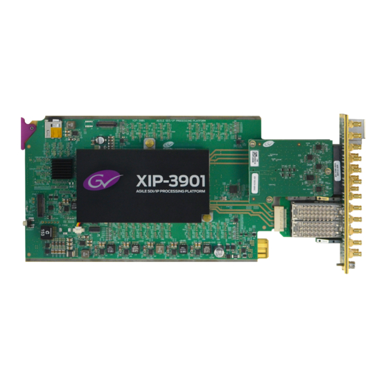
- Page 1 XIP-3901 AGILE SDI/IP PROCESSING PLATFORM User Manual 13-03065-010-AL-M00 2021-08-04...
- Page 2 Valley USA, LLC, or one of its affiliates or subsidiaries. All other intellectual property rights are owned by GVBB Holdings SARL, Grass Valley USA, LLC, or one of its affiliates or subsidiaries. All third party intellectual property rights (including logos or icons) remain the property of their respective owners.
- Page 3 Publication Date Notes 13-03065-010-AA-M00 2018-06-14 Initial release 13-03065-010-AB-M00 2018-09-25 External reference support for XIP-3901-UC 1.1 XIP-3901-DC 1.0 release Agile processing platform manager for XIP-3901-UC 1.1 and XIP-3901-DC 1.0 13-03065-010-AC-M00 2018-11-23 XIP-3901-FS 1.0 release 13-03065-010-AD-M00 2019-02-15 Improved HDR settings and options...
- Page 4 • Color Corrector (RGB Gain, Offset & Gamma) • Gamut Legalization • Detail Horizontal and Vertical enhancer support on down-converted paths. Documented the XIP-3901-UC/DC/FS V2.1.0: Support for BBC LUTs v1.4. 13-03065-010-AJ-M00 2020-09-10 Documented the XIP-3901-UDC-IP V1.2 application update. Added Support for: •...
- Page 5 Grass Valley believes this environmental information to be correct but cannot guarantee its completeness or accuracy since it is based on data received from sources outside our company. All specifications are subject to change without notice.
- Page 6 Notices Laser Safety - Fiber Output SFP and QSFP Modules Warning LASER SAFETY The average optical output power does not exceed 0 dBm (1mW) under normal operating conditions. Unused optical outputs should be covered to prevent direct exposure to the laser beam.
- Page 7 EMC Performance of Cables and Connectors Grass Valley products are designed to meet or exceed the requirements of the appropriate European EMC standards. In order to achieve this performance in real installations it is...
- Page 8 Notices All signal connections (including remote control connections) shall be made with screened cables terminated in connectors having a metal shell. The cable screen shall have a large- area contact with the metal shell. SIGNAL/DATA PORTS For unconnected signal/data ports on the unit, fit shielding covers. For example, fit EMI blanking covers to SFP+ type ports;...
-
Page 9: Table Of Contents
XIP-3901-JPEG-XS Functional Block Diagram ........... 34 3 XIP-3901 Installation and Operation ....... . 35 Front Card-edge Interface . - Page 10 Installing new applications on the XIP-3901 ........
- Page 11 Options Panel ..................112 8 Configuring the XIP-3901-UDC-IP v1.2 Application with iControl ..115 Network Panel.
- Page 12 Test Panel ..................211 10 Configuring the XIP-3901-GB-IP Application with iControl ..213 Network Panel.
- Page 13 Connecting to the XIP-3901 Card’s Configuration Interface ........
- Page 14 Replacing the XIP-3901’s Fan ........
- Page 15 XIP-3901 User Manual Installing an SFP module................295 Connecting the fiber optic cables .
- Page 16 Table of Contents...
-
Page 17: Introduction To The Xip-3901 Agile Sdi/Ip Processing Platform
Introduction to the XIP-3901 Agile SDI/IP Processing Platform The Densité 3+ XIP-3901 from Grass Valley, a Belden Brand, is a new agile processing platform that focuses on high-quality live production for HD, 1080p, 4K UHD and HDR. This platform is a bridge for the hybrid world, consisting of today’s proven SDI technology and the latest IP connectivity. - Page 18 Introduction to the XIP-3901 Agile SDI/IP Processing Platform...
-
Page 19: Applications
12G/Quad Link 3G/3G/HD HD-BNC SDI connectivity to support two 4K UHD processing paths with the XIP-3901-UC/DC/FS applications. The rear panel XIP-3901-3+DRP is also available for DIN SDI connectivity for backward compatibility, but Grass Valley is now promoting the HD-BNC as the miniature SDI connector going forward. The XIP-3901 is installed in a Densité... -
Page 20: Xip3901 -Uc / -Dc / -Fs Key Features
BT.2100) and SLog3/SGamut3 formats, with conversion between formats. In addition to the Grass Valley LUTs, you can select BBC LUTs v1.4 or you can choose your own Custom LUTs compliant to Adobe cube file v1.0 for fully flexible HDR processing. -
Page 21: Xip3901 -Uc / -Dc / -Fs Supported Video Formats
XIP-3901 User Manual XIP3901 -UC / -DC / -FS Supported Video Formats Figure 2-1: Supported Video Formats for XIP-3901 -UC / -DC / -FS Applications Note: 50/59.94 Hz frame rate conversion is not supported. Functional Block Diagrams 16ch Audio Tracking / Metadata Match Delay... -
Page 22: Xip3901-Udc-Ip Applications
Figure 2-4: XIP3901FS Functional Block Diagram XIP3901-UDC-IP Applications The XIP-3901-UDC-IP is a dual-channel 4K UHD broadcast quality format converter with optional HDR and Audio processor supporting IP with dual 25GbE I/O. Based on open standards, this IP edge processing application is compliant to SMPTE ST 2110 suite of... -
Page 23: Xip3901-Udc-Ip Key Features
These include detail enhancement, pixel-based de-interlacing, and advanced motion adaptive de-interlacing and anti-ringing. The XIP-3901-UDC-IP supports processing of common film rates 23.98p and 29.97p Hz to and from 59.94 Hz material and offers timecode selection either directly from the PTP source or the SMPTE ST 2110-40 stream for processing and regeneration. -
Page 24: Xip3901-Udc-Ip Supported Video Formats
• GV Orbit or iControl for configuration, control, and monitoring. XIP3901-UDC-IP Supported Video Formats The XIP-3901-UDC-IP supports the following ST 2110-20 Single-Stream formats. In addition the XIP-3901-UDC-IP supports processing of common film rates 23.98p and 29.97p Hz to and from 59.94 Hz material. -
Page 25: Optional Xip-3901-Udc-Ip Application Audio Processing, Down/Up Mix, Shuffling
2160 p59.94 Figure 2-5: Supported Video Formats for XIP-3901-UDC-IP Applications Optional XIP-3901-UDC-IP Application Audio processing, Down/Up Mix, Shuffling The following audio processing features are available with the XIP-3901-UDC-AUD option. • Audio probing (audio presence/ audio type) • Input mixer • Upmix •... -
Page 26: Functional Block Diagram
Figure 2-7: XIP-3901UDC-IF Operating in SDI Only Mode Figure 2-8: XIP-3901UDC-IF Operating in SDI and IP Hybrid Mode Figure 2-9: XIP-3901UDC-IF Operating in SDI and IP Hybrid Mode with IP Audio Inputs The XIP-3901-UDC-IF provides frame synchronization and video processing functions to perform up/down/crossconversion needed to maintain the chosen output format, irrespective of whether the input is HD 720p, 1080i, 1080p or UHD 2160p. -
Page 27: Xip3901-Udc-If Key Features
6 frames/fields. In a hybrid SDI-IP environment, the XIP-3901-UDC-IF dual 25 GbE I/O supports the SMPTE ST 2110 suite of standards and JT-NM TR-1001-1 technical recommendation for easy integration in a broadcast network environment. -
Page 28: Xip3901-Udc-If Supported Video Formats
• Individual XIP-3901 applications licensed, purchased as needed • Rapid switching between XIP-3901 applications • The XIP-3901-UDC-IF is also supported by the ATP-2000 Touch Panel with GV Orbit Dynamic Orchestration where all video processing parameters of both paths can be controlled from a touch panel interface XIP3901-UDC-IF Supported Video Formats... -
Page 29: Optional Xip-3901-Udc-If Application Audio Processing, Down/Up Mix, Shuffling
Figure 2-11: XIP-3901UDC-IF Functional Block Diagram XIP3901-GB-IP Application The XIP-3901-GB-IP is a dual-channel 4K UHD gearbox application for conversion between Quadstream 1080p Two Sample Interleave (2SI) or Square Division Quad Stream (SDQS) and Single-stream 4K UHD supporting IP with dual 25 GbE I/O. Based on open standards,... -
Page 30: Xip3901-Gb-Ip Key Features
2160p, which can be a gap when building a complete end-to-end 4K UHD solution. The XIP-3901-GB-IP also supports four streams of SMPTE ST 2110-30/31 audio conforming to Level A and Level C, as well as one stream of SMPTE ST 2110-40 metadata per channel of IP gearbox. -
Page 31: Xip3901-Gb-Ip Supported Video Formats
• Both FEC74 (CL74 Fire Code) and FEC108 (Reed Solomon IEEE) Forward Error Correction are supported. • GV Orbit for configuration, control and monitoring XIP3901-GB-IP Supported Video Formats The XIP-3901-GB-IP supports the following video formats conversion. XIP-3901-GB-IP Video formats supported Input Format Single Stream 2160p50 Single Stream 2160 p59.94... -
Page 32: Functional Block Diagram
Upgrade, Configuration and Control DENSITÉ 3+ FR4 STD / ADV 1GbE DENSITÉ CONTROL XIP-3901-GB-IP Dual Channel 4K UHD Gearbox IP Processing Application Figure 2-13: XIP-3901-GB-IP Functional Block Diagram Optional HDR Processing Optional HDR processing is available for the following applications only: •... -
Page 33: Xip3901-Jpeg-Xs Application
S-Log3/S-Gamut3 ↔ HLG BT.2100 S-Log3/S-Gamut3 ↔ PQ BT.2100 And ITU R BT 2111 HLG/PQ Color bar test patterns Figure 2-14: HDR/SDR Up-mapping and Down-mapping Capabilities for XIP-3901-UC / -DC / -FS & XIP-3901-UDC-IP Applications For: • XIP-3901-UC / -DC / -FS Applications, see Options Panel, on page 112. -
Page 34: Xip-3901-Jpeg-Xs Key Features
Applications XIP-3901-JPEG-XS Key Features XIP-3901-JPEG-XS Key Features • XIP-3901 application supporting ST-2110 and JT-NM TR-1001. • SDI output on the Decoder paths. • Ultra-low latency codec based on IntoPix’s ISO standardized JPEG-XS. • User selectable compression ratio from 6:1 to 36:1. (6:1 is nearly-lossless, 10:1 is visually lossless.) -
Page 35: Xip-3901 Installation And Operation
XIP-3901 Installation and Operation XIP-3901-UC, XIP-3901-DC, or XIP-3901-FS XIP-3901-UDC-IP XIP-3901-UDC-IF XIP-3901-GB-IP XIP-3901-JPEG XS Front Card-edge Interface The front card-edge of the XIP3901incorporates two elements: • Status LED (see Card-edge Status LED, on page 35) • Select button (see Local Control Using the Densité... - Page 36 XIP-3901 Installation and Operation Card-edge Status LED The LED will always show the most severe error status that has been detected and that it is configured to display. In the chart, error severity increases from left to right. Green represents no error/disabled, and flashing red represents the most severe error.
- Page 37 XIP-3901 User Manual XIP-3901 Card LED Status (default severity) -JPEG-XS Error Condition XIP-3901 2DEC/ Flashing Card LED Status -UC -DC -FS -UDC-IF -UDC-IP -GBIP 2ENC 8 DEC 8 ENC Green Yellow Red ETH1/ETH2 Link up • • • • •...
- Page 38 XIP-3901 Installation and Operation Card-edge Status LED XIP-3901 Card LED Status (default severity) -JPEG-XS Error Condition XIP-3901 2DEC/ Flashing Card LED Status -UC -DC -FS -UDC-IF -UDC-IP -GBIP 2ENC 8 DEC 8 ENC Green Yellow Red Channel 1 to 2 - Receivers...
- Page 39 XIP-3901 User Manual XIP-3901 Card LED Status (default severity) -JPEG-XS Error Condition XIP-3901 2DEC/ Flashing Card LED Status -UC -DC -FS -UDC-IF -UDC-IP -GBIP 2ENC 8 DEC 8 ENC Green Yellow Red Channel 3 to 8 - Receivers - Video 1 ST 2110-22 - Redundancy •...
- Page 40 XIP-3901 Installation and Operation Card-edge Status LED XIP-3901 Card LED Status (default severity) -JPEG-XS Error Condition XIP-3901 2DEC/ Flashing Card LED Status -UC -DC -FS -UDC-IF -UDC-IP -GBIP 2ENC 8 DEC 8 ENC Green Yellow Red Channel 3 to 8 - Receivers...
-
Page 41: Installation
Keep Fiber Connections Clean, on page 288. Getting Organized / Unpacking Make sure the following items have been shipped with your XIP-3901 order. If any of these are missing, contact your distributor or Grass Valley (see Grass Valley Technical Support, on page 308). -
Page 42: Installation Of The Rear Connector Panel And Card
Grass Valley Densité series cards are each associated with a rear connector panel, which must be installed in the Densité frame before the card can be inserted. The XIP3901 card is designed to fit into Grass Valley’s Densité3+ frames. The following rear connector panels are available: •... -
Page 43: Installation Of The Optical Interface (Option)
XIP-3901 User Manual 2 Slide the XIP3901card into the slot and push gently on the handle to seat the connectors. • When using a double-slot-width rear panel in a Densité3+FR1 frame, the card should be inserted into the lower of the two slots. -
Page 44: Rear Panel And Connectors
Fig. 3-2: XIP3901 Rear Panels Summary of Rear Panel Connections XIP39013+DR XIP39013+DRP Connector P Rear H Rear Connector Nomenclature Count Connector Type Type Used for application REF IN HD BNC XIP-3901-UC / DC / FS REF IN – External XIP-3901-UDC-IF reference, on page 45... -
Page 45: Details Of Rear Panel Connections
REF IN – External reference Connect an NTSC or PAL reference signal (SMPTE 170M/SMPTE 318M/ITU 6244 black burst).This is used with the XIP-3901-UC / DC / FS applications only. 12G/3G/HD IN – Serial digital 3G/HD Inputs Connect serial digital video signals, conforming to SMPTE ST 2081 and ST 2082 for 12G input signals, SMPTE 425M for 3G input signals or SMPTE 292M for HD input signals, to the connectors specified in the tables below. - Page 46 XIP-3901 Installation and Operation Details of Rear Panel Connections Connector Nomenclature XIP3901UC Input Signal 3G/HD IN 6 Not used 3G/HD IN 7 Not used 3G/HD IN 8 Not used Connector Nomenclature XIP3901DC Input Signal 12G/3G/HD IN 1 DC1 Quad Link 3G - Link 1/12G/3G...
-
Page 47: 12G/3G/Hd Out- Serial Digital 12G/3G/Hd Outputs
XIP-3901 User Manual 12G/3G/HD OUT– Serial digital 12G/3G/HD outputs SDI output signals appear on the rear panel connectors as shown in the table, conforming to SMPTE ST 2081 and ST 2082 for 12G output signals, SMPTE 425M for 3G output signals or SMPTE 292M for HD output signals. -
Page 48: Eth1, Eth2 - 25 Gige On Fiber (Sfp+)
In addition to video/audio/meta streams, the 25 GigE ports (media ports) support the following protocols: • PTP • NMOS IS-04 and IS-05 Note: These connections are not used for SDI applications such as XIP-3901-UC / DC / FS. To install the SFP+ cartridge, see Installing the SFP Ethernet Module, on page 295. - Page 49 Fig. 3-3: XIP-3901-UDC-IP / -GB-IP Receiver Overview • One ST 2110-20/21 Wide/Narrow profile stream supporting: • 720p, 1080i, 1080p, 2160p 50/59.94 (single-stream) for the XIP-3901-UDC-IP • Quad-stream and single-stream 2160p 50/59.94 for the XIP-3901-GB-IP • One ST 2110-40 stream associated with video •...
- Page 50 Fig. 3-5: XIP-3901-UDC-IP / -GB-IP Transmitter Overview • One ST 2110-20 Narrow profile stream supporting: • 720p, 1080i, 1080p, 2160p 50/59.94 (single-stream) for the XIP-3901-UDC-IP • Quad-stream and single-stream 2160p 50/59.94 for the XIP-3901-GB-IP • One ST 2110-40 stream associated with video •...
-
Page 51: Gige Eth3 - 1 Gige Management Port (Rj45)
• For NMOS IS-04 and IS-05 (for the XIP-3901-UDC-IP, XIP-3901-GB-IP, and XIP-3901-JPEG-XS applications only). This connection is not necessary when the XIP-3901 is used with Densité frames that are equipped with Densité 3+FR4 STD or Densité 3+ FR4 ADV frame controllers that are... -
Page 52: User Interface
See Local Control Using the XIP-3901-FS Densité Frame Control Panel, on page 57. • Grass Valley’s iControl system must be used to access the card’s XIP-3901-UDC-IP operating parameters remotely using a convenient graphical XIP-3901-UDC-IF user interface (GUI). See... -
Page 53: Connections And Cabling
Switch Typical Stream Source Fig. 4-1: Typical XIP-3901 Network Cabling when the card is installed in a Densité 3+FR1 or Densité 3+FR4 frame with a CPU-ETH3 Basic controller, then the card’s ETH3 port must be used to connect to the Management IP network. -
Page 54: Cabling To Support Smpte St 2022-7
Switch Typical Stream Source Fig. 4-2: Typical XIP-3901 Network Cabling when the XIP-3901 is used with Densité frames that are equipped with Densité 3+FR4 STD or Densité 3+ FR4 ADV frame controller that is connected to the Management IP network. - Page 55 XIP-3901 SFP2 Media Red Media Network Switch ‘Red’ Fig. 4-3: Typical SMPTE ST 2022-7 XIP-3901 Network Overview The SMPTE ST 2022-7 cabling connections are shown in greater detail below for XIP-3901. Media Network Switch ‘Red’ GigE ETH3 Multimode ETH1 Fiber...
- Page 56 Connections and Cabling Cabling to Support SMPTE ST 2022-7 Media Network Switch ‘Red’ Densité Frame ETH1 Multimode Densité Frame Ethernet Port (FRM) Fiber ETH2 Cat5 XIP-3901 Media Network Switch ‘Blue’ Management Network Switch NMOS Registry PC with RollCall...
-
Page 57: Local Control Using The Densité Frame Control Panel
Local Control Using the Densité Frame Control Panel XIP-3901-UC, XIP-3901-DC, or XIP-3901-FS XIP-3901-UDC-IP XIP-3901-UDC-IF XIP-3901-GB-IP XIP-3901-JPEG XS There are two types of local control panels: Panel type Frame models Appearance Physical Densité3+FR1 Touch-screen Densité3+FR4, GV Node To assign the local control panel to the XIP3901:... -
Page 58: Setting The Card's Ip Addresses
Front Card-edge Interface, on page 35) to assign the local control panel to operate the XIP-3901. • The STATUS LED on the XIP-3901 card edge flashes yellow. Use the control panel buttons to navigate through the menu. The menu allows you to view and set the UPC-3901 card’s current:... - Page 59 XIP-3901 User Manual level lower than the top level menu (stay within the NETWORK SETTINGS menu level or lower) when changing the network settings. A reboot takes approximately 30 seconds.
- Page 60 Local Control Using the Densité Frame Control Panel Setting the Card’s IP Addresses...
-
Page 61: Getting Started With Icontrol
Appserver. Starting iControl Solo To setup the XIP-3901 card, you must have installed on your PC iControl Solo, version 7.51 or higher. To verify the version of iControl Solo installed on your PC, go to the Help menu and select About, as shown below: iControl Solo can be downloaded from the Grass Valley website. - Page 62 Getting Started with iControl Installing new applications on the XIP-3901 1 In iControl Solo or in iControl Navigator, go in the Tools menu and select Densité Upgrade Manager, as shown below: This will start the Densité Upgrade Manager. It may take a few minutes for the frames and cards to populate the window.
- Page 63 6 Once complete, click Clear at the bottom of the Densité Upgrade Manager window. 7 Select the application you want to now use on your XIP-3901 card. Click the Available package pulldown for the corresponding XIP-3901 card you want to install/update and...
-
Page 64: Opening The Xip-3901 Panel
The installation progress bar updates, as shown below: And then it completes. The XIP-3901 card then will disappear for 30 seconds as it will reboot after the upgrade and then it will show the XIP-3901 card with the right firmware and installed package, as show below. - Page 65 XIP-3901 User Manual The iControl panel for the card then shown.
-
Page 66: Icontrol System User Interface
The XIP3901 applications can be remotely controlled using Grass Valley’s iControl system. This manual describes the control panels associated with the XIP3901 applications and their use. Please consult the iControl User’s Guide for information about setting up and operating iControl. -
Page 67: Section 1: Status Icons
XIP-3901 iControl Graphic Interface (Shown on XIP-3901-UC), on page 67. Although the example displayed is from the XIP3901UC, the XIP3901DC, XIP3901FS, XIP-3901-UDC-IP, and XIP-3901-GB-IP interfaces follow the same structure. The window title bar shows the card type and the slot number where the card is installed in its Densité... - Page 68 Figure 6-6: XIP-3901-UDC-IF Status Icons Figure 6-7: XIP-3901-GB-IP Status Icons Figure 6-8: XIP-3901 Status Message (mouse over a status icon, shown on XIP-3901-UC) The table below describes the various iControl status icons that can appear. If more than one interpretation is possible, read the error message in the iControl window to see which applies.
- Page 69 XIP-3901 User Manual Status Icon Description At least one IP status is in error. See: • Receiver Stream statuses, see: (red) • Config Tab, on page 125 • Config Tab, on page 176 • Config Tab, on page 214 • Receiver Media statuses, see: •...
- Page 70 Getting Started with iControl Section 1: Status Icons Status Icon Description Receiver Disabled. (grey) SDI IN Status (UC) SDI is present and valid. The video format is indicated when there are no errors. (green) SDI not present; or SDI invalid; or (red) SDI unsupported;...
-
Page 71: Section 2: Panel Selection Buttons
XIP-3901 User Manual Status Icon Description Network connections in progress. (yellow) Operating Mode Operating mode: Process (green) Operating mode: Color Bars & Tone (red) Health Monitoring Hardware OK. (green) Hardware failure detected. If this icon is flashing red, call Technical Support. -
Page 72: Section 3: Configuration Panel
Section 3: Configuration Panel XIP-3901-UC, XIP3901-UDC-IP XIP-UDC-IF XIP-3901-GB-IP XIP-3901-DC, and XIP-3901-FS Figure 6-9: Buttons for Each Individual Panel Section 3: Configuration Panel This main section displays the panel selected in Section 2. It may contain multiple tabs to access any appropriate sub-panel. -
Page 73: Section 4: Current Preset Or User Custom
XIP-3901 User Manual Figure 6-10: Panel Display (Shown on XIP-3901-UC) Section 4: Current Preset or User Custom The lower left corner of the window identifies the preset currently in use, “User custom” if none is applicable, or “Factory default” when the card is currently using its factory-default settings. -
Page 74: Xip-3901 Card Application Configuration
Getting Started with iControl XIP-3901 Card Application Configuration XIP-3901 Card Application Configuration Configuration Interface To Configure iControl Web Browser XIP-3901-UC, Configuring the XIP-3901-UC / -DC / -FS Applications with XIP-3901-DC, or iControl, on page 75 XIP-3901-FS XIP-3901-UDC-IP Configuring the XIP-3901-UDC-IP v1.2 Application with... -
Page 75: Configuring The Xip-3901-Uc / -Dc / -Fs Applications With Icontrol
XIP-3901-UDC-IF XIP-3901-GB-IP XIP-3901-JPEG XS This section describes the control panels associated with the XIP-3901-UC / DC / FS applications and their use. Video Input/Output Panel (XIP-3901-UC) Input/Output Config Tab This panel allows you to configure the settings for the two upconverters. Each can be... - Page 76 Configuring the XIP-3901-UC / -DC / -FS Applications with iControl Input/Output Config Tab Figure 7-1: Video I/O Config Use the pulldown menus to configure these parameters: Parameter Settings Note SDI Output Transport & Quad Link 3G – 2SI Division (default) 2160-Line Data Mapping Quad Link 3G –...
-
Page 77: Timing Tab
3Gbps legacy SMPTE 4251 SMPTE 4251 Note 3: The XIP-3901-UC supports two of the mappings of video into the serial digital interface defined by SMPTE 424M. 3G Mapping settings are ignored when the SDI Output is set to 12G. • The Level A format is the direct mapping of uncompressed 1080p (up to 60 fps) video into a serial digital interface at the nominal 3 Gbps. - Page 78 Configuring the XIP-3901-UC / -DC / -FS Applications with iControl Timing Tab Figure 7-3: Video I/O Timing The sliders can be adjusted as follows: Adjustment Range Vertical (lines) 16 to +16 Horizontal (msec) Up to 1 line: 0 to 14.82msec (59 Hz) 0 to 17.77msec (50 Hz)
- Page 79 < 4 lines < 4 lines < 4 lines The XIP-3901 has an integrated frame sync that supports synchronous and asynchronous SDI input signals. The input signals will be synchronized and realigned to either the URS or External Reference. The frame sync behaves like a frame buffer. It also supports frame skips/repeats in the case of an asynchronous SDI input.
-
Page 80: Deglitcher Tab
Configuring the XIP-3901-UC / -DC / -FS Applications with iControl Deglitcher Tab Deglitcher Tab For each processing channel, select the appropriate deglitcher mode (ON or OFF) using the pulldown menu. Figure 7-5: Deglitcher Tab When the deglitcher is enabled, the card supports a hotswitch between upstream signals without producing a freeze on the frame sync, and without producing artifacts on the output. -
Page 81: De-Interlacer Tab
XIP-3901 User Manual • Missing Reference: The External or URS reference source is missing. • Locked on Input: The reference source is set to Input. • Video Error: There is an error with the input. De-interlacer Tab Each processing channel has its own de-interlacer used during interlaced sources. The Film Mode and Video Over Film settings can either be set to On or Off. -
Page 82: Video Input/Output Panel (Xip-3901-Dc)
Configuring the XIP-3901-UC / -DC / -FS Applications with iControl Video Input/Output Panel (XIP-3901-DC) Video Input/Output Panel (XIP-3901-DC) Input/Output Config Tab This panel allows you to configure the settings for the two downconverters. Each can be configured independently. Figure 7-7: Video I/O Config... - Page 83 XIP-3901 User Manual SDI Output – SDI Output – 1920x1080p A (default) Format Resolution 1920x1080p B DL 1920x1080i 1280x720p Note 1: For each processing channel, you must select the format of the SDI input transport using the SDI Input pulldown menu. The choice will depend on the format used by the origin equipment.
-
Page 84: Timing Tab
Configuring the XIP-3901-UC / -DC / -FS Applications with iControl Timing Tab Quad Link 3G ALIGN monitors the timing of the four link inputs. The timing difference between the Quad Link 3G links shall not exceed 400 ns, as per SMPTE ST4255. - Page 85 12 ms + 2 frames 12 ms + 4 frames 67 ms 80 ms The XIP-3901 has an integrated frame sync that supports synchronous and asynchronous SDI input signals. The input signals will be synchronized and realigned to either the URS or External Reference.
-
Page 86: Deglitcher Tab
Configuring the XIP-3901-UC / -DC / -FS Applications with iControl Deglitcher Tab Signal SDI Input SDI Output Skip/Repeat Period Freeze on Input Error URS, Video 12G, 1 frame Last valid frame External 3G Level A 1 frame Last valid frame... - Page 87 The Input Timing to Reference box reports any difference in timing between the input and reference when the transition occurs. Since the XIP-3901-DC supports multiple links, the measurement displayed is taken from the first link (shown as SDI IN 1 in the Input/Output Config tab).
-
Page 88: Video Input/Output Panel (Xip-3901-Fs)
Configuring the XIP-3901-UC / -DC / -FS Applications with iControl Video Input/Output Panel (XIP-3901-FS) Video Input/Output Panel (XIP-3901-FS) Input/Output Config Tab This panel allows you to configure the settings for the two synchronizers. Each can be configured independently. Figure 7-11: Video I/O Config Use the topmost pulldown menu to select an operation mode. - Page 89 • Quad Link 3G – 2SI Division: The 4K image is sub-sampled into four full-frame images, each at half the vertical and horizontal resolution. Note 3: The XIP-3901-FS supports two of the mappings of video into the serial digital interface defined by SMPTE 424M. 3G Mapping settings are ignored when the SDI Output is set to 12G.
-
Page 90: Timing Tab
Configuring the XIP-3901-UC / -DC / -FS Applications with iControl Timing Tab Payload IDs (Transfer Characteristic, Colorimetry, and Bit depth) can be forced by selecting 3Gbps legacy in the Video Payload ID (Transfer Characteristic, Colorimetry, and Bit depth) Standards pulldown menu. Video Payload ID (Transfer Characteristic, Colorimetry, and Bit depth) Standards settings are ignored when the SDI Output is set to 3G or 12G. - Page 91 XIP-3901 User Manual Figure 7-13: Video I/O Timing The sliders can be adjusted as follows: Adjustment Range (50 Hz) Range (59 Hz) Vertical (Lines) 16 to +16 16 to +16 1920x1080p (A and B DL) Horizontal (msec) 0 to 17.771 msec 0 to 14.825 msec...
-
Page 92: 12G/3G/Hd And Quad Link 3G
Configuring the XIP-3901-UC / -DC / -FS Applications with iControl Timing Tab Operation Mode SDI Input SDI Output Frame Steps 3G Level A/B DL 1080p A 1080p A 1080p B DL 1080p B DL 1080p A 1080p B DL Quad Link 3G -... -
Page 93: 3G Level A/B Dl
XIP-3901 User Manual Processing Delay Async or Isochrone Synced & Phase- SDI Input Inputs Aligned Inputs Min. Operation (SDI output = SDI Delay Mode input) Min. Max. 59 Hz 50Hz Input < 3 lines < 3 lines < 3 lines <... -
Page 94: Quad Link 3G - 2Si/Square
Configuring the XIP-3901-UC / -DC / -FS Applications with iControl Timing Tab Processing Delay Async or Isochrone Inputs Synced & Phase-Aligned Inputs SDI Input SDI Output Min. Max. 59 Hz 50Hz URS, 3G Level A 3 ms 3 ms + 1 frame... - Page 95 XIP-3901 User Manual Processing Delay Async or Isochrone Inputs Synced & Phase-Aligned Inputs SDI Input SDI Output Min. Max. 59Hz 50Hz URS, 2SI Quad 2SI Quad Link 3G 3 ms 3 ms +1 17 ms 20 ms Link 3G Level A...
-
Page 96: Quad Link 3G To 12G
40 ms frame frames The XIP-3901 has an integrated frame sync that supports synchronous and asynchronous SDI input signals. The input signals will be synchronized and realigned to either the URS or External Reference. The frame sync behaves like a frame buffer. It also supports frame skips/repeats in the case of an asynchronous SDI input. - Page 97 XIP-3901 User Manual Min. Freeze on Delay Ref Signal SDI Input SDI Output Skip/Repeat Period Input Error Input None URS, Video HD/1080i HD/1080i 2 fields Last valid field External HD/720p HD/720p 1 frame Last valid frame 3G Level A 1 frame...
-
Page 98: Deglitcher Tab
Configuring the XIP-3901-UC / -DC / -FS Applications with iControl Deglitcher Tab Deglitcher Tab For each synchronizer, select the appropriate deglitcher mode (ON or OFF) using the pulldown menu. Figure 7-15: Deglitcher Tab When the deglitcher is enabled, the card supports a hot switch between upstream signals without producing a freeze on the frame sync, and without producing artifacts on the output. -
Page 99: Clean Switch Regions And Examples
XIP-3901 User Manual “Deglitcher Disabled”. When the deglitcher is enabled, it can display one of the following error messages in red: • Missing Reference: The External or URS reference source is missing. • Locked on Input: The reference source is set to Input. - Page 100 Configuring the XIP-3901-UC / -DC / -FS Applications with iControl Clean Switch Regions and Examples To determine the limits of a clean switch region, you must know the input’s line length in μs. The first region is delimited by +½ line and ½ line of the reference. For example, with an HD (1080i59) signal, the line length is 29.65 μs and so the first region lies between 14.83 μs...
-
Page 101: Hdr Panel
XIP-3901-UC / DC / FS applications. UC1&2 / DC1&2 / FS1&2 Tabs Grass Valley offers its own HDR processing. However, you can decide to use BBC LUTs or to load your own Custom LUTs. Furthermore, we can correct incoming Video Payload ID (Transfer Characteristic, Colorimetry, and Bit depth) without applying any HDR conversion. - Page 102 Configuring the XIP-3901-UC / -DC / -FS Applications with iControl UC1&2 / DC1&2 / FS1&2 Tabs Figure 7-19: HDR UC1 / UC2 Tab (Shown on XIP-3901-UC) Property Description Enable Set to enable color space conversion and dynamic range conversion. When disabled, incoming color space and dynamic range are bypassed without processing.
- Page 103 User Manual Property Description Grass Valley Set the LUT to use for HDR processing. The following HDR processing setting are available as part of the Grass Valley LUTs: LUTs BT.709 to BT.2020 BT.2020 to BT.709 SDR to HLG BT.2100 SDR to PQ BT.2100 HLG BT.2100 to SDR...
-
Page 104: Custom Luts Tab
SDR input. The value range must be between 100 and 1000 nits. The default Output HDR value is 203 nits. This parameter is only applied when the Grass Valley SDR to HLG BT.2100 Ref White (nits) LUT is selected. - Page 105 XIP-3901 User Manual Figure 7-20: Custom LUTs Tab Property Custom LUTs Parameters Available Values / Description Input Colorimetry BT.709, BT.2020 Input Range Narrow, Full Output Colorimetry BT.709, BT.2020 Output Range Narrow, Full Transfer Characteristic SDR, HLG, PQ, Unspecified Files –...
-
Page 106: Reference Panel
Configuring the XIP-3901-UC / -DC / -FS Applications with iControl Reference Panel Reference Panel This panel is used to select the reference to be used by the XIP-3901 to synchronize the SDI inputs. Figure 7-21: Reference Panel (Shown on XIP-3901-UC) -
Page 107: Test Panel
• UC2/DC2/FS2 on the rear panel 12G/3G/HD IN 5 connector. Note: On the XIP-3901-UC, you can enable 3G Output Minimum Delay for a 3G SDI Output in the Timing tab for a channel. On the XIP-3901-FS, you can enable Minimum Delay for a channel with the 12G/3G/HD and Quad Link 3G operation modes. - Page 108 75% white. On 3G, Quad Link 3G and 12G Video outputs, test pattern will follow the format setting. In the XIP-3901 UC only, the 75% color bar is inserted as 3G/HD SDI and upconverted to 12G/3G/Quad Link 3G.
-
Page 109: Status
The ETH3 Ethernet port is used to perform firmware upgrades and to upload HDR Custom LUTs on the XIP-3901 only if the card is installed in a Densité 3+FR1 or Densité 3+FR4 frame with a CPUETH3 Basic controller. When the card is installed in a Densité 3+FR4 frame with a CPUETH3 Standard or Advanced controller, the firmware upgrade is performed using the frame controller’s Ethernet port and HDR Custom LUTs can be uploaded through the... - Page 110 Configuring the XIP-3901-UC / -DC / -FS Applications with iControl Network Panel Figure 7-23: Network Panel (Shown on XIP-3901-UC) Property Description Hostname Set a unique network identification label by which this device will be known. Only alpha- numeric characters and the hyphen are permitted.
- Page 111 XIP-3901 User Manual Property Description Control Port The FRM port is a bridged port through the Densité frame controller. The physical frame ETH3, controller's Ethernet port must be connected to the network for this interface to work. See Cabling, on page 53. Note: The FRM port address must not contain any of...
-
Page 112: Options Panel
There is one option available for the XIP-3901-UC / -DC / -FS: • XIP-3901-UDC-HDR: Enables the card’s HDR conversion function. This option is shared by all applications; for example, when activated on a XIP-3901-UC application, it will also be activated on any XIP-3901-DC and XIP-3901-FS applications.When this option is activated, all HDR conversion settings are available. - Page 113 XIP-3901 User Manual Figure 7-25: Options Panel (Shown on XIP-3901-UC)
- Page 114 Configuring the XIP-3901-UC / -DC / -FS Applications with iControl Options Panel...
-
Page 115: Configuring The Xip-3901-Udc-Ip V1.2 Application With Icontrol
Network Panel The Network panel is used to set the network configuration of the media and control Ethernet ports on the XIP-3901-UDC-IP. ETH1 and ETH2 are media ports and ETH3 and FRM are control (management) ports. • Media ports manage PTP, video, metadata, and audio streams, as well as NMOS IS-04 and IS-05 also. - Page 116 Configuring the XIP-3901-UDC-IP v1.2 Application with iControl Interface Tab Figure 8-1: Network Interface Tab Property Description Hostname Set a unique network identification label by which this device will be known. Only alpha- numeric characters and the hyphen are permitted. Domain Name Shows the name of the domain(s) the card is part of. At least one interface must be configured with DHCP in order to be able to receive this information.
- Page 117 XIP-3901 User Manual Property Description Control Port The FRM port is a bridged port through the Densité frame controller. The physical frame ETH3 controller's Ethernet port must be connected to the network for this interface to work. See Cabling, on page 53. Note: The FRM port address must not contain any...
-
Page 118: Sfp Tab
Configuring the XIP-3901-UDC-IP v1.2 Application with iControl SFP Tab SFP Tab The SFP tab shows the media ports’ SFP cartridge status. Figure 8-2: Network SFP Tab Property Description SFP+ Module The current status of the SFP+ module. Green: SFP module detected... -
Page 119: Statistics Tab
XIP-3901 User Manual Property Description Wavelength These are values from the SFP’s Diagnostic Monitoring Interface (DMI). The background color changes according to the current state: TX Power Green: low/high warning flags RX Power Red: low/high alarm flags Temperature Grey: current state is normal... -
Page 120: Fec Tab
Configuring the XIP-3901-UDC-IP v1.2 Application with iControl FEC Tab FEC Tab This tab allows you to configure the media network’s error correction scheme for ETH 1 and ETH 2. Figure 8-4: Network FEC Tab Property Description Mode The error correction mode: •... -
Page 121: Ptp Panel
Protocol (described in IEEE Standard 1588) is used to distribute time across a packet network. It is used on both media ports (ETH1 and ETH2) for BMCA redundancy. This supports Best Master Clock Algorithm (BMCA) as per IEEE-1588-2008. The XIP-3901-UDC-IP supports: •... - Page 122 Configuring the XIP-3901-UDC-IP v1.2 Application with iControl PTP Panel Property Description Domain Specify the PTP Domain Number the card is to use to synchronize its clock. A domain is Number an interacting set of clocks that synchronize to one another using PTP. Clocks are assigned to a domain by virtue of the contents of the Subdomain name or the domain Number (IEEE 1588-2008) fields in PTP messages they receive or generate.
-
Page 123: Nmos Panel
IS-05 for connection management. Furthermore, it supports AMWA BCP-002 recommendations for Grouping NMOS Resources. XIP-3901-UDC-IP relies on an external NMOS registry that is used to register NMOS devices. You must point XIP-3901-UDC-IP to this external NMOS registry. -
Page 124: Receivers Panel
OFF: disable NMOS. This eliminates the RED status when NMOS IS-04 is not used. This is the default. Label Set the identifier by which this XIP-3901-UDC-IP card will be known in the NMOS registry, and by extension, to other NMOS devices using this NMOS registry. Registration Shows if the card has successfully registered itself in the NMOS registry. -
Page 125: Config Tab
XIP-3901 User Manual Config Tab This tab allows you to configure the expected source media’s audio channels, stream address, port, and IGMPv3 source. The receivers are SMPTE ST 2110-20 (Video1), ST 2110-40 (Meta 1), and ST 2110-30 (Audio 1, Audio 2, Audio 3, and Audio 4). - Page 126 Configuring the XIP-3901-UDC-IP v1.2 Application with iControl Config Tab Property Description Audio Type: Use the pull-down to set the audio source stream’s type for streams Audio 1 to Audio 4. • Type SMPTE ST 2110-30: for PCM linear audio (AES67 compatible) •...
-
Page 127: Timing Tab
XIP-3901 User Manual Timing Tab This tab allows you to view the network health of the stream’s connection (link latency, receiver buffer level, and offset time). Figure 8-8: Receivers Timing Tab Property Description Media Shows the stream type. The background shows the current media status:... -
Page 128: Redundancy Tab
Configuring the XIP-3901-UDC-IP v1.2 Application with iControl Redundancy Tab Property Description Buffer level Shows the amount of preloaded data stored in the receiver that is ready for use in microseconds and in percentage. The current buffer level in microseconds shows the minimum latency required to receive a continuous stream. - Page 129 XIP-3901 User Manual Figure 8-9: Receivers Redundancy Tab Property Description Media The background shows the current media status: Green: No error Red: Error Grey: Inactive Stream Shows the primary (ETH1) and secondary (ETH2) stream receiver status: Green: No error Red: Error...
-
Page 130: Senders Panel
XIP-3901-UDC-IP’s independent processing UHD channels. The Advanced tab allows you to configure the outgoing payload type and DSCP priority. The XIP-3901-UDC-IP provides an additional HD output for monitoring purposes of the first processing path’s video (UDC1) when the secondary processing path UDC2 is also configured to provide an HD Output. - Page 131 When Video in the UDC2 processing channel has also been configured to provide an HD output video stream format. Table 1 – Selecting the resolution and number of video streams to remain within the XIP-3901-UDC-IP’s output network bandwidth capacity, on page 130 for more information.
- Page 132 Configuring the XIP-3901-UDC-IP v1.2 Application with iControl UDC1 Tabs Property Description Video 1: Use the pull-down to set the video format for the destination (resolution / frame Video Format rate). Video 2 (Monitoring): Shows the video format of the secondary monitoring stream that is derived by the UDC1 processing channel and is typically used for monitoring applications.
-
Page 133: Udc2 Tab
HD Monitoring output available on the UDC1 processing channel (Video 2 (Monitoring)). See Table 1 – Selecting the resolution and number of video streams to remain within the XIP-3901-UDC-IP’s output network bandwidth capacity, on page 130 for more information. - Page 134 Configuring the XIP-3901-UDC-IP v1.2 Application with iControl UDC2 Tab Figure 8-11: Senders UDC2 Tab Property Description Video Use the pull-down to set the video format for the destination (resolution / frame rate). See Format Table 1 – Selecting the resolution and number of video streams to remain within the XIP-3901-UDC-IP’s output network bandwidth...
-
Page 135: Advanced Tab
XIP-3901 User Manual Property Description Master Set to enable a media sender. This manages both the primary and secondary streams. This can also be managed by external NMOS control. See NMOS Panel, on page 123. Media Shows the stream type. - Page 136 Configuring the XIP-3901-UDC-IP v1.2 Application with iControl Advanced Tab Figure 8-12: Senders Advanced Tab Property Description Payload Sets the RTP Payload ID value of outgoing video, metadata and audio streams. Type Possible range: 0 to 128 The default value are: •...
-
Page 137: Video Panel
User Manual Video Panel The Video panel has two tabs (UDC1 and UDC2); one for each of XIP-3901-UDC-IP’s independent processing channels. The configuration of the UDC2 tab is the same as the UDC1 tab. Only the configuration of the UDC1 tab is shown below. - Page 138 Configuring the XIP-3901-UDC-IP v1.2 Application with iControl Timing Tab Adjustment Range (50 Hz) Range (59 Hz) Description 1920x1080p (A) Horizontal (msec) 0 to 17.771 msec 0 to 14.825 msec Horizontal settings are specific to individual output formats. 1920x1080i Horizontal (msec) 0 to 35.542 msec 0 to 29.646 msec...
- Page 139 XIP-3901 User Manual Input Video Format Setting Output Video Format Line length Description Ignored 1280x720p 59Hz 22.244 μsec Frame rate follows Output - video format 1280x720p 50Hz 26.667 μsec 1920x1080p 23.98Hz 37.074 μsec 1920x1080p 29.97Hz 29.659 μsec 1920x1080i 59Hz 29.659 μsec 1920x1080i 50Hz 35.556 μsec...
-
Page 140: De-Interlacer Tab
Configuring the XIP-3901-UDC-IP v1.2 Application with iControl De-interlacer Tab De-interlacer Tab Each processing channel has its own de-interlacer for use with interlaced sources. The Film Mode and Video Over Film settings can either be set to On or Off. By default, both are set to On for optimal performance. -
Page 141: Detail Enhancer Tab
XIP-3901 User Manual Detail Enhancer Tab The Detail Enhancer allows you to apply a level of enhancement to the signal to regain lost detail or to simply create a sharper image. Horizontal and Vertical slide controllers allow you to adjust the magnitude of the enhancer to be set both horizontal and vertical directions. - Page 142 Configuring the XIP-3901-UDC-IP v1.2 Application with iControl Detail Enhancer Tab Property Description Enable Set to enable vertical and horizontal enhancement adjustment. The below settings can be adjusted, but they will only be applied when Enable is set. Mode Select the particular frequency band to be enhanced: High: Boost the high frequency content of the input signal.
-
Page 143: Video Proc Tab
XIP-3901 User Manual Video Proc Tab The Video Proc controls allow you to apply a correction to the individual signal components of the Y’CrCb color space. This follows the input colorimetry of the one selected in the HDR panel. Figure 8-16: Video Proc Tab... -
Page 144: Color Corrector Tab
Configuring the XIP-3901-UDC-IP v1.2 Application with iControl Color Corrector Tab Property Description Reset Defaults Click to revert all controls to their default settings. Color Corrector Tab The Color Corrector controls allow you to apply correction to the individual primary RGB channels. -
Page 145: Legalizer Tab
XIP-3901 User Manual Property Description Green Offset Set the Green Channel Offset value. (Lift) Blue Offset Set the Blue Channel Offset value. (Lift) Red Gamma Set the Red Gamma. Green Gamma Set the Green Gamma. Blue Gamma Set the Blue Gamma. -
Page 146: Hdr Panel
UDC1 tab. Only the configuration of the UDC1 tab is shown below. UDC1 / UDC2 Tab Grass Valley offers its own HDR processing. However, you can decide to use BBC LUTs or to load your own Custom LUTs. Furthermore, the incoming Video Payload ID (Transfer Characteristic, Colorimetry, and Bit depth) can be corrected without applying any HDR conversion. - Page 147 XIP-3901 User Manual Figure 8-19: HDR UDC1 / UDC2 Tab Property Description Enable Set to enable color space conversion and dynamic range conversion. When disabled, incoming color space and dynamic range are bypassed without processing. The Applied Conversion statuses will indicate “Bypass”. You can change the HDR processing setting values even if processing is disabled, but processing will not be performed.
- Page 148 Configuring the XIP-3901-UDC-IP v1.2 Application with iControl UDC1 / UDC2 Tab Property Description Global table > Set the LUT to use for HDR processing. The following HDR processing setting are available as part of the Grass Valley LUTs: Grass Valley LUTs •...
- Page 149 SDR input. The value range must be between 100 and 1000 nits. The default SDR to HLG value is 203 nits. This parameter is only applied when the Grass Valley SDR to HLG BT.2100 BT.2100 – LUT is selected.
-
Page 150: Custom Luts Tab
Configuring the XIP-3901-UDC-IP v1.2 Application with iControl Custom Luts Tab Property Description Applied Shows the applied conversion according to the above settings. Conversions table > Colorimetry Transfer Characteristic Range Custom Luts Tab This tab allows you to load up to 8 custom LUTs (LUT1 to LUT8) that can be selected for use in the UDC1 / UDC2 tabs. -
Page 151: Metadata Panel
Metadata Panel The Metadata panel has two tabs (UDC1 and UDC2); one for each of XIP-3901-UDC-IP’s independent processing channels. The configuration of the UDC2 tab is the same as the UDC1 tab. Only the configuration of the UDC1 tab is shown below. - Page 152 Configuring the XIP-3901-UDC-IP v1.2 Application with iControl Metadata Panel Figure 8-21: Metadata panel...
- Page 153 XIP-3901 User Manual Property Description Metadata Use any of the eight pulldowns to select the metadata you want to pass or block. You can select any predefined Metadata and the card will manage DID and SDID for you: DID (HEX) SDID (HEX) •...
-
Page 154: Audio Panel
NDF (non-drop frame). Only active when Time Code under Metadata is set to Process. Audio Panel The Audio panel has two tabs (UDC1 and UDC2); one for each of XIP-3901-UDC-IP’s independent processing channels. The configuration of the UDC2 tab is the same as the UDC1 tab. -
Page 155: Inputs Tab
There are also tabs for incoming audio: Audio 1, Audio 2, Audio 3, and Audio 4. This feature requires the XIP-3901-UDC-AUD option. See Options Panel, on page 166 for details about how to activate card options. -
Page 156: Mixer Tab
Configuring the XIP-3901-UDC-IP v1.2 Application with iControl Mixer Tab Property Description Status Shows audio group 1 to 4 detection for embedded audio: Green: Audio Group present Grey: Audio Group not present Signal is present and detected audio type is PCM... - Page 157 Audio coming from the 3rd audio receiver. Audio 4 - CH1 to CH16 Audio coming from the 4th audio receiver. This feature requires the XIP-3901-UDC-AUD option. See Options Panel, on page 166 for details about how to activate card options.
-
Page 158: Upmix Tab
Configuring the XIP-3901-UDC-IP v1.2 Application with iControl Upmix Tab Property Description Level Sets input gain level for an audio channel. At -96dB, the signal is completely muted. You can mouse over the level setting to see the available range. The range is always -96 to 12dB and can be set in 0.5 dB steps. - Page 159 XIP-3901 User Manual Figure 8-25: Audio Upmix Tab Property Description Inputs: Left (L), Select audio sources. If one or more upmix input channel is non-PCM, all UPMIX output Right (R) channels will be muted. Inputs Operation OFF: Disable upmix processing. UPMIX – CH1 to UPMIX – CH6 outputs are muted.
-
Page 160: Downmix Tab
Configuring the XIP-3901-UDC-IP v1.2 Application with iControl Downmix Tab Property Description LFE Mix Level Set the gain level for the low-frequency effects (LFE) upmix channel. Possible values are: +10.0 dB, + 9.0 dB, +7.5 dB, +6.0 dB, +4.5 dB, +3.0 dB, +1.5 dB, 0.0 dB, - 1.5 dB, -3.0 dB, -4.5 dB, -6.0 dB, and Mute. - Page 161 XIP-3901 User Manual Figure 8-26: Audio Downmix Tab Property Description Inputs: Left (L), Select audio sources. If one or more downmix input channel is non-PCM, all DMIX output Right (R), channels will be muted. Center (C), LFE, Left surround (LS) and Right...
-
Page 162: Outputs Tab
Configuring the XIP-3901-UDC-IP v1.2 Application with iControl Outputs Tab Property Description Mode LtRt: Enables the downmix of 5.1 channels into an LtRt (Left total Right total) matrix surround encoded stereo pair. LoRo: Enables the downmix of 5.1 channels into a LoRo (Left only Right only) stereo pair, which is a conventional stereo signal. - Page 163 XIP-3901 User Manual Audio Channel Description Audio 1 - CH1 to CH64 Audio coming from the 1st audio receiver. Audio 2 - CH1 to CH16 Audio coming from the 2nd audio receiver. Audio 3 - CH1 to CH16 Audio coming from the 3rd audio receiver.
-
Page 164: Test Panel
Set to mute a mixed audio channel output. By default, mixed signals are not muted. Test Panel You may activate the Color Bars & Tone test signal for the two channels independently by enabling the appropriate checkboxes. When HDR the XIP-3901-UDC-HDR option is... - Page 165 XIP-3901 User Manual activated, HDR test patterns are available. See Options Panel, on page 166 for details about how to activate card options. Figure 8-28: Test Panel Property Description Color Bars & Enables test signals at the card’s output: Tone •...
-
Page 166: Status
The following options are available for the XIP-3901-UDC-IP and XIP-3901-UDC-IF applications: • XIP-3901-UDC-HDR: Enables the card’s HDR conversion function. When this option is activated, all HDR conversion settings are available. When it is not activated, only the BT.709 to BT.2020 and BT.2020 to BT.709 settings are available. See also Optional HDR Processing, on page 32. - Page 167 XIP-3901 User Manual Once the option is activated, the status box beneath the Enter key area will show the status as active, with a green background. Figure 8-29: Typical Options Panel...
- Page 168 Configuring the XIP-3901-UDC-IP v1.2 Application with iControl Options Panel...
-
Page 169: Configuring The Xip 3901-Udc-If V3.0 Application With Icontrol
This section describes the control panels associated with the XIP-3901-UDC-IF application and its use. Setting the Card’s Operating Mode The first step to configure an XIP-3901-UCD-IF is to set the card’s Operating Mode in the Factory Presets panel. See Panel, on page 223. When the SDI Only option... - Page 170 Figure 9-1: Factory/Presets Panel Property Description Operating Mode Set the XIP-3901-UDC-IF card’s operating mode. SDI and IP Hybrid: All functions of the XIP-3901-UDC-IF application are available as shown in Figure 13 - XIP-3901-UDC-IF Functional Block Diagram, on page 27. SDI Only: Disables the IP functions of the XIP-3901-UDC-IF application. When this option is enabled: •...
-
Page 171: Network Panel
Network Panel The Network panel is used to set the network configuration of the media and control Ethernet ports on the XIP-3901-UDC-IF. The XIP-3901-UDC-IF’s Network Panel configuration is the same as the XIP-3901-UDC-IP’s Network Panel configuration, including all tabs; see Network Panel, on page 115. - Page 172 Configuring the XIP 3901-UDC-IF v3.0 Application with iControl PTP Panel Figure 9-2: PTP Panel Property Description Domain Specify the PTP Domain Number the card is to use to synchronize its clock. A domain is Number an interacting set of clocks that synchronize to one another using PTP. Clocks are assigned to a domain by virtue of the contents of the Subdomain name or the domain Number (IEEE 1588-2008) fields in PTP messages they receive or generate.
-
Page 173: Nmos Panel
This panel is available when the card’s Operating Mode in the Factory Presets panel is set to the SDI and IP Hybrid option. See Setting the Card’s Operating Mode, on page 169 for more information. The XIP-3901-UDC-IF’s NMOS Panel configuration is the same as the XIP-3901-UDC-IP’s NMOS Panel configuration; see NMOS Panel, on page 123. -
Page 174: Reference Panel
Reference Panel Reference Panel This panel is used to select the reference to be used by the XIP-3901 to synchronize the SDI inputs. Each processing channel can be locked to an independent reference source. For example, one processing channel can operate at 50Hz while the other processing channel can operate at 59.96Hz. -
Page 175: Inputs/Outputs Panel
The Inputs/Outputs panel has two tabs (UDC1 and UDC2); one for each of XIP-3901-UDC-IF’s independent processing channels. The configuration of the UDC2 tab is the same as the UDC1 tab. Only the configuration of the UDC1 tab is shown below. -
Page 176: Config Tab
Configuring the XIP 3901-UDC-IF v3.0 Application with iControl Config Tab Config Tab This panel allows you to configure the settings for one of the up / down converters. Figure 9-4: Input/Output Config Property Description Selected Input Select the card’s SDI input to use for this processing channel. See Details of Rear Panel Connections, on page 45. - Page 177 XIP-3901 User Manual Property Description Selected Set the output SDI stream’s video format. Set the SDI and SMPTE 2110-20 output video Format format. • Auto (Follow Input) • 3840x2160p 59.94 Hz / 50 Hz • 1920x1080p 59.94 Hz / 50 Hz •...
-
Page 178: Timing Tab
For each processing channel, you can adjust the timing relative to the reference. Use the slider or type a value into the data box on the right of the slider. The XIP-3901-UDC-IF’s Input/Output Panel, Timing tab configuration is the same as the XIP-3901-UDC-IP’s Receivers Panel, Timing tab configuration; see Timing Tab, on page 127. -
Page 179: Deglitcher Tab
Y’CrCb color space. This follows the input colorimetry of the one selected in the HDR panel. The XIP-3901-UDC-IF’s Input/Output Panel, Video Proc tab configuration is the same as the XIP-3901-UDC-IP’s Video Panel, Video Proc tab configuration; see Video Proc Tab, on page 143. -
Page 180: Legalizer Tab
Shuffling, on page 29 for the feature overview for this licensed option. The Receivers panel has two tabs (UDC1 and UDC2); one for each of XIP-3901-UDC-IF’s independent processing channels. The configuration of the UDC2 tab is the same as the UDC1 tab. - Page 181 XIP-3901 User Manual Figure 9-9: Receivers Config Tab Property Description Audio Type: Use the pull-down to set the audio source stream’s type for streams Audio 1 to Audio 4. • Type SMPTE ST 2110-30: for PCM linear audio (AES67 compatible) •...
-
Page 182: Timing Tab
Configuring the XIP 3901-UDC-IF v3.0 Application with iControl Timing Tab Property Description Media Shows the stream type. The background shows the current media status: Green: no error Red: error Grey: inactive RTP Stream Set to enable each stream receiver individually (primary and secondary). Stream Shows the primary (ETH1) and secondary (ETH2) stream receiver status: Green: no error... - Page 183 XIP-3901 User Manual Figure 9-10: Receivers Timing Tab Property Description Media Shows the stream type. The background shows the current media status: Green: No error Red: Error Grey: Inactive Stream Shows the primary (ETH1) and secondary (ETH2) stream receiver status:...
-
Page 184: Redundancy Tab
Configuring the XIP 3901-UDC-IF v3.0 Application with iControl Redundancy Tab Property Description Link Offset Shows the resulting link latency after being read out from receiver's buffer. This measurement is the difference between the packet RTP timestamp and the PTP time after the receiver's buffer and represents the total reception delay. -
Page 185: Senders Panel
The Senders panel has three tabs (UDC1, UDC2, and Advanced); UDC1 and UDC2 are for each of XIP-3901-UDC-IF’s independent processing UHD channels. These tabs configure the SMPTE ST 2110 outputs. The Advanced tab allows you to configure the outgoing payload type and DSCP priority. - Page 186 Configuring the XIP 3901-UDC-IF v3.0 Application with iControl UDC1 / UDC2 Tabs Figure 9-12: Senders UDC1 / UDC2 Tab Property Description Type: Use the pull-down to set the audio stream’s type for streams Audio 1 to Audio 4. Audio • Type SMPTE ST 2110-30: for PCM linear audio (AES67 compatible) •...
-
Page 187: Advanced Tab
XIP-3901 User Manual Property Description RTP Stream Set to enable a media stream sender for primary and secondary. This can also be managed by external NMOS control. See NMOS Panel, on page 123. Stream Shows the primary (ETH1) and secondary (ETH2) streaming status:... - Page 188 Configuring the XIP 3901-UDC-IF v3.0 Application with iControl Advanced Tab Figure 9-13: Senders Advanced Tab Property Description Payload Sets the RTP Payload ID value of outgoing video, metadata and audio streams. Type Possible range: 0 to 128 The default value are: •...
-
Page 189: Hdr Panel
UDC1 tab. Only the configuration of the UDC1 tab is shown below. UDC1 / UDC2 Tab Grass Valley offers its own HDR processing. However, you can decide to use BBC LUTs or to load your own Custom LUTs. Furthermore, the incoming Video Payload ID (Transfer Characteristic, Colorimetry, and Bit depth) can be corrected without applying any HDR conversion. - Page 190 Configuring the XIP 3901-UDC-IF v3.0 Application with iControl UDC1 / UDC2 Tab Figure 9-14: HDR UDC1 / UDC2 Tab...
- Page 191 • GV HLG BT.2100 to PQ BT.2100 narrow • GV S-Log3/S-Gamut3 to BT.709 800% • GV S-Log3/S-Gamut3 to PQ BT.2100 narrow • GV S-Log3/S-Gamut3 to HLG BT.2100 The configuration parameters for the Grass Valley LUTs are set in the Grass Valley LUTs table below. See below.
- Page 192 The automatic HDR processing methods are set under Auto. See below. The HDR processor will detect and identify the incoming HDR type regardless of the operation mode selected in the Global table (Grass Valley LUTs, BBC LUTs, Custom LUTs, and Auto).
- Page 193 SDR input. The value range must be between 100 and 1000 nits. The default SDR to HLG value is 203 nits. This parameter is only applied when the Grass Valley SDR to HLG BT.2100 BT.2100 – LUT is selected.
- Page 194 Configuring the XIP 3901-UDC-IF v3.0 Application with iControl UDC1 / UDC2 Tab Property Description Auto table > When the Auto parameter is set under Global, a symbol shows that the card has SDR BT.2020 detected this HDR type for the incoming video signal. narrow input Set the output HDR conversion for this input Video Payload ID (Transfer Characteristic, Colorimetry and Bit depth) type from the drop down list:...
- Page 195 XIP-3901 User Manual Property Description Auto table > When the Auto parameter is set under Global, a symbol shows that the card has PQ BT.2020 full detected this HDR type for the incoming video signal. input Set the output HDR conversion for this input Video Payload ID (Transfer Characteristic, Colorimetry and Bit depth) type from the drop down list: •...
-
Page 196: Custom Luts Tab
UDC1 / UDC2 tabs. The XIP only supports files that conform to the Adobe Cube file v1.0 format. Custom LUTs are shared among all XIP applications. This feature requires the XIP-3901-UDC-HDR option. See Options Panel, on page 166 for details about how to activate card options. -
Page 197: Metadata Panel
Metadata Panel The Metadata panel has two tabs (UDC1 and UDC2); one for each of XIP-3901-UDC-IF’s independent processing channels. The configuration of the UDC2 tab is the same as the UDC1 tab. Only the configuration of the UDC1 tab is shown below. - Page 198 Configuring the XIP 3901-UDC-IF v3.0 Application with iControl Metadata Panel Figure 9-16: Metadata panel...
- Page 199 XIP-3901 User Manual Property Description Metadata Use any of the eight pulldowns to select the metadata you want to pass or block. You can select any predefined Metadata and the card will manage DID and SDID for you: DID (HEX) SDID (HEX) •...
-
Page 200: Audio Panel
NDF (non-drop frame). Only active when Time Code under Metadata is set to Process. Audio Panel The Audio panel has two tabs (UDC1 and UDC2); one for each of XIP-3901-UDC-IF’s independent processing channels. The configuration of the UDC2 tab is the same as the UDC1 tab. -
Page 201: Inputs Tab
Down/Up Mix, Shuffling, on page 29 for the feature overview for this licensed option. Without the XIP-3901-UDC-AUD option, the following tabs are unavailable: Mixer, Upmix, and Downmix. SMPTE ST 2110-30/-31 IP audio inputs (Receiver Audio 1 / 2 / 3 / 4) are only available when the card’s Operating Mode in the Factory Presets panel is set to the SDI and IP Hybrid... - Page 202 Configuring the XIP 3901-UDC-IF v3.0 Application with iControl Inputs Tab Figure 9-18: Audio Inputs Tab...
-
Page 203: Mixer Tab
12dB and can be set in 0.5 dB steps. By default no gain level is applied (0 dB). This setting has no effect on a non-PCM audio channel except if this level is set to -96dB (signal is muted). This feature requires the XIP-3901-UDC-AUD option. See Options Panel, on page 166 for details about how to activate card options. - Page 204 Embed - CH1 to Embed - Audio coming from the – CH16 selected SDI input. This tab is available when the XIP-3901-UDC-AUD option is installed. See Options Panel, on page 166 for details about how to activate card options. Figure 9-19: Audio Mixer Tab...
-
Page 205: Upmix Tab
Audio coming from the – CH16 selected SDI input. Mixer - CH1 to CH2 Mixed audio channels. – This tab is available when the XIP-3901-UDC-AUD option is installed. See Options Panel, on page 166 for details about how to activate card options. - Page 206 Configuring the XIP 3901-UDC-IF v3.0 Application with iControl Upmix Tab Figure 9-20: Audio Upmix Tab Property Description Inputs: Left (L), Select audio sources. If one or more upmix input channel is non-PCM, all UPMIX output Right (R) channels will be muted. Inputs Operation OFF: Disable upmix processing.
-
Page 207: Downmix Tab
Mixer - CH1 to CH2 Mixed audio channels. – Upmix - CH1 to CH6 Upmixed audio channels. – This tab is available when the XIP-3901-UDC-AUD option is installed. See Options Panel, on page 166 for details about how to activate card options. - Page 208 Configuring the XIP 3901-UDC-IF v3.0 Application with iControl Downmix Tab Figure 9-21: Audio Downmix Tab Property Description Inputs: Left (L), Select audio sources. If one or more downmix input channel is non-PCM, all DMIX output Right (R), channels will be muted. Center (C), LFE, Left surround (LS) and Right...
-
Page 209: Outputs Tab
XIP-3901 User Manual Property Description Mode LtRt: Enables the downmix of 5.1 channels into an LtRt (Left total Right total) matrix surround encoded stereo pair. LoRo: Enables the downmix of 5.1 channels into a LoRo (Left only Right only) stereo pair, which is a conventional stereo signal. - Page 210 Configuring the XIP 3901-UDC-IF v3.0 Application with iControl Outputs Tab Audio Channel Description Note Audio 1 - CH1 to CH64 Audio coming from the These input streams are available when the card’s 1st audio receiver. Operating Mode in the Factory Presets panel is set to the SDI and IP Hybrid option.
-
Page 211: Test Panel
XIP-3901 User Manual Figure 9-22: Audio Outputs Tab Property Description Inputs: Mixer Select audio sources. Source A and Source B Level Sets input gain level for an audio channel. At -96dB, the signal is completely muted. You can mouse over the level setting to see the available range. The range is always -96 to 12dB and can be set in 0.5 dB steps. - Page 212 Configuring the XIP 3901-UDC-IF v3.0 Application with iControl Test Panel The XIP-3901-UDC-IF’s Test Panel configuration is the same as the XIP-3901-UDC-IP’s Test Panel configuration; see Test Panel, on page 164.
-
Page 213: Configuring The Xip-3901-Gb-Ip Application With Icontrol
Panel, on page 123. Receivers Panel The Receivers panel has two tabs (GB1 and GB2); one for each of XIP-3901-GB-IP’s independent processing channels. The configuration of the GB2 tab is the same as the GB1 tab. Only the configuration of the GB1 tab is shown below. -
Page 214: Config Tab
Configuring the XIP-3901-GB-IP Application with iControl Config Tab Each channel can: • Receive up to four SMPTE 2110-20 video streams: • 4 3G 2SI division 1080p IP input signals • 4 3G square division 1080p IP input signals •... - Page 215 XIP-3901 User Manual Figure 10-1: Receivers Config Tab Property Description Operation Quad Stream UHD 2SI Division: Provide the card with 4 3G 2SI division 1080p IP input Mode signals. Quad Stream UHD Square Division: Provide the card with 4 3G square division 1080p IP input signals.
- Page 216 Configuring the XIP-3901-GB-IP Application with iControl Config Tab Property Description Audio Type: Use the pull-down to set the audio source stream’s type for streams Audio 1 to Audio 4. • Type SMPTE ST 2110-30: for PCM linear audio (AES67 compatible) •...
-
Page 217: Timing Tab
XIP-3901 User Manual Property Description SDP File Click to show the last SDP file received through NMOS IS-05 since the last bootup. This window does not refresh automatically; you need to close and re-open the window to see an update. If the card has never received an SDP file since last its last bootup, the window will be empty. -
Page 218: Redundancy Tab
In the circumstance in which only one stream is successfully received, the resulting stream will be valid as well but without any active redundancy protection. The XIP-3901-GB-IP’s Receivers Panel, Redundancy tab configuration is the same as the XIP-3901-UDC-IP’s IP’s Receivers Panel, Redundancy tab configuration; see Redundancy Tab, on page 128. -
Page 219: Gb1 / Gb2 Tabs
XIP-3901 User Manual GB1 / GB2 Tabs These tabs allow you to configure the destination media’s video format, audio channels, and the SMPTE ST 2110 output stream’s IP addresses and port numbers. Each channel can: • Send up to four SMPTE 2110-20 video streams (Video 1 to Video 4): •... - Page 220 Configuring the XIP-3901-GB-IP Application with iControl GB1 / GB2 Tabs Property Description Quad Stream UHD 2SI Division: Sends 4 3G 2SI division 1080p IP output signals. Operation Mode Quad Stream UHD Square Division: Sends 4 3G square division 1080p IP output signals.
-
Page 221: Advanced Tab
135. Video Panel The Video panel has two tabs (GB1 and GB2); one for each of XIP-3901-GB-IP’s independent processing channels. The configuration of the GB2 tab is the same as the GB1 tab. Only the configuration of the GB1 tab is shown below. -
Page 222: Metadata Panel
17.771 μsec Metadata Panel The XIP-3901-GB-IP manages the transfer of metadata between its input and output, but does not process the metadata information regarding the video conversion. In the Metadata Panel, you can selectively pass or block any one of eight specific ANC data types by specifying the DIDs and SDIDs to be passed from input to output and those that are to be blocked. -
Page 223: Common Configuration Icontrol Panels
(unlike the restore point, which saves the settings for all applications on the platform). • User Presets. See User Presets, on page 224. • Factory. See Load Factory button, on page 225. • Profiles. See Profiles, on page 225. Figure 11-1: Factory/Presets Panel (Shown on XIP-3901-UC) -
Page 224: User Presets
Select any one of the five presets using the Card Preset Select pulldown menu. Click Load to load the contents of the selected user preset into the XIP-3901 application. All parameter settings and values will be replaced by the contents of the selected user preset. -
Page 225: Load Factory Button
Profiles Use Profiles to save or recover the entire card configuration (including user presets if desired) on an external disk, or to copy it to another XIP-3901 card located in any Densité frame in the system. Click Profiles to open the Profile Copy window. -
Page 226: Copy Profile From
Figure 11-6: Profile Copy for Card (Shown on XIP-3901-DC) Copy profile from This line shows the XIP-3901 card and its App. server, Densité frame, slot number, card type, firmware version and profile. The Profile column has a pulldown menu that allows you to select from the following... - Page 227 Note: It is a good idea to create a folder for these files, because they are not explicitly identified as XIP-3901 profiles and will be difficult to identify if not clearly named and conveniently located.
-
Page 228: Restore Profile From Disk
Restore profile from disk… Click this button to open an Open dialog box to locate and select a valid XIP-3901 profile file. • Click Open to read the contents of the file and reconfigure the XIP-3901’s profiles accordingly. -
Page 229: Alarm Config Panel
XIP-3901 User Manual Click Copy to copy the selected profiles from this card into the selected other XIP-3901 cards. • While the profile copy operation is in progress, the Transfer Status box on the right of the Copy profile to line will indicate Working against a yellow background. -
Page 230: Status/Name
Common Configuration iControl Panels Status/Name Status/Name This column contains an expandable tree listing all the alarms reported by this XIP-3901card. • Each alarm name includes an icon that shows its current status. • Some alarms may be text-only, and the alarm status is shown in the name and not by a status icon. -
Page 231: Copy To Other Cards
Click this button to open a panel that is used to copy the alarm configuration set for this card to another XIP-3901 card. • Select one or more destination cards from the list in the window by checking the boxes, or check All to select them all. -
Page 232: Get Alarm Keys
This information is entered into data boxes in the Info control panel. • Label: Enter the label that appears for the XIP-3901 application in iControl applications. • Short label: Enter the short-form label sometimes used by iControl (8 characters). - Page 233 XIP-3901 User Manual • Source ID: Enter a descriptive name for the XIP-3901 application. • Comments: Enter any desired text. The remaining data boxes show manufacturing information about the card. Figure 11-14: Info Panel (Shown on XIP-3901-UC) Three buttons in the panel give access to other information.
- Page 234 XIP-3901 application is registered. Figure 11-17: Joining Locators Window Add: Force the iControl service for this XIP-3901 application to register itself on a user- specified Jini lookup service, using the following syntax in the data box: jini://<ip_address>...
-
Page 235: Application Panel
To activate an application: 1 Call Grass Valley at the number displayed at the bottom of the panel and provide your serial number to receive a license key. 2 In the License column for the application, click Activate. - Page 236 Common Configuration iControl Panels Application Panel Once an application has been activated, it cannot be deactivated. To switch to a different application: 1 Select the In Use radio button for the application you wish to use. 2 In the Change application dialog box, click Apply. 3 Wait several seconds for the application to reboot.
-
Page 237: Getting Started With The Card's Web-Based Configuration Interface
Here are the ways to connect to the card’s Web-based configuration interface: • Through GV Orbit. GV Orbit will discover and show the XIP-3901-JPEG-XS as any other application. The web page can be viewed through GV Orbit. You do not need to know the address of the card’s control port. -
Page 238: Card Upgrade When The Xip-3901-Jpeg-Xs Application Is Currently Running On The Card
Card, on page 238 • You have an XIP-3901 card, but the XIP-3901-JPEG-XS application is not installed. In this case, you will have to install the XIP-3901-JPEG-XS application through the Densité Update Manager (DUM) using a DUM package. This adds the XIP-3901-JPEG-XS application to the card. - Page 239 XIP-3901 User Manual 3 Click Click to choose an application package or drop it here. A File Upload window opens. 4 Find the upgrade package file on your PC and click Open. The file is uploaded to the card. A progress bar shows the current upload status.
-
Page 240: Card Upgrade When Another Application Is Currently Running On The Card
XIP-3901-JPEG-XS application and then upgrade the card’s firmware. Proceed as follows. 1 If the XIP-3901-JPEG-XS application has never been installed on the card, you need to Install the XIP-3901-JPEG-XS application through the Densité Update Manager (DUM) using a DUM package. See Card Upgrade with iControl Solo, on page 61. - Page 241 XIP-3901 User Manual 4 Ensure the XIP-3901-JPEG-XS application is licensed. See Activating an Application, on page 274. 5 Update the card’s application through the card’s web page. See Card Upgrade when the XIP-3901-JPEG-XS Application is Currently Running on the Card, on page 238. This is...
-
Page 242: Card's Web-Based User Interface Overview
Densité frame. Application name [Friendly name/ Densité frame slot Section 1: Status Section 2: number] Operating mode Dashboard Bandwidth Usage Section 3: Panel Section 4: Card’s Current Selection Tree Configuration Software Panel Version Figure 12-1: Typical XIP-3901 Web Interface... -
Page 243: Section 1: Status Dashboard
Mousing over an icon will display a status message with additional information. Figure 12-3: Typical XIP-3901 Status Message (mouse over a status icon) The table below describes the various status icons that can appear. If there is an error, a status message is shown in a popup. -
Page 244: Section 2: Bandwidth Usage
You must ensure that your configuration never allows the card’s input or output bandwidth to be oversubscribed. When the XIP-3901’s maximum input or output bandwidth is oversubscribed (total streams require more than the available bandwidth of the SFP cartridge or network capacity), the symptoms are that of packet loss: missing blocks of video, audio dropout, and random loss of ancillary data on both processing channels. -
Page 245: Section 3: Panel Selection Tree
Click a button in the left portion of the window to select a configuration panel. The button is highlighted when it is selected. Click in the tree to open the tree structure. Figure 12-5: Configuration Panel Selection Tree See also XIP-3901-JPEG-XS Panel Selection Tree, on page 251. -
Page 246: Section 4: Configuration Panel
This main section displays the panel selected in Section 2. It may contain multiple tabs to access any appropriate sub-panel. Figure 12-6: Typical Panel Display (Shown on XIP-3901-JPEG-XS) Using the Channel Selector The channel selector allows you to select one of the card’s independent processing channels to be configured. -
Page 247: Card Status Messages
To clear all messages at once, click on your browser’s refresh button. XIP-3901 Card Application Configuration Configuration Interface To Configure iControl Web Browser XIP-3901-UC, Configuring the XIP-3901-UC / -DC / -FS Applications with XIP-3901-DC, or iControl, on page 75 XIP-3901-FS XIP-3901-UDC-IP Configuring the XIP-3901-UDC-IP v1.2 Application with... - Page 248 Getting Started with the Card’s Web-based Configuration Interface XIP-3901 Card Application Configuration Configuration Interface To Configure iControl Web Browser XIP-3901-GB-IP Configuring the XIP-3901-GB-IP Application with iControl, on page 213 XIP-3901-JPEG-XS Configuring the XIP 3901-JPEG-XS v1.0 Application with its ...
-
Page 249: Configuring The Xip 3901-Jpeg-Xs V1.0 Application With Its Web Interface249
This section describes the control panels associated with the XIP-3901-JPEG-XS application and its use. Setting the Card’s Operation Mode The first step to configure an XIP-3901-JPEG-XS is to set the card’s Operation Mode. Figure 13-1: Factory/Presets Panel Property Description Operating Mode Set the XIP-3901-JPEG-XS card’s operating mode. -
Page 250: Processing Channel Selection And Video In And Video Out
The XIP-3901-JPEG-XS has either four or eight Channel tabs, depending on the card’s Operation Mode setting. Select a channel to configure it. Property Description Click a Channel tab to access the configuration of any one of the XIP-3901-JPEG-XS’s independent processing channels. This may display as a •... -
Page 251: Xip-3901-Jpeg-Xs Panel Selection Tree
Click an entry in the panel selection tree to view the configuration panel. For more information about the panel selection tree, see also Section 3: Panel Selection Tree, on page 245. Figure 13-2: XIP-3901-JPEG-XS Panel Selection Tree For more information about the configuration panels, see: • Receivers Panel, on page 252 •... -
Page 252: Receivers Panel
Configuring the XIP 3901-JPEG-XS v1.0 Application with its Web Interface Receivers Panel Receivers Panel These signals are available at the rear panel connectors. See Summary of Rear Panel Connections, on page 44. For a JPEG-XS Encoder Channel: This panel allows you to configure the expected source media’s stream address, port, and IGMPv3 source. - Page 253 XIP-3901 User Manual For a JPEG-XS Decoder Channel: This panel allows you to configure the expected source media’s video, metadata, and audio channels, stream address, port, and IGMPv3 source. The receivers are SMPTE ST 2110-22 (Video 1), ST 2110-40 (Meta 1), and ST 2110-30/31 (Audio 1).
- Page 254 Configuring the XIP 3901-JPEG-XS v1.0 Application with its Web Interface Receivers Panel Property ENC DEC Description • Audio 1 When this channel is decoding a JPEG-XS video stream only: ST 2110-30/31 Type: Use the pull-down to set the audio stream’s type for streams Audio 1. •...
- Page 255 XIP-3901 User Manual Property ENC DEC Description • • Master Set to enable a media receiver. This manages the Join/Release of both the primary and secondary streams. You must click Apply or press <Enter> to activate the change you have made to this setting.
- Page 256 Configuring the XIP 3901-JPEG-XS v1.0 Application with its Web Interface Receivers Panel Property ENC DEC Description • • Link Latency Shows the time it takes for a packet to come from the source to the receiver. This measurement represents the difference between incoming RTP timestamp and PTP time before the receiver's buffer.
-
Page 257: Senders Panel
XIP-3901 User Manual Senders Panel For a JPEG-XS Encoder Channel: This panel allows you to configure the destination media’s JPEG-XS compression level, and the SMPTE ST 2110-22 output stream’s IP addresses and port numbers for the processing channel (Video 1). Statuses confirm that the RTP stream is successfully streaming. - Page 258 Bandwidth (Mbps): Shows JPEG-XS video stream output bandwidth to be used with the selected compression ratio and current video format settings. Extension segment: Set to ON to insert an extension segment into the JPEG- XS stream with the following string: GRASS VALLEY Copyright-Powered by IntoPIX. •...
-
Page 259: Video Panel
XIP-3901 User Manual Property ENC DEC Description • • TX Stream Set the IP address and UDP port number of the outgoing stream. IP address Address 0.0.0.0 disables a sender. The default UDP port values are 10000. Address & UDP port can also be managed by external NMOS control. See •... - Page 260 Configuring the XIP 3901-JPEG-XS v1.0 Application with its Web Interface Video Panel Format 1080p59 1080i59 720p59 2160p50 1080p50 1080i50 720p50 For a JPEG-XS Encoder Channel: For the encoder, the processing delay is always at minimum delay. The output is not timestamped as a new source.
- Page 261 XIP-3901 User Manual Property ENC DEC Description • Processing Set to minimize processing delay. Video output will not be aligned to PTP. Processing delay will still be affected by setting of the Tolerance parameter. Delay - Minimum See the Tolerance parameter in Receivers Panel, on page 252.
-
Page 262: Audio Panel
Configuring the XIP 3901-JPEG-XS v1.0 Application with its Web Interface Audio Panel Property ENC DEC Description • Colorimetry Shows colorimetry information from the SDP file and allows the colorimetry to be overwritten. Input / Detected: Shows the detected Transfer Characteristic, Colorimetry, and Bit depth (Range) information contained within the SDP file (from an NMOS join). -
Page 263: Test Panel
XIP-3901 User Manual Property ENC DEC Description • Presence & Shows Audio 1 detection for embedded audio: Audio Type Signal is present and detected audio type is PCM Signal is present and detected audio type is NPCM Signal is present and detected audio type is Dolby E... -
Page 264: Status
Configuring the XIP 3901-JPEG-XS v1.0 Application with its Web Interface Status Property Description Type Set video test pattern format for 1080p & 2160p Video outputs: • SDR BT.709 (75%): 75% Color bar with 75% white • HLG BT.2110-0: Test pattern HLG narrow range as per ITU-R BT.2111-0 •... -
Page 265: Interfaces Panel
XIP-3901 User Manual Property Description Payload Sets the RTP Payload ID value of outgoing video, metadata and audio streams. Type Possible range: 0 to 128 The default value are: • 97 for SMPTE 2110-20 (Video) • 112 for SMPTE 2110-22 (Video) •... - Page 266 Configuring the XIP 3901-JPEG-XS v1.0 Application with its Web Interface Interfaces Panel Property Description Hostname Set a unique network identification label by which this device will be known. Only alpha- numeric characters and the hyphen are permitted. Domain Name Shows the name of the domain(s) the card is part of. At least one interface must be configured with DHCP in order to be able to receive this information.
-
Page 267: Fec Panel
XIP-3901 User Manual Property Description Apply When active, this applies or rejects your current changes made in this tab. Pending changes are displayed in red. Pressing <Enter> also applies your changes. Cancel FEC Panel The FEC panel allows you to configure the media network’s error correction scheme for ETH 1 and ETH 2. -
Page 268: Sfp Panel
Configuring the XIP 3901-JPEG-XS v1.0 Application with its Web Interface SFP Panel SFP Panel The SFP panel shows the media ports’ SFP cartridge status. Figure 13-13: SFP Panel Property Description SFP+ Module The current status of the SFP+ module. Green: SFP module detected Grey: SFP mode not detected Type The connection media type. -
Page 269: Statistics Panel
PTP Panel Multicast Precision Timing Protocol (described in IEEE Standard 1588) is used to distribute time across a packet network. The XIP-3901-JPEG-XS uses PTP as a system clock and for output alignment using a frame buffer. It is used on both media ports (ETH1 and ETH2) for BMCA redundancy. This supports Best Master Clock Algorithm (BMCA) as per IEEE-1588-2008. - Page 270 Configuring the XIP 3901-JPEG-XS v1.0 Application with its Web Interface PTP Panel Property Description Domain Specify the PTP Domain Number the card is to use to synchronize its clock. A domain is Number an interacting set of clocks that synchronize to one another using PTP. Clocks are assigned to a domain by virtue of the contents of the Subdomain name or the domain Number (IEEE 1588-2008) fields in PTP messages they receive or generate.
-
Page 271: Nmos Panel
OFF: disable NMOS. This eliminates the RED status when NMOS IS-04 is not used. This is the default. Label Set the identifier by which this XIP-3901-JPEG-XS card will be known in the NMOS registry, and by extension, to other NMOS devices using this NMOS registry. Registration Shows if the card has successfully registered itself in the NMOS registry. - Page 272 Configuring the XIP 3901-JPEG-XS v1.0 Application with its Web Interface NMOS Panel Property Description Registry IS-04, Set the IS-04, Registry Mode: Registry Mode Auto: automatic discovery of the NMOS registry using DNS Service Discovery (DNS-SD), as described in AMWA IS-04 NMOS Discovery and Registration Specification v1.2. Static: manually specified NMOS registry values for address, registration port and query port.
-
Page 273: Info Panel
XIP-3901 User Manual Info Panel When this card is used in a control system such as GV Orbit, certain information about the card can be made available to control system. You can enter labels and comments that will make this card easy to identify in a complex setup. This information is entered into data boxes in the Friendly Names part of the panel. -
Page 274: Operation Mode
Activating an Application 1 Call Grass Valley at the number displayed at the bottom of the panel and provide your serial number to receive a license key. 2 In the License column for the application, enter the license key and click Activate. -
Page 275: Switching To A Different Application
XIP-3901 User Manual Switching to a Different Application 1 Select the In Use radio button for the application you want to change to. Figure 13-20: Applications Panel 2 In the Confirmation dialog box, click OK. Figure 13-21: Confirmation 3 Wait several seconds for the application to reboot. -
Page 276: Alarm Configuration Panel
Configuring the XIP 3901-JPEG-XS v1.0 Application with its Web Interface Alarm Configuration Panel Alarm Configuration Panel This panel is used to configure the alarm reporting of the XIP-3901 application. It has an expandable tree listing all the alarms reported by this XIP-3901card. Figure 13-22: Alarm Configuration Panel... - Page 277 XIP-3901 User Manual Property Description Apart from the Global alarms, click a Contribution column item to set the severity level of Contribution each individual alarm to the alarm named in the column heading. This applies to the front card -edge LED and to the alarms reported to GV Orbit. See...
-
Page 278: Factory/Presets Panel
Name: Set a name or rename a preset by typing a new name in the preset Name field. (up to 16 characters) User Setting: Click Load to load the contents of the user preset into the XIP-3901 application. All parameter settings and values will be replaced by the contents of the selected user preset. -
Page 279: Upgrade Panel
Technical Support Panel Property Description Contact If you have any questions or suggestions, contact Grass Valley Technical Support. Reboot Card Click to reboot the card System A system snapshot creates a compressed file that contains information that can be used Snapshot by Grass Valley Technical Support for troubleshooting purposes. - Page 280 Configuring the XIP 3901-JPEG-XS v1.0 Application with its Web Interface Technical Support Panel...
-
Page 281: Maintenance & Troubleshooting
IMPORTANT The rear panel must be installed before a XIP-3901 is inserted into the frame. The XIP-3901 must be removed from the frame before the rear panel can be removed. -
Page 282: Replacing A Rear Panel
Schedule these maintenance operations during off hours when the system is not in use. Diagnostics The XIP-3901’s electronic circuitry generates heat that must be shed by forcing air to move across heat-generating components. Reduced air flow or high ambient temperature results in heat build-up within temperature-sensitive components within the XIP-3901. -
Page 283: Critical Temperature Alarm Corrective Actions
To confirm that the XIP-3901 has an abnormally-sounding fan, during off hours when the system is not in use, eject the XIP-3901 card from the frame to verify that the distinctive sound stops and take corrective actions (see below). -
Page 284: Replacing The Xip-3901'S Fan
• Compressed air to remove dust from the XIP-3901. • Needle-nose pliers to separate push pins from the PCB. • Curved tweezers to disconnect the fan’s power connector from the XIP-3901’s main board. • Anti-static bag or anti-static work surface to reduce the possibility of electrostatic discharge damage to the XIP-3901’s electronics. -
Page 285: Procedure
Procedure Step 1: Remove the failed fan assembly 1 During off hours when the system is not in use, eject the XIP-3901 card from the Densité frame. 2 Flip the card over on an anti-static mat so that you can see the rear (solder side) of the card. - Page 286 Maintenance & Troubleshooting Procedure Fig. 14-3: Prying Out the Pushpins 5 Remove the wires from both wire clips on the fan assembly. 6 Note the position of the black wire to assist with reconnecting the replacement assembly. 7 Use tweezers to gently disconnect the power connector on the fan assembly from the card.
-
Page 287: Troubleshooting
Card Upgrade XIP-3901-JPEG-XS , on page 237 2 The Status Indicators on the XIP-3901 show if it is powered and these indicators provide troubleshooting information. See , on page 35. Front Card-edge Interface 3 Make sure the fiber connectors are clean, as the problem is often related to dust obstructing the light at the fiber connections. -
Page 288: Keep Fiber Connections Clean
For best results, it should be possible for you to perform a visual inspection of the fiber ends to verify cleanliness. Grass Valley strongly urges you to select a cleaning method that meets your needs, and to use it rigorously and consistently. - Page 289 XIP-3901 MV SDC Chapter User Manual • Insert a dust plug into the empty SFP module’s optical port. • Install caps on the open end of the fiber optic cable. This keeps airborne particles from settling on the fiber end or in the SFP module’s optical port.
- Page 290 Maintenance & Troubleshooting Keep Fiber Connections Clean...
-
Page 291: Technical Specifications
XIP-3901-JPEG XS SDI (Inputs/Outputs); XIP-3901UC / DC / FS & XIP-3901-UDC-IF Applications Physical: 16 DIN connectors: 8 IN, 8 OUT SDI Standard: SMPTE ST 292 (1.485, 1.485/1.001 Gbps) SMPTE ST 424 (2.970, 2.970/1.001Gbps) SMPTE ST 2082-1:2015 (on DIN IN 1 & 5 and OUT 1 & 5) Supported formats: HD: SMPTE ST 274: 1080i59.94, 1080i50... - Page 292 40 ms (50Hz) Latency, with reference: 28 ms to 61 ms (59Hz) 32 ms to 72 ms (50Hz) 3G Output Minimum Delay: Fewer than 4 video lines Electrical Power: 60 W maximum: XIP-3901-UDC-IP XIP-3901-UDC-IF XIP-3901-JPEG-XS XIP-3901-UC / -DC / -FS XIP-3901-GB-IP...
- Page 293 L ocal Menu XIP-3901-UC, XIP-3901-DC, or XIP-3901-FS XIP-3901-UDC-IP XIP-3901-UDC-IF XIP-3901-GB-IP XIP-3901-JPEG XS 1st Level 2nd Level 3rd Level 4th Level Comments/Default Value Status Current Application XIP-3901-UC, XIP-3901-DC, XIP-3901-FS, XIP-3901-UDC-IP, XIP-3901-UDC-IF, XIP-3901-GB-IP, XIP-3901-JPEG-XS ETH1 LINK STATUS...
-
Page 294: Appendix A Local Menu
Local Menu 1st Level 2nd Level 3rd Level 4th Level Comments/Default Value APPLICATIONS XIP-3901-UC When present on platform vX.Y.Z.B XIP-3901-DC When present on platform vX.Y.Z.B XIP-3901-FS vX.Y.Z.B When present on platform XIP-3901-UDC-IP When present on platform vX.Y.Z.B XIP-3901-UDC-IF When present on platform vX.Y.Z.B... -
Page 295: Appendix B Installing The Sfp Ethernet Module
Installing the SFP Ethernet Module Introduction Installing and removing the SFP output interface cartridge requires special care. This annex describes the process. Some rear panels incorporate one or two SFP interface(s). The interface consists of two parts: • A socket on the rear panel into which an SFP interface module is plugged •... -
Page 296: Connecting The Fiber Optic Cables
Installing the SFP Ethernet Module Connecting the fiber optic cables 2 Position the SFP module so that the recessed slot is lined up with the tab side of the socket. 3 Slide the module straight into the socket, and push gently until it clicks into position. Connecting the fiber optic cables 1 Remove the dust plug from the SFP module if present 2 Verify that the exposed end of the optical fiber in the LC connector is clean... -
Page 297: Removing The Sfp Module
XIP-3901 User Manual Removing the SFP module 1 Move the bale clasp lever to the open position. Bale Clasp 2 Grasp the SFP module between your thumb and forefinger, and pull it straight out of the slot. • Do NOT pull on the bale clasp lever to remove the module, as it is easily damaged. - Page 298 Installing the SFP Ethernet Module Removing the SFP module...
-
Page 299: Appendix C Bbc Hlg Look-Up Table
HLG specified in ITU-R report BT.2390, described as “HLG Vivid” in Canon cameras. LUT Details Of the various licensed LUT from the BBC, the XIP-3901 will use Type II LUTs that are intended for full-range SDI input signals such as S-Log3 and those produced by some PQ devices and Type III LUTs are intended for LUT devices that process narrow-range video signals, but which operate over the full 10-bit signal range (0 to 1023). -
Page 300: Scene-Light Versus Display-Light Conversions
BBC HLG Look-Up Table Scene-Light versus Display-Light Conversions code value 940) (required for ITU-R BT.814 HDR PLUGE and ITU-R BT.2111 HDR Color Bars), so are most suitable for broadcast TV applications. Type II Input Signal Range: LUT Mode: Output Signal Range: Full Full Narrow... - Page 301 XIP-3901 User Manual slo-mo camera. However, as the native displayed “look” of the SDR BT.709, SDR BT.2020, BT.2100 HLG, BT.2100 PQ and S-Log3 (SR-Live) production formats are all different (in terms of color and tone reproduction), color matching of cameras will be difficult using display- light conversions.
-
Page 302: Extending The Sdr Color Gamut
BBC HLG Look-Up Table Extending the SDR Color Gamut HDR only camera 8 or 12 SDR matching color branding SDR matching in- vision signage SDR complete SDR “Clean Feed” for ... - Page 303 XIP-3901 User Manual Table 3 – LUT Conversions and variant table LUT Conversion Description SDR to HLG Scene (4- For use with SDR cameras that approximate the BT.709 OETF with a square root 1a - v1.4) BT.709 signals are directly mapped into BT.2100 HLG at the BT.2408 signal levels using a scene-light (scene-referred) conversion.
- Page 304 BBC HLG Look-Up Table Output Signal Clipping LUT Conversion Description HLG to SDR Scene (12- For use with SDR cameras that approximate the BT.709 OETF with a square root 1c - v1.4) BT.2100 HLG signals are tone mapped (down-converted) to BT.709 using a scene- light (scene-referred) conversion.
- Page 305 XIP-3901 User Manual LUT Conversion Description HLG to SDR Display HDR-graded content and live programs with graphics - BT.2100 HLG to BT.709, Harsh (9c - v1.4) downmapping (display-light) using SDR “super-whites”. BT.2100 HLG signals are down-mapped (tone-mapped) to BT.709 using a display- light conversion.
- Page 306 BBC HLG Look-Up Table Output Signal Clipping LUT Conversion Description SLog3 200% Scene to S-Log3 signals produced using the Sony’s “200 %” workflow (for example, 200% IRE HLG (11a - v1.4) input equals 90% reflectance) are converted to BT.2100 HLG with ITU-R BT.2408 signal levels.
- Page 307 XIP-3901 User Manual...
-
Page 308: Contact Us
Contact Us Grass Valley Technical Support For details of our Regional Customer Support Offices, please visit the Grass Valley website and navigate to Support. www.grassvalley.com/support/ Customers with a support contract should call their personalized number, which can be found in their contract, and be ready to provide their contract number and details.
Need help?
Do you have a question about the XIP-3901 and is the answer not in the manual?
Questions and answers