Table of Contents
Advertisement
Advertisement
Chapters
Table of Contents

Related Manuals for GRASS VALLEY ADVC3000


Summary of Contents for GRASS VALLEY ADVC3000
- Page 1 3000 User Manual...
-
Page 2: Copyright Regulations
Warranty Your ADVC3000 options are covered by a limited warranty when you register your Canopus product. This warranty is for a period of three years from the date of purchase from Canopus or an authorized Canopus agent. -
Page 3: Danger
Notices & Warranties DANGER The following conditions indicate the potential for serious bodily injury or loss of life. Health precautions In rare cases, fl ashing lights or stimulation from the bright light of a computer display or TV monitor may trigger temporary epileptic seizures or loss of consciousness. -
Page 4: Caution
Do not block the ventilation holes Do not use the ADVC3000 covered with a cloth or in an ill-ventilated room. Covering the vent may cause heat inside of the product resulting in fi re or product malfunction. Confi rm the enough space around the ventilation holes when mounting this unit on a rack. -
Page 5: Fcc Notice
Declaration of Conformity According to FCC Part 15 Responsible Party Name: Canopus Corporation Address: 711 Charcot Avenue San Jose, CA 95131 Telephone: 408-954-4500 Declares that product Model: ADVC3000 Complies with Part 15 of the FCC Rules. -
Page 6: Product Notes
11. Other product names and related items are trademarks or registered trademarks of their respective companies. About the Documentation This document is the ADVC3000 User Manual. Information not listed in this document may be listed elsewhere. In cases where there is a difference between a description in this document and an actual operation... - Page 7 3000 Table of Contents...
-
Page 8: Table Of Contents
1-2. Customer Support ......................11 1-3. Canopus web-site ......................11 1-4. Online user registration ....................11 1-5. Limitations ........................11 2 Features of ADVC3000 ..................11 Chapter 2 - Basic Operations 1 Part names and functions ................14 1-1. ADVC3000 front panel .....................14 1-2. ADVC3000 rear panel .....................16 1-3. -
Page 9: Chapter 1 - Introduction
3000 Chapter 1 Introduction This chapter introduces topics you should know prior to setting up the ADVC3000. Before you using the ADVC3000, read this chapter to ensure a trouble-free setup. - Introduction - Features of ADVC3000... -
Page 10: Introduction
Chapter 1 - Introduction Introduction 1-1. Package contents Please verify that the following items are included in the ADVC3000 package. If any of the components are missing, please contact Canopus Customer Support. • 1 x ADVC3000 unit • 1 x Power cord •... -
Page 11: Customer Support
• Limitations on connecting your ADVC3000 to Windows 2000 PC through IEEE1394 interface (OHCI) When the ADVC3000 is operating in NTSC mode, the DV frame rate being output from the OHCI driver is markedly slower than the standard frame rate. Therefore, glitches in both the frame hold and time-code can occur regularly while the DV output signal is being converted to an analog signal. - Page 12 (patent pending) results in precise synchronization without frame skipping. Using DV editing software, the ADVC3000 can import data from a wide range of professional VCRs. With two systems of input/output terminals, the integrated system connecting the Betacam and the Digital Betacam simultaneously can be established.
-
Page 13: Chapter 2 - Basic Operations
3000 Chapter 2 Basic Operations This chapter explains the basics of the ADVC3000, such as part names, functions, etc. - Part names and functions - Connecting devices - Menu setting operations... -
Page 14: Part Names And Functions
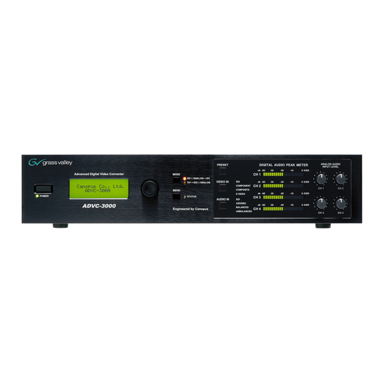
Chapter 2 - Basic Operations Part names and functions 1-1. ADVC3000 front panel The front panel of the ADVC3000 unit has the following controllers and indicators. Select dial PRESET button MODE button Turn the Select dial to choose the menu items, and... - Page 15 Chapter 2 - Basic Operations • MODE button Used to switch on the operation mode of the ADVC3000. Pressing the button will activate the Encode operation and Decode operation alternately. When “SDI/ANALOG DV” LED illuminates, ADVC3000 converts input SDI or analog signal to DV signal (DV Encode).
-
Page 16: Advc3000 Rear Panel
Chapter 2 - Basic Operations 1-2. ADVC3000 rear panel The rear panel of the ADVC3000 has the following connectors. COMPONENT VIDEO S-VIDEO Input and output connectors for S-Video signal. Input and output connectors for component video signal. COMPOSITE ANALOG AUDIO IN... - Page 17 Use a DV cable to connect the Use a DV cable to connect the Output connector for reference ADVC3000 to a DV device or a PC. ADVC3000 to a DV device or a signal (sync signal). (Bus power is not supplied.) NOTES - This unit will not work as an OHCI Hub with Canopus DV products.
-
Page 18: Dip Switch Settings
Chapter 2 - Basic Operations 1-3. DIP switch settings The rear panel of the ADVC3000 unit has the following DIP switches. Default SW3, SW4 settings may differ depending on the place of purchase. PHY SPEED S400 S200 Update Mode Normal... -
Page 19: Lcd Screen Displays
Chapter 2 - Basic Operations 1-4. LCD screen displays ADVC3000 has three main screens and an error status screen. Turn the Select dial to switch between the main screens and the error status screen. Pressing the MENU button displays the setting menu screen. - Page 20 Chapter 2 - Basic Operations (Continued) 1. Video input SDI ......Signal from the SDI connector is input. COMPONENT ....Signal from the component connector is input. S VIDEO .....Signal from the S-Video connector is input. COMPOSITE ....Signal from the composite connector is input. SG.......Color bar is output.
- Page 21 Chapter 2 - Basic Operations 6. On the Main screen 1: Input time code TC 00:00:03:22 ...For PAL/NTSC NDF (Non Drop Frame) * A colon is used between seconds and frames as a delimiter. TC 00:00:03;22 ...For NTSC DF (Drop Frame) * A semicolon is used between seconds and frames as a delimiter.
- Page 22 Chapter 2 - Basic Operations • In the DV SDI/ANALOG mode 1. DV Input 4. Deck status 5. On the Main screen 1: Input time code Displays the status of the deck. Displays the time code. 6. Audio monitor status 7.
- Page 23 Chapter 2 - Basic Operations 3. Audio format 48 k ......DV audio signal of 48kHz, 16bit audio is input. 44 k ......DV audio signal of 44.1kHz, 16bit audio is input. 32 k ......DV audio signal of 32kHz, 16bit or 12bit audio is input. ----- ......No signal is detected.
- Page 24 LTC ......ADVC3000 is acquiring the time code from TC input connector. auto ......ADVC3000 tries to acquire the time code from both DVITC of the SDI input connector and LTC and uses LTC if it is acquired and DVITC if LTC is not detected.
- Page 25 Chapter 2 - Basic Operations Error status screen This screen shows error messages. • When error is not detected • When error is detected COMPOSITEin/COMPONENTin/S VIDEOin/SDIin • In SDI/ANALOG DV mode Displayed when the video signal selected by the VIDEO IN button failed to be input. The LED does not fl...
-
Page 26: Connecting Devices
DV editing software is required to playback or capture video fi les for use on a PC or to record the fi le data onto tape. In addition, the PC should be equipped with an IEEE1394 connector. CAUTION When connecting a PC to the ADVC3000 unit, make sure that the PC’s power is turned off. - Page 27 DV editing software is required to playback or capture video fi les for use on a PC or to record the fi le data onto tape. In addition, the PC should be equipped with an IEEE1394 connector. CAUTION When connecting a PC to the ADVC3000 unit, make sure that the PC’s power is turned off.
-
Page 28: Importing Vcr Data To Your Pc
Analog When entering the data via DV editing software Speaker Monitor Press the MODE button on the front panel of the ADVC3000 to switch the mode to [SDI/ ANALOG DV]. Light Press Capture the data by using DV editing software. -
Page 29: Recording Pc-Edited Data Onto A Tape With Vcr
When outputting the data via DV editing software Speaker Monitor Press the MODE button on the front panel of the ADVC3000 to switch the mode to the [DV SDI/ANALOG]. Light Press Use the DV editing software to output your data. -
Page 30: Menu Setting Operations
Chapter 2 - Basic Operations Menu setting operations 3-1. Menu screen operations Press the Select dial or MENU button to go to the setting menu screen. Setting menu is displayed on LCD Press Turn the Select dial to choose the menu item to set. Turn Choose the menu item... - Page 31 Chapter 2 - Basic Operations Turn the Select dial clockwise to proceed to the setup menus. Turn Turn the Select dial counterclockwise to go back the setting menus. Turn (Continued on the next page)
- Page 32 Chapter 2 - Basic Operations (Continued) After selecting the menu item with the Select dial, turn the Select dial to change its setting. If the menu item chosen has a sub-menu, press the Select dial to display the sub-menu. The item has been chosen in step 2. Press the Select dial.
-
Page 33: Presetting The Video/Audio Input
Chapter 2 - Basic Operations 3-2. Presetting the video/audio input 4 combinations of video and audio input* can be stored in “001 input preset 1” to “004 input preset 4” and can be recalled by one press of the button. * In addition to video and audio input, remote A and B setting (501 9P remote) and DV audio format (201 DV audio encode) setting can be stored in preset 1 to 4. - Page 34 Chapter 2 - Basic Operations (Continued) Turn the Select dial to choose the desired number (001 to 004) and press the Select dial. Turn and press • You can make settings so that only some preset items will be recalled (unnecessary items can be skipped).
- Page 35 Chapter 2 - Basic Operations Recalling the settings Press the PRESET button. Each time you press the button, settings 1 to 4 are recalled in turn. Press...
-
Page 36: Setting Parameters
Chapter 2 - Basic Operations 3-3. Setting parameters 000 - 099 AV input settings Video/audio input preset ---------------------------------------------- 001 input preset 1 -------------- 38 002 input preset 2 -------------- 38 003 input preset 3 -------------- 38 004 input preset 4 -------------- 38 100 - 199 Video input/output settings Video input adjustment settings ------------------------------------- 101 video input adj. - Page 37 Chapter 2 - Basic Operations 400 - 499 External synchronization settings External synchronization ---------------------------------------------- 401 ext. sync -------------------- 54 External synchronization confi guration ---------------------------- 402 ext. sync conf. ------------- 54 Audio out delay setting ------------------------------------------------ 403 audio out delay ------------ 55 External synchronization source settings ------------------------- 404 ext.
-
Page 38: Video/Audio Input Preset
Chapter 2 - Basic Operations 001 input preset 1 Stores 4 combinations of video and audio input. Each time you press the PRESET button, preset 1 to 4 is 002 input preset 2 recalled in turn. (Refer to page 33 for details.) 003 input preset 3 004 input preset 4 Video/audio input preset... -
Page 39: Video Input Adjustment Settings
Chapter 2 - Basic Operations 101 video input adj. Adjusts the video quality of the input video. Video input adjustment settings * According to the settings of the video standard or video input, some menu items may not be available and do not appear in the display. 1. - Page 40 Chapter 2 - Basic Operations (Continued) saturation Adjusts color strength. The smaller the value is, the lighter the color is; the larger, the darker. You can reproduce complete gray-scale with minimum value 0 (zero). Set specifi ed numerical value between 0 and 255. (Factory default: For composite/S video) NTSC 0 IRE: 128, 7.5 IRE: 138, PAL:128, SECAM:128 (Factory default: For component)
- Page 41 Chapter 2 - Basic Operations (Continued) 2D chroma NR Eliminates the noise on the color component by non-linear noise extract fi lter. none Disables the 2D chrominance noise extract. (Factory default) Enables low 2D noise extract fi lter. middle Enables medium 2D noise extract fi lter. high Enables high 2D noise extract fi...
- Page 42 Chapter 2 - Basic Operations (Continued) W adaptation Sets the adjustment volume for white gain limit. As the limit volume is larger, white level gain will be adjusted to lower. level 1 (Factory default) level 2 to 4 white threshold Sets the level of luminance (brightness) to which white gain will be lowered.
-
Page 43: Video Output Adjustment Settings
Chapter 2 - Basic Operations 102 video output adj Adjusts settings on output video. Video output adjustment settings LCD display Press the Select dial to display the sub-menu. In the sub-menu, turn the Select dial to adjust the level or setting. Sub-menu Specifi... -
Page 44: Video Output Auto-Off Settings
Chapter 2 - Basic Operations 103 Vout auto-off Specifi es the output connector that automatically stops the video output in SDI/ANALOG DV mode. When the reference signal is not used, set this option to [auto-off] to prevent a looped connection with a connected device. -
Page 45: Dv Output Auto-Off Setting
Chapter 2 - Basic Operations 104 DVout auto-mute Selects the conditions where ADVC3000 automatically stops the DV stream in SDI/ ANALOG DV mode. DV output auto-off setting LCD display Does not stop DV stream. Stops DV stream automatically when video is not input. (Factory default) -
Page 46: Dv Output Aspect Ratio Settings
Chapter 2 - Basic Operations 105 DV aspect info Specifi es the aspect ratio for the DV stream that ADVC3000 outputs in SDI/ANALOG DV mode. DV output aspect ratio settings LCD display For NTSC Sets the DV stream in 4:3 aspect ratio. (Factory default) Sets the DV stream in16:9 aspect ratio (letter box). -
Page 47: S-Video Output Aspect Ratio Setting
Chapter 2 - Basic Operations 106 Sout aspect info Specifi es the aspect ratio for the S-Video that ADVC3000 outputs. S-Video output aspect ratio setting LCD display Sets the S-Video in 4:3 aspect ratio. (Factory default) Sets the S-Video in16:9 aspect ratio (letter box). -
Page 48: Video Standard Settings
Chapter 2 - Basic Operations 107 video standard Specifi es the video standard. Once you have changed the video standard settings (or the setup level), you are prompted to turn the power off to make the new setting take effect. Video standard settings LCD display Press the Select dial to display the sub-menu. -
Page 49: Video Output Synchronizing Signal Settings
(Factory default: 0) 111 Vout audio delay Sets the amount (in unit of milliseconds) to increase/ decrease the ADVC3000 audio output delay relative to the video output, when the external sync is enabled in SDI/ANALOG DV mode. *When “108 DVout frame sync” is set to disable, the DV output data is not delayed. -
Page 50: Dv Audio Encode Setting
Chapter 2 - Basic Operations 201 DV audio encode Specifi es the DV audio format and channel in SDI/ ANALOG DV mode. DV audio encode setting LCD display Encodes audio input CH1 and CH2 in the audio format of 48kHz/16bit. (Factory default) Encodes audio input CH1, CH2, CH3, and CH4 in the audio format of 32kHz/12bit. -
Page 51: Balanced Audio Input/Output Level
Chapter 2 - Basic Operations 203 audio level Specifi es the input/output level of the Balanced audio (XLR). Balanced audio input/output level LCD display Press the Select dial to display the sub-menu. In the sub-menu, turn the Select dial to move the cursor, and press the Select dial again to change the input/output level of the channel that you select. -
Page 52: Balanced Audio (Xlr) Input Termination
Chapter 2 - Basic Operations 205 600 ohm term. Sets the termination at the balanced audio (XLR) input connector. Balanced audio (XLR) input termination LCD display Press the Select dial to move the cursor, and press the Select dial to change ON/OFF alternately. termination High impedance 301 TC source... -
Page 53: Dvitc Settings
Chapter 2 - Basic Operations 302 VITC insert line Selects the line at which DVITC is inserted in SDI output or the line at which DVITC is read from SDI input. DVITC settings LCD display Press the Select dial to display the sub-menu. In the sub-menu, turn the Select dial to select the line. -
Page 54: External Synchronization
* The “advanced” setting is only available when DV signal is output from an IEEE1394 connector compliant with PC OHCI specifi cations. For supported PC operating systems, please refer to our website. * When the ADVC3000 is connected to Canopus ADVC units through DV connectors, do not set to the “perfect sync mode”. -
Page 55: Audio Out Delay Setting
Chapter 2 - Basic Operations 403 audio out delay Sets the amount (in unit of milliseconds) to increase/ decrease the ADVC3000 audio output delay relative to the video output, when the external sync is enabled in DV SDI/ANALOG mode. Audio out delay setting LCD display Set specifi... -
Page 56: Color Bar Output
Chapter 2 - Basic Operations (Continued) Enables the deck control from the remote B connector. 601 SG output Selects the color bar output mode. Color bar output LCD display Does not output color bar. (Factory default) Outputs color bar. * External synchronization function cannot be used. * Free-run time-code is output. -
Page 57: Ieee1394 Clock Adjustment
Chapter 2 - Basic Operations 701 1394 clock adj. Sets the IEEE1394 system clock. IEEE1394 clock adjustment LCD display In most cases, factory default settings (127) should be used. (Factory default: 127) 702 local disable Enables/Disables the MODE button , VIDEO IN button, AUDIO IN button and PRESET button. -
Page 58: Resample Fi Lter Setting
Chapter 2 - Basic Operations 704 resample fi lter Selects the type of horizontal resampling fi lter for Cb/ Cr signal. (NTSC only) Resample fi lter setting LCD display Sets normal modulus. (Factory default) Sets modulus that emphasizes anti-alias. Sets modulus that emphasizes frequency characteristic. 705 AV/C transaction Selects the type of AV/C transaction at the time AV/C command is received. -
Page 59: Maximum Data Rate Setting
Chapter 2 - Basic Operations 706 data rate cap. Selects the maximum communication speed of the “dr cap” fi eld of “iMPR/oMPR” at the time of booting and setting change. Once you have changed this setting, you are prompted to turn the power off to make the new setting take effect. -
Page 60: Lcd Backlight Illuminating Period Settings
Chapter 2 - Basic Operations 707 LCD backlight Sets the backlight lighting period of the front panel LCD. LCD backlight illuminating period settings LCD display Press the Select dial to display the sub-menu. In the sub-menu, turn the Select dial to select the lighting period. sub-menu Lights for 5 seconds after operating the front panel. -
Page 61: Save Settings
Chapter 2 - Basic Operations 901 save settings Saves the current setting to the user 1 to 3 settings. Save settings 1. Turn the Select dial to select user 1 to 3, and press the Select dial. user1: save the current setting as user 1 user2: save the current setting as user 2 user3: save the current setting as user 3 2. -
Page 62: System Version
Chapter 2 - Basic Operations 903 system version This item contains sub-menus displaying fi rmware version numbers. System version LCD display Press the Select dial to display the sub-menu. In the sub-menu, turn the Select dial to choose the sub-menu item. - Page 63 3000 Chapter 3 Appendix This chapter provides supplementary information regarding the ADVC3000 operations. - Specifi cations...
-
Page 64: Chapter 3 - Appendix 1 Specifi Cations
Chapter 3 - Appendix Specifi cations Composite NTSC (525/59.94i), PAL (625/50i) S Video * SECAM is available only for input. In that case, PAL signal is output. Video signal Component 525/59.94i, 625/50i SD-SDI/DV * 59.94i 50i conversion is not possible. IEEE1394 4 pin x 1, IEEE1394 6 pin x 1(Without bus power supply) DV input/output... - Page 65 Chapter 3 - Appendix BNC x 2 (INPUT and LOOP THROUGH, automatic 75 Reference input B.B input termination) BNC x 1 Reference output B.B output * Does not synchronize with video output. RS-422A (D-sub 9 pin) x 2 REMOTE output Command converter for AV/C RS422A Input level adjusting volume (CH1 to CH4)
Need help?
Do you have a question about the ADVC3000 and is the answer not in the manual?
Questions and answers