Table of Contents
Advertisement
Quick Links
Advertisement
Table of Contents

Subscribe to Our Youtube Channel
Related Manuals for Keithley 2230 Series


Summary of Contents for Keithley 2230 Series
- Page 1 Series 2230 Triple-Channel DC Power Supply Quick Start Guide...
-
Page 2: Safety Precautions
For maximum safety, do not touch the product, test cables, or any other instruments while Keithley products are designed for use with electrical signals that are measurement, control, power is applied to the circuit under test. ALWAYS remove power from the entire test system... - Page 3 If you are using a test fi xture, keep the lid closed while power is applied to the device under test. Keithley. Standard fuses with applicable national safety approvals may be used if the rating and Safe operation requires the use of a lid interlock.
- Page 4 Power and environmental ratings For indoor use only. 0 °C to 40 °C, full accuracy with maximum 2230-30-3 AC power input level: Power supply Operating temperature 80% relative humidity at up to 40 °C, 110 V setting: 99 V AC to 132 V AC; noncondensing 220 V setting: 198 V AC to 264 V AC;...
- Page 5 Introduction The Models 2230-30-3, 2230-30-6, and 2230-60-3 The Series 2230 models are listed in the following table. Triple-Channel Programmable DC Power Supplies provide you with high resolution, high accuracy, and high stability. Model number Description They provide resolution up to 1 mV and 1 mA to meet 2230-30-3 Triple-Channel Programmable DC Power Supply, the needs of a variety of applications.
-
Page 6: Unpack And Inspect The Instrument
Unpack and inspect the instrument You should have received your 2230-30-3, 2230-30-6, or To unpack and inspect the instrument: 2230-60-3 power supply with the following accessories: 1. Inspect the box for damage. • Calibration certificate, part number 001165500 2. Open the top of the box. •... -
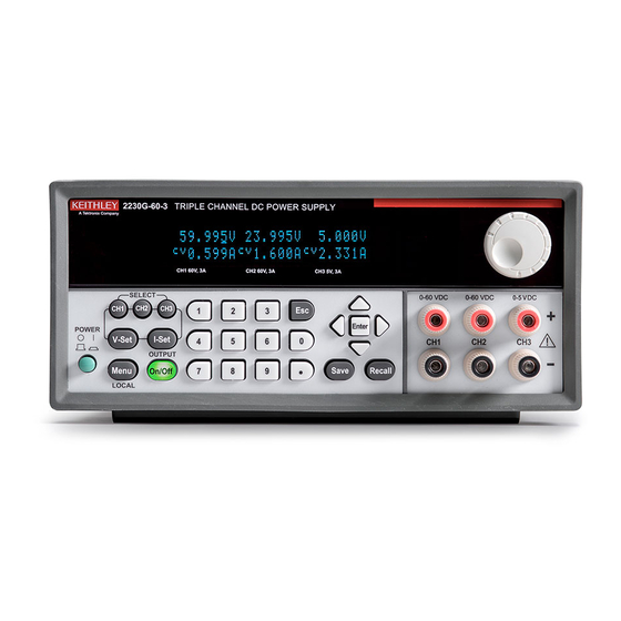
Page 7: Front Panel Overview
Front-panel overview Number Description Vacuum fluorescent display (VFD) 2230-30-6 Navigation wheel: Turn the navigation wheel to increase or decrease a value or to scroll through the menus after pressing the Menu key. When you have selected the menu item or value you want, press the Enter key to save your setting Output terminals Up, down, left, and right arrow keys, Enter, Save, and... -
Page 8: Keyboard Overview
Keyboard overview Turn the output of all enabled channels on or off. When you turn on the output, the CC or CV indicators are visible on the display. When you turn off the output, the SV The keyboard of the Series 2230 power supply is shown in the indicators are visible on the display. SV indicates that the following figure. display is showing each channel’s programmed settings. through numeric keys. -
Page 9: Rear Panel Overview
Rear-panel overview Number Description Vent and fan All 2230 power supply models have the same rear panel. The rear panel is shown in the figure below. Descriptions of RS-232 communication interface connector the numbered items follow the figure. USB communication interface connector AC power input socket (including fuse) Remote sense and output terminals Connect... -
Page 10: Front-Panel User Interface Overview
Front-panel user interface overview Menu screen overview The front-panel user interface gives you quick access to When you press the key on the front panel, the measurement settings, system configuration, instrument system menu screen is displayed. status, and other functions. The following options are displayed: Home-screen overview •... -
Page 11: Connect The Instrument
42.4 V or 60 V dc for equipment rated for dry PEAK hazardous areas. locations. Keithley Instruments products are only rated for dry locations. • Provide training to all users of the system so that they understand all potential hazards and know how to protect •... -
Page 12: Install The Instrument
Connect line power NOTE Series 2230 power supplies operate at 110 V to 120 V or To keep users safe, always read and follow all safety warnings 220 V to 240 V with a frequency of 50 Hz or 60 Hz. Make provided with each of the instruments in your system. - Page 13 To power on the 2230-30-3: WARNING 1. Make sure the front-panel power switch is in the off (O) position. Do not replace detachable mains supply cords with 2. Properly set the 110 V/220 V selector switch on the inadequately rated cords. Failure to use properly rated bottom of the instrument.
- Page 14 5. Disconnect any devices under test (DUTs) from the 1. Make sure the front-panel power switch is in the instrument before turning the instrument on. (0) position. 6. Turn on the instrument by pressing the POWER switch 2. Properly set the 110 V/220 V selector switch on the on the front panel to the on (|) position.
-
Page 15: Connections For Testing
Connections for testing Before making the connections, prepare the wires as described in the following table. Connection Specification Front-panel output terminals AWG 22 to AWG 14 Sense terminals AWG 22 to AWG 14 CAUTION The wire must be heavy enough that it does not overheat while carrying the short-circuit current. - Page 16 Local sense connection The local sense connection is used for basic operations when maximum precision is not required. Keep the wire as short as possible to reduce wire resistance. If you want higher measurement precision, use a remote sense connection. To connect the DUT to the power supply using local sense: 1.
-
Page 17: Remote Sense Connection
Remote sense connection CAUTION You can use the remote sense connection for better measurement precision. To ensure the stability of the system, use shielded twisted pair cable between the remote sense terminals To connect the DUT to the power supply using remote and the instrument under test. -
Page 18: Basic Settings
Basic settings 3. Use the numeric keys, the navigation wheel and the up, down, right, and left arrow keys to set the current limit. 4. Press the Enter to confirm the setting. Set the voltage output or voltage limit for a specific channel Save the setups You can set the voltage limit from 0 V to the specified You can store up to 36 different setups in memory. Each maximum voltage. -
Page 19: Channel Settings
Channel settings Track Enable channels You can set channel 1 (CH1) and channel 2 (CH2), channel 2, and channel 3 (CH3), and all three channels You can enable or disable each channel using the menu. If a combined to tracking mode. When CH1 and CH2 tracking is channel is disabled, it remains off when the output is turned on. on, channel 1 and channel 2 respond relative to one another when adjustments in voltage are made. - Page 20 Example of setting up CH1/CH2 tracking mode: To disable the tracking function: 1. Press the CH1 key. 1. Press the Menu key. 2. Press the V-Set key and enter the voltage value for 2. Use the arrow keys to select Track. channel 1.
- Page 21 6. Press the Enter key. The screen returns to meter mode. NOTE Verify that the Series indicator is displayed, replacing the channel 2 voltage and current readings. This indicates that the power supply is in the V1+V2 series state. The The wiring between the power supplies drives the accuracy of total output voltage is displayed on Channel 1.
- Page 22 Example: Combine I1+I2 in parallel 2. Press the Menu key. 3. Use the arrow keys to select Combine. To combine channel 1 and channel 2 when the outputs 4. Press the Enter key. are wired in parallel: 5. Press the down arrow key to select I1+I2 Parallel. 1.
-
Page 23: Next Steps
It provides detailed information about all features of the What should I do if the power supply does not read the instrument. voltage or voltages I have set? You can also visit the Keithley Instruments website, tek.com/ • Make sure that the rear-panel mating connector with the... - Page 24 Contact information: 1-800-833-9200 For additional contacts, see tek.com/contact Find more valuable resources at TEK.COM. Copyright © 2022, Tektronix. All rights reserved. Tektronix products are covered by U.S. and foreign patents, issued and pending. Information in this publication supersedes that in all previously published material.
Need help?
Do you have a question about the 2230 Series and is the answer not in the manual?
Questions and answers