Table of Contents
Advertisement
Quick Links
Advertisement
Table of Contents

Summary of Contents for Graphtech Ghost
- Page 1 Be the band. Hexpander MIDI Interface Acousti-Phonic Pre-amp User Guide...
-
Page 2: Table Of Contents
Sample Control Layouts ...........14 ® ......16 lanninG hOst nstallatiOn ® Locating Ghost Components.......17 Pots and QuickSwitches .........17 Extension Harness *optional*......18 Hexpander and 13-pin Jack........19 Acousti-phonic & 9v battery.........20 Acoustic volume: convert, stack, or drill?...21 Convert Mag Tone Pot to Acoustic Volume..21 Replace a Pot with a Stacked Pot......22... - Page 3 Hexpander 13-pin jack..............32 Enlarging the control cavity........39 Curving the Jack Plate..........39 Acousti-Phonic Stereo switched Jack (no routing required)..40 9v battery..............40 Installing Ghost® Modular Components Saddles................41 Pickup wires...............41 Color code ..............42 Signal/ground color code ........43 Summing board ............43 Extension harness *optional*......43 Seating and setup............44...
- Page 4 Program Up/Down (orientation) *optional* ...52 QuickSwitch for MIDI/both/guitar *opt.*..53 MIDI volume *optional*.........54 Mag-to-pin-7 Harness *optional*......55 Acousti-Phonic.............56 Acoustic volume and magnetic input....56 Acoustic volume with Mid/Dark switch *opt.*..58 Stereo switched output jack.........59 QuickSwitch for mag/both/acoustic *opt.*..60 Connecting Pickups to the Acousti-phonic..61 Gain Adjustment............61 Battery Power Connecting the Battery.....62 Piggyback –...
-
Page 5: O Verview Of The G Host ® System
Of the hOst system The ghost® system is a set of modular components that adds acoustic or MIDI capability to your guitar without altering your magnetic pickup tone. Ghost® pickups encapsulated in bridge saddles provide the input signal for the ghost® system, leaving your magnetic pickups unchanged. -
Page 6: Will It Work With My Guitar
Will it work with my guitar? The ghost® system is designed to fit most guitars and basses. Installing it requires replacing the saddles on your bridge with compatible ghost® pickup saddles. Graph Tech makes these for Strat and Tele style guitars,... -
Page 7: Introducing Modular Components
Introducing modular components Modular means that the ghost® system’s components can be plugged into each other in different combinations to create different systems. Once you’ve selected pickup saddles to fit your guitar, these can be connected to the Acousti-Phonic™ for authentic acoustic sound from your electric guitar, or to the Hexpander™... -
Page 8: Output Options
Output options Replacing the 1/4” output jack with the Stereo Switched Jack supplied with the Acousti-Phonic permits the output of two signals, magnetic and acoustic, through one jack. The 13- pin jack installed with the Hexpander carries the hexaphonic signals for MIDI conversion, and can also carry the magnetic and acoustic signals so that a 1/4”... -
Page 9: Mono And Stereo Modes
Mono and Stereo Modes The Acousti-Phonic detects whether you’ve inserted a stereo or mono plug into the 1/4” jack and automatically switches to Stereo (separate) or Mono (blended) mode. In Mono mode, the acoustic and magnetic signals are blended together in the Acousti-Phonic and delivered together on the Tip contact. - Page 10 In Stereo mode, the acoustic signal is on the Ring contact, and the magnetic signal appears on the Tip contact so that you can process these signals separately using a stereo-to-two-mono Y-cable. For example, run your magnetic pickups through a crunchy guitar amp and your acoustic sound through a clean P.A.
-
Page 11: Quickswitch Functions
QuickSwitch functions Two three-position switches provide fast, intuitive switching between all possible sound combinations: any one sound, any combination of two, or all three at the same time. Without the switches, you can mute any of the signals by turning the volume down, but with a QuickSwitch you can instantly turn a sound off, or on at the volume level you have chosen. -
Page 12: Hexpander Only And Mag-To-Pin-7
Hexpander only and mag-to-pin-7 This option lets you run your acoustic and/or magnetic signals down pin number 7 of the 13-pin cable plugged into the Hexpander, so you don’t need a 1/4” cable attached to your guitar. Most MIDI converters have two 1/4” outputs on the back -- one for MIDI and one for this pin-7 signal, so you can still run your mags to your electric guitar amp. - Page 13 When the Hexpander is piggybacked on the Acousti-Phonic, the mag-to-pin-7 harness is not necessary because Acousti-phonic passes the acoustic and/or magnetic signals to the Hexpander. But when you install the Hexpander only, adding the mag-to- pin-7 harness and an acoustic volume control (250K or 500K audio pot) provides this feature in the absence of the Acousti- Phonic.
-
Page 14: Sample Control Layouts
Sample Control Layout(s) Here are examples of possible control layouts on Strat- style and Les Paul-style guitars. The ghost® system is not just for Strats and Les Pauls, and other layouts are possible, as are custom controls and output options. - Page 15 MAGNETIC VOLUME MAGNETIC TONE QUICKSWITCH ACOUSTIC MIDI VOLUME VOLUME * requires rewiring 3-way switch for master volume and tone BRIDGE VOLUME ACOUSTIC VOLUME BRIDGE TONE QUICKSWITCH NECK NECK TONE VOLUME...
-
Page 16: Lanning Our Host Nstallation
® i lanninG hOst nstallatiOn Adding a ghost® system to your instrument begins with careful planning. Decide which optional controls suit the music you make, and choose locations that are convenient for you. To begin, plug the components into each other and lay them out on top of the guitar to decide the location of each component. -
Page 17: Locating Ghost Components
Locating Ghost® Components The ghost® boards are small -- about the size of a match box -- so they will fit inside the control cavity of most guitars without any routing. You must decide which arrangement is best for your particular instrument. -
Page 18: Extension Harness *Optional
Extension harness *optional* Like an extension cord, it allows you to locate the pickups further away from the ghost® boards. For some installations this may be necessary, while for others it may make the installation neater or more convenient. It can be used with both the Hexpander and the Acousti-Phonic. -
Page 19: Hexpander And 13-Pin Jack
Hexpander and 13-pin Jack The 13-pin jack that comes with the Hexpander can be mounted on the edge, on the front, or on the back of the instrument. Edge- mounting requires a rectangular hole and the included 13-pin jack plate, while front and rear mounting can either use the jack plate or a round hole. -
Page 20: Acousti-Phonic & 9V Battery
Acousti-Phonic & 9v battery The 9v battery that powers the Acousti-Phonic may require some routing to fit it inside your guitar. Consider these possible locations for the battery: the side wall of the cavity, the back wall behind the pots, or stuck to the control cavity cover plate. The Hexpander does not require a 9v battery because it will get power from the MIDI converter through the 13-pin jack. -
Page 21: Acoustic Volume: Convert, Stack, Or Drill
The Acousti-Phonic requires a pot to control the level of the acoustic sound, but none is included. Choose one of these three methods to add an acoustic volume to your guitar for the ghost® system: Convert Mag Tone Pot to Acoustic Volume For the basic installation, convert one of your tone pots into the acoustic volume using the supplied wiring harness. -
Page 22: Replace A Pot With A Stacked Pot
Replace a Pot with a Stacked Pot If you prefer to keep your tone control, you can also avoid drilling a hole for the acoustic volume pot by replacing one of your pots with a “stacked” or “concentric” pot*. You may choose to group the magnetic and acoustic volume pots together on the concentric pot, or group your magnetic volume and tone on the concentric and convert one of the single pots... -
Page 23: Drill A Hole And Add A Pot
You can purchase a 250K or 500K audio-taper potentiometer*, or you can get the ghost® Acoustic Volume with Mid/Dark Switch from Graph Tech either as a push-on/push-off pot or as a toggle switch. -
Page 24: Strats And Teles
QuickSwitch because they make connections differently inside. Hollow bodies have plenty of room to add the ghost® system, but it can be difficult to work inside them (you may feel like you’re making... -
Page 25: Outing Rilling And Otching
13-pin jack. OutinG rillinG OtchinG Some modification of the guitar body may be required to install the ghost® system in your instrument. The modification required depends on the design of your instrument, and the ghost® components you’ve chosen to install. -
Page 26: Tools Required
Required Tools • Electric drill and 5/16” bit (12” long recommended) for drilling hole between cavities and starting 13-pin jack hole; 9/32” bit for adding optional pots; 5/64” bit for 13-pin jack mounting plate holes; and 1/4” bit for installing optional QuickSwitches •... - Page 27 Required Tools Optional Tools...
-
Page 28: Reversible Installation
Reversible installation If you have a vintage instrument and its value may be affected by modifications, or if you want to try the ghost® system before committing to the modifications required, you can do a reversible installation. A ghost® system installed this way may not be as neat or as convenient, but you can return the instrument to its original condition if you choose to remove the ghost®... -
Page 29: Notching The Pick Guard Or Pickup Ring
Saddles Notching the pick guard or pickup ring The wires on the ghost® saddles must go into the control cavity to plug into the Hexpander or into the Acousti-Phonic via the Summing Board and Dual Connector Cable. Cutting six, small... -
Page 30: Slotting The Base Plate *Optional
Slotting the base plate *optional* Slotting the base plate of the bridge is an alternative to notching the pick guard or pickup ring. It will make the Ghost® wires practically invisible by running them into the guitar body through slots cut in the bridge. The bridge will have to be removed from the guitar and taken to a machine shop that can cut the slots precisely in the steel. -
Page 31: Drilling Between Control Cavities
Drilling between control cavities In some installations, you may have to drill a hole to route the wires between cavities in the instrument to pass the pickup wires through. This hole will have to be large enough that the connectors on the pickups can be passed through easily. We recommend 5/16”... -
Page 32: Hexpander 13-Pin Jack
Hexpander 13-pin jack For mounting the Hexpander output on the edge of the instrument, the small PC board with the 13- pin jack requires a rectangular mounting hole in the body. Choose a location for this hole, checking that there is room for a 1-1/8” (30mm) deep cavity, and that the ribbon cable will reach from here to the main Hexpander board. - Page 34 This space intentionally left blank for reverse of template...
- Page 35 Tape the template to the edge of the instrument, and mark the center of the circles onto the guitar by tapping through the template into the paint using a center punch and a small hammer. Using an Olfa or X-Acto knife, slice through the template along the edges of the inner rectangle, etching lines in the paint to mark the edges of the mounting hole.
- Page 36 Using a 1/16” bit, drill the four holes for the mounting screws in the outer most marks to a depth of 1/4”. Make these holes perpendicular to the surface. Using a 1/8” bit, drill the inner four marks to a depth of 1-1/8”, defining the four corners of the mounting hole.
- Page 37 Using 3/8” bit, drill holes within inner rectangle to remove most of the wood in the cavity.
- Page 38 Using a router, a Dremel rotary tool, or a chisel, remove the remaining wood to edges of the marked rectangle, to a depth of 1-1/8”. Be careful not to enlarge the mounting hole beyond the lines, as the jack plate fits quite precisely to these dimensions.
-
Page 39: Enlarging The Control Cavity
Enlarging the control cavity In most cases, no enlargement of the cavity is required to install the main Hexpander board. Guitars with small cavities like Telecasters, or guitars with a lot of electronics already installed may require some routing to make room for the Hexpander. Curving the Jack Plate The jack plate can easily be curved to conform to the surface of the edge of the instrument where the 13-pin jack is to be mounted. -
Page 40: Acousti-Phonic
Acousti-Phonic Stereo switched Jack (no routing required) Usually, no routing is required to replace the 1/4” jack in your instrument with the 1/4” Stereo Switched Jack that comes with the Acousti-Phonic. In some instances, the jack is recessed in a hole that is too small. -
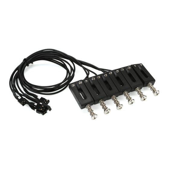
Page 41: Installing Ghost® Modular Components Saddles
ODular OmPOnents Saddles Ghost® saddles are made of our patented String Saver composite material which is rugged and durable. The pickup wires, however, are delicate and must be handled gently during installation. Pickup Wires Route the wires so that they are not flexed sharply or excessively, and are not abraded by the edges of holes they must pass through. -
Page 42: Color Code
Color code The ghost saddle pickups are all identical and can be installed in any string position. If you are installing the Hexpander and you must feed the wires through a hole from one cavity to another, you may need to mark the wire ends to be able to tell which is which. -
Page 43: Signal/Ground Color Code
Extension harness *optional* Use the colored wire on the Extension Harness to make sure it is oriented properly, extending the pickup wires without reversing them. The blue wires of the pickups must be connected to the ground side on the ghost® boards. -
Page 44: Seating And Setup
Seating and setup Ghost® saddles are designed to be set up just like the regular saddles they replaced. For optimum performance, make sure that both height adjustment screws are set so that the saddle pickup is level (Strat, Tele, and PRS), and that the string is not obstructed in any way as it passes over or through the saddle. -
Page 45: Hexpander
Hexpander Locate the Hexpander where it can accept plug-in connections from the 13-pin jack, the saddle pickups, and the battery and options if applicable. When piggybacking with the Acousti-Phonic, mount the pair of boards on the cavity wall or rear cover plate using the self-adhesive foam supplied with the Acousti-Phonic. -
Page 46: 13-Pin Jack
13-pin jack After the mounting hole has been routed and the 13-pin jack plate has been curved to conform to the edge of the guitar (see instructions in the Routing, Drilling, and Notching section of this manual) bolt the 13-pin jack plate to the 13-pin jack using the supplied nuts, bolts, and lock washers. -
Page 47: Connecting The 13-Pin Jack
Connecting Hexpander to 13-pin jack Plug the Interface Wiring Harness (ribbon cable) into the header pins on 13-pin jack; this connection is ‘keyed’ (one pin missing, one hole blocked) so that it can only be plugged in correctly. Feed the harness through the mounting hole and into the control cavity where the Hexpander will be located. -
Page 48: Traktion Switch
Traktion Switch The Traktion Switch optimizes the output of the Hexpander for use with either Roland or Axon MIDI converters. Reach into the slot on the 13-pin jack plate with a toothpick to slide this tiny switch to match the converter you’re using. If your converter is a Yamaha or another brand, try both positions and use the one that works best. -
Page 49: Connecting Pickups To The Hexpander
Connecting Pickups to the Hexpander Plug the six blue and silver wires from the pickups into the Hexpander on the pin pairs labeled 1, 2, 3, 4, 5, 6, with the silver wires nearest the labels and the blue wires on the ground row, according to the order for your instrument: 6 string guitar EBGDEA = 123456... - Page 50 exPanDer OnnectiOn iaGram String Assignments for Guitar and Bass Piezo Number of Strings: Saddles hi-E VOLUME lo-E lo-E lo-B lo-E lo-B (not Hex) MIDI violet VOLUME yellow blue Program Quick Switch Switch 1/4” Stereo white black Jack MIDI acoustic both down...
- Page 51 Hexpander-only and Dual Board Connector “Piggyback” installations 13-pin Hexaphonic Output Jack ghost Hexpander MIDI interface board (fits hole: 1” x 1-1/4” x 1-1/4” deep) (dimensions: 1-1/8” x 1-5/8” x 1/2”) HEADER PINS Interface Wiring Harness SIGNAL ROW (all colored wires)
-
Page 52: Program Up/Down (Orientation) *Optional
Program Up/Down Switch *optional* Drill a 1/4” hole in the pick guard or guitar top and mount the switch using the nuts and washers supplied. Orient the switch as desired: pushing the toggle towards the violet wire scrolls up, and towards the yellow wire scrolls down. Plug the connector into the Hexpander on the rows marked S1 and S2 with only the black wire on the ground row. -
Page 53: Quickswitch For Midi/Both/Guitar *Opt
QuickSwitch for MIDI/both/guitar *optional* Drill a 1/4” hole in the pick guard or guitar top and mount the QuickSwitch using the nuts and washers supplied. Orient the switch according to your preference, using the colors of the wires soldered onto the switch to indicate which direction is which. Plug the QuickSwitch into the second row of the Hexpander on the pins marked MM and AM to select MIDI/both/guitar. -
Page 54: Midi Volume *Optional
MIDI volume pot *optional* Use an existing hole, or drill a new 9/32” hole in the pick guard or guitar top and mount the pot using the nuts and washers supplied. Plug the MIDI volume pot connector (red, white, and black wires) into the Hexpander on the rows marked VO and VI. -
Page 55: Mag-To-Pin-7 Harness *Optional
Mag-to-pin-7 Harness *optional* Plug the Mag-to-pin-7 harness into the first row of the Hexpander, nearest the edge of the board. It will span the pins labeled PMGVM, with the colored wires nearest the labels and the black wires on the ground row. Piezo Volume Hexpander Mag Volume... -
Page 56: Acousti-Phonic
Acousti-Phonic Locate the Acousti-Phonic where it can accept plug-in connections from the 1/4” jack, the saddle pickups, the battery, and options if applicable. Attach it, using the self adhesive foam tape on the back, to the side or back of the control cavity or to the inside of the cover plate. Acoustic volume and magnetic input The Basic Acousti-Phonic does not include a volume pot, but instead a wiring harness is provided to convert one of your tone... - Page 57 Piezo Volume Acousti-phonic 250k or 500k GHST audio taper Mag pickups Mag Volume To convert your tone control to an acoustic volume control, begin by unsoldering and removing any wires or components attached to the tone pot. Solder the purple, yellow, and black wires to the pot according to the diagram.
-
Page 58: Acoustic Volume With Mid/Dark Switch *Opt
Acoustic volume with Mid/Dark switch *optional* This switch selects either the EQ’d ghost® acoustic sound, or a second EQ curve with a boost in the mid range. It can be installed either as a mini-toggle switch, or as a switch incorporated in a pot. -
Page 59: Stereo Switched Output Jack
Stereo Switched Output Jack Solder the Output Jack Harness (red, white, blue, two blacks) to the supplied Stereo Switched Output Jack, cutting the wires to a reasonable length for your installation. The second black wire can go to the same lug as the first, or be used as a bridge ground if necessary. -
Page 60: Quickswitch For Mag/Both/Acoustic *Opt
QuickSwitch for mag/both/acoustic *optional* Drill a 1/4” hole in the pick guard or guitar top and mount the QuickSwitch using the nuts and washers supplied. Orient the switch according to your preference, using the colors of the wires soldered onto the switch to indicate which direction is which. -
Page 61: Connecting Pickups To The Acousti-Phonic
Connecting Pickups to Acousti-Phonic Plug the six blue and silver wires from the pickups into the Summing Board with all the blue wires on the same side and all the silver wires on the other. Plug the dual connector into the Acousti-phonic on the pins marked PIN (pickup in) with the dark blue wire on the ground, away from the label. -
Page 62: Battery Power Connecting The Battery
Battery Power A battery is required to power the Acousti-Phonic. The magnetic signal has to go through the Acousti-Phonic for blending purposes, so if the battery is removed or dead, there will be no output from the 1/4” jack, not even magnetic pickups. In normal use this battery lasts 500 hours, which means changing it twice a year will ensure that it never goes dead. - Page 63 Plugging this in incorrectly may damage the ghost® boards. The battery harness connector spans the two pin rows labeled PWR (power) and BAT (battery).
- Page 64 cousti phonic onnection iAgrAm Piezo Saddles Summing Board yellow purple VOLUME PIEZO VOLUME black black green RING black* 1/4” Stereo blue Switched Jack white black power for active pickups only (unused red wire if no active mag pickups) 9v Battery Clip...
- Page 65 SIGNAL ROW (all colored wires) piezo gain Dual Connector ghost Acousti-phonic pre-amp board (dimensions: 1-1/8" x 1-5/8" x 1/2") black* The harness for the Stereo Switched Jack has a second black ground wire that can be used as a bridge ground. If unused, solder...
-
Page 66: Piggyback - Hexpander + Acousti-Phonic
Hexpander board. Other Possible Installations The ghost® system is quite versatile, and the installation described in this manual is by no means the only possibility. Included below are a few of the most... -
Page 67: Tone Control On Piezo
Be forewarned that a lot of players think they will need this, but discover they never use it because they prefer the EQ’ d acoustic sound the way it is. Try your ghost® system first without the added tone pot, and install it if you really need it. -
Page 68: Passive Volume Kit
Passive volume kit This kit is for connecting the ghost® pickups to an output jack without the Acousti-Phonic. It provides an on-board acoustic volume control, and prevents loss of high frequencies at lower volumes. The 2M volume pot included in the kit helps match the resistance of the ghost pickups to a standard amp input. -
Page 69: Bridge Radius - Do Not File Saddles
12”. Do not file ghost® pickup saddles to adjust the radius, as this will change the output levels unpredictably. The LB63 has a radius of 20”, and this can be adjusted by inserting shims* under saddles that are too low. -
Page 70: Missing Pins (Keyed Connections)
Missing Pins (keyed connections) To prevent critical connections from being plugged in the wrong way, some pins have been clipped on the Hexpander, the 13-pin Jack board, and the Acousti-Phonic. Corresponding holes are blocked on the plug-in connectors so that they can only go together correctly. In this diagram, the black squares indicate pins that are missing. -
Page 71: String Ground To Prevent Hum
String ground to prevent hum Because ghost® saddles are non-conductive, on some guitars this can isolate the strings from the grounded bridge and cause them to pick up hum. This often needs to be addressed on Les Pauls and other guitars with Tune-O-Matic style bridges, including ResoMax®... -
Page 72: Ground Loops
Ground Loops Ground loops cause your guitar to pick up annoying hum or buzz (sometimes even radio stations!) and can be difficult to troubleshoot. The best strategy is to choose a central ground point (usually the back of one of the pots) and make all other ground wires join here in a star pattern. -
Page 73: Pot & Switch Mounting Hole Diameters
Sometimes a loop can be formed accidentally, through cavity shielding or another conductive component. If you’re experiencing problems, “think like an electron” and see if there’s more than one way to get back to ‘true ground’ . If you find several paths, eliminate them until there is only one wire to take you home. -
Page 74: Shielded Cavity Caveat
Acousti-phonic board keeps the board separated from the shielding. If you find it difficult to install the ghost® boards with space around them to prevent touching the shielding, after you’ve plugged in the pickups and all other connections, wrap the board(s) in electrician’s tape to insulate the board from the cavity shielding. - Page 75 nstallatiOn Otes...
- Page 76 sales@graphtech.com...
Need help?
Do you have a question about the Ghost and is the answer not in the manual?
Questions and answers