Table of Contents
Advertisement
Quick Links
Advertisement
Table of Contents

Related Manuals for Emerson CH Breaker Gateway


Summary of Contents for Emerson CH Breaker Gateway
- Page 1 026-1710 Rev 1 05-15-07 CH Breaker Gateway Installation and Operation Manual...
- Page 3 1640 Airport Road, Suite 104 Kennesaw, GA 31044 Phone: (770) 425-2724 Fax: (770) 425-9319 ALL RIGHTS RESERVED. The information contained in this manual has been carefully checked and is believed to be accurate. However, Com- puter Process Controls, Inc. assumes no responsibility for any inaccuracies that may be contained herein. In no event will Computer Process Controls, Inc.
-
Page 5: Table Of Contents
UMBERS TO OARD AND OINTS 7.2. 8RO M ..............................10 APPING ABLE 7.3. 16AI M ..............................10 APPING ABLE APPENDIX A: WORKSHEETS ..........................11 APPENDIX B: TROUBLESHOOTING........................14 CH Breaker Gateway and MultiFlex CHB I&O Manual Table of Contents • vi... -
Page 7: Overview
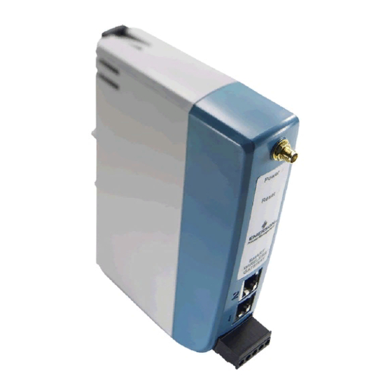
26502044 ler. Figure 1-2 - Gateway Board A CH Breaker Gateway controls up to 48 inputs and 48 The CH Breaker Gateway (Figure 1-2) allows you to digital outputs, and to the CPC controller the board appears drive multiple breakers from a single virtual I/O point by identical to 8RO (relay output) boards and 16AI (input) arranging them into breaker groups. -
Page 8: Power Wiring
80 VA Table 3-1-US and Canada Power Ratings for CPC Transformers Figure 3-1 - Pinout for the 56VA (640-0056) and 80VA (640- Figure 2-2 - Snap-Track Installation 0080) Transformers 2 • CH Breaker Gateway I&O Manual 026-1710 Rev 1 05-15-07... -
Page 9: Networking
0V (SHIELD) to + on PRC100s devices, terminate the network using the three termination jumpers located next to the Gateway MODBUS Connector Figure 4-3 - MODBUS Addressing Switch Positions Connecting the CH Breaker Gateway to the Breaker Panels Networking • 3... -
Page 10: Setting The Net Switches
Gateway board as one or more 16AI Analog Input boards and one or more 8RO boards numbered in succession. Ad- dressing the “boards” represented by the Gateway is achieved using the HHT. 4 • CH Breaker Gateway I&O Manual 026-1710 Rev 1 05-15-07... -
Page 11: Setting The Rs485 I/O Termination Jumpers
Site Controller Soft- ware Setup GATEWAY DIP SWITCH I/O NETWORK OR COM A AND D 5.1. REFLECS BAUD RATE For backwards compatibility with REFLECS, the CH Breaker Gateway behaves on the network identically to 16AI and 8RO boards. These devices should be set up and addressed in the same way I/O boards are set up. -
Page 12: Adding Lighting Schedule Applications
Proofing to Yes. (C8:Proof tab be- comes visible once you cursor across the tabs. See Figure 5-3.) Press (Next Tab) or (Prev Tab) to cursor over to C8:Proof tab. 6 • CH Breaker Gateway I&O Manual 026-1710 Rev 1 05-15-07... -
Page 13: 5.2.3.2. Light Outputs Setup
ON Only, or OFF Only. If any break- er within a group fails the proof, the entire 6.1. CH Breaker Gateway (HHT) group will fail the proof. In the PROOF IN input, enter the virtual Connect the HHT to the Gateway board via the HHT board and point address of the proof input on jack (refer to figure Figure 1-2 #1). -
Page 14: Hht Screens
Figure 6-2 - Starting Board Addresses Screen Next, arrow down to the Option screen. NOTE: If a breaker is assigned to a group that is not set up, a proof failure message will occur. 8 • CH Breaker Gateway I&O Manual 026-1710 Rev 1 05-15-07... -
Page 15: Status
Charts/Appendices 6.1.3. Status From the Option screen, select 1 for Status. The Status screen shows the status of the 48 groups and shows the ON or OFF state of each group and any proof failures (a proof failure is indicated by "*" after the ON or OFF state). Press 7.1. -
Page 16: 8Ro Mapping Table
8RO Board Associated Group Board # Outputs Number 8 Outputs 8 Outputs 9-16 8 Outputs 17-24 8 Outputs 25-32 8 Outputs 33-40 8 Outputs 41-48 Table 7-2 - 8RO Mapping 10 • CH Breaker Gateway I&O Manual 026-1710 Rev 1 05-15-07... -
Page 17: Appendix A: Worksheets
Appendix A: Worksheets Use the workspace below to assign breakers to groups. Refer to Table A-2 for group number board and point assign- ment. Panel 1 Breakers Panel 2 Breakers Panel 3 Breakers Panel 4 Breakers Group# Group# Group# Group# Group# Group# Group#... - Page 18 16AI Address = ____ Fill in the Gateway 16AI board address that you set with the HHT. For groups 17-32, add 1; for groups 33-48, add 2. 8RO Address = ____Fill in the Gateway 8RO board address that you set with the HHT for Groups 1-8. For Groups 9-16, add 1;...
- Page 19 Table A-2 - Mapping Group Numbers to Point Numbers...
-
Page 20: Appendix B: Troubleshooting
Appendix B: Troubleshooting SYMPTOM POSSIBLE PROBLEM SOLUTION Board Offline I/O Network Problems Check wiring polarity. Verify the 485+ uses one color and the 485- uses the other color throughout the network. Check each connector for any loose wires or frayed strands between connectors. - Page 21 SYMPTOM POSSIBLE PROBLEM SOLUTION HHT Home screen displays Communication has been lost Check I/O Net wiring. FAIL: I/O NET. between the site controller and the Gateway. Check that 16AI and 8RO Red Alarm Status LED is blink- addresses are set with the HHT, ing once per second.
Need help?
Do you have a question about the CH Breaker Gateway and is the answer not in the manual?
Questions and answers