Emerson Smart Wireless Gateway Reference Manual
Hide thumbs
Also See for Smart Wireless Gateway:
- Reference manual (92 pages) ,
- Quick start manual (24 pages)
Table of Contents
Advertisement
Quick Links
Advertisement
Table of Contents

Related Manuals for Emerson Smart Wireless Gateway


Summary of Contents for Emerson Smart Wireless Gateway
- Page 1 Reference Manual 00809-0200-4420, Rev EA November 2011 Smart Wireless Gateway...
- Page 3 For information on Rosemount nuclear-qualified products, contact your local Emerson Process Management Sales Representative. PlantWeb is a registered trademark of one of the Emerson Process Management group of companies. Modbus is a registered trademark of Schneider Automation, Inc.
-
Page 5: Table Of Contents
Reference Manual 00809-0200-4420, Rev EA Smart Wireless Gateway November 2011 Table of Contents Safety Messages ..........1-1 SECTION 1 Introduction . - Page 6 Reference Manual 00809-0200-4420, Rev EA Smart Wireless Gateway November 2011 SECTION 6 Troubleshooting SECTION 7 Glossary Functional Specifications ........A-1 APPENDIX A Physical Specifications .
-
Page 7: Safety Messages
The Smart Wireless Gateway provides industry leading security, scalability, and data reliability. Layered security ensures that the network stays protected. Additional devices can be added at anytime. There is no need to configure communication paths because the Gateway manages the network automatically. -
Page 8: Manual
Section 4 – Software Setup This section describes the installation and setup of the optional software included with the Smart Wireless Gateway. This software will aid in secure host integration as well as wireless field device configuration. Section 5 – Host Integration This section describes how to connect the Gateway to a host system and integrate data gathered from the field device network. -
Page 9: Service Support
RETURN OF MATERIALS Emerson Process Management representative. Within the United States, call the Emerson Process Management Response Center toll-free number 1 800 654 7768. The center, which is available 24 hours a day, will assist you with any needed information or materials. - Page 10 Reference Manual 00809-0200-4420, Rev EA Smart Wireless Gateway November 2011...
-
Page 11: Overview
Reference Manual 00809-0200-4420, Rev EA Smart Wireless Gateway November 2011 Section 2 Initial Connection Overview ........page 2-1 System Requirements . -
Page 12: System Requirements
Reference Manual 00809-0200-4420, Rev EA Smart Wireless Gateway November 2011 The following requirements apply to the PC/Laptop used to configure the SYSTEM Gateway. Additional requirements may apply if using the optional Security REQUIREMENTS ® Setup Utility or AMS Wireless Configurator. See Section 4: Software Setup on page 4-1 for more information. -
Page 13: Connections And Power
Reference Manual 00809-0200-4420, Rev EA Smart Wireless Gateway November 2011 Table 2-1. Default IP Addresses Gateway PC/Laptop Ethernet 1 192.168.1.12 192.168.1.10 Ethernet 2 192.168.2.12 192.168.2.10 Ethernet 1 (DeltaV Ready) 10.5.255.254 10.5.255.200 Ethernet 2 (DeltaV Ready) 10.9.255.254 10.9.255.200 Physically connect the PC/Laptop to the Gateway with the supplied crossover... -
Page 14: Configure The Gateway
Each of the initial passwords for the user accounts is default. It is recommended, for security purposes, that these passwords are changed. The administrator password should be appropriately noted when changed. If it is lost, please contact Emerson Process Management for technical support. - Page 15 Reference Manual 00809-0200-4420, Rev EA Smart Wireless Gateway November 2011 To change the User Accounts Passwords: Navigate to Setup>Security>User accounts. Set the new password for each role based user account, and confirm. Click Submit. Figure 2-2. User Accounts Time Settings The Gateway is the timekeeper for the WirelessHART network, so it is imperative that the Gateway’s time is accurate for timestamp data to be...
- Page 16 Reference Manual 00809-0200-4420, Rev EA Smart Wireless Gateway November 2011 Figure 2-3. Time Settings TCP/IP Network Settings Use caution when making changes to the TCP/IP network settings. If they are lost or improperly configured, it may be impossible to log into the Gateway. Contact the network administrator for information on the proper TCP/IP network settings to apply.
- Page 17 Reference Manual 00809-0200-4420, Rev EA Smart Wireless Gateway November 2011 To change the TCP/IP Network Settings: Navigate to Setup>Ethernet protocol. Select Specify an IP address (recommended). Enter the following: • Hostname • Domain Name • IP Address • Netmask • Gateway Click Submit.
-
Page 18: System Backup
Reference Manual 00809-0200-4420, Rev EA Smart Wireless Gateway November 2011 The Gateway has a System Backup and Restore feature that saves all System Backup user-configured data. It is best practice that a System Backup be performed periodically throughout the installation and configuration process. -
Page 19: Overview
This section also describes how to mount the optional remote antenna. General Considerations The Smart Wireless Gateway may be mounted in any General Purpose location. Be sure the covers are secured tightly to prevent exposure of any electronics to moisture and contamination. -
Page 20: Physical Description
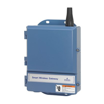
Reference Manual 00809-0200-4420, Rev EA Smart Wireless Gateway November 2011 For dimensional drawing information refer to Appendix A: Product Physical Description Specifications. The cast aluminum housing encloses the electronics circuitry of the Gateway. The front of the enclosure has an upper cover and a junction box cover. -
Page 21: Bracket Mount (Alternate)
Reference Manual 00809-0200-4420, Rev EA Smart Wireless Gateway November 2011 Figure 3-2. Pipe Mount The following hardware and tools are needed to mount the Gateway to a Bracket Mount (alternate) support bracket: • Four -in. bolts • Mounting support bracket •... -
Page 22: Remote Antenna (Optional)
To maintain wireless performance and avoid non-compliance with spectrum regulations, do not change the length of cable or the antenna type. If the supplied remote mount antenna kit is not installed per these instructions, Emerson Process Management is not responsible for wireless performance or non-compliance with spectrum regulations. - Page 23 Reference Manual 00809-0200-4420, Rev EA Smart Wireless Gateway November 2011 Figure 3-3. Installation of WL2/WN2 Option Installation of WL3/WL4 Option (indoor to outdoor applications): Mount the antenna on a 1.5-2 inch pipe mast using the supplied mounting equipment. Mount the lightning arrestor near the building egress.
-
Page 24: Connecting
Reference Manual 00809-0200-4420, Rev EA Smart Wireless Gateway November 2011 NOTE: WEATHER PROOFING IS REQUIRED! The remote mount antenna kit includes coaxial sealant for the cable connections for the lightning arrestor, antenna, and Gateway. The coaxial sealant must be applied to guarantee performance of the wireless field network. -
Page 25: Ethernet
Reference Manual 00809-0200-4420, Rev EA Smart Wireless Gateway November 2011 The Gateway is equipped with two 10/100 Based-TX Ethernet Ethernet communications ports (see Figure 3-6). These connections can be used to access the Gateway’s web interface and to communicate Modbus TCP and OPC protocols. -
Page 26: Terminating Resistors
Reference Manual 00809-0200-4420, Rev EA Smart Wireless Gateway November 2011 Three DIP switches are provided to enable various terminating resistors to the Terminating Resistors RS-485 data bus. The switches are found inside the electronics housing near the top center of the main circuit board (Figure 3-8). -
Page 27: Power
Reference Manual 00809-0200-4420, Rev EA Smart Wireless Gateway November 2011 The Gateway is designed to be powered by 24 VDC (nominal) and requires Power 250 mA of current. The positive and negative connections are found on the left side of the terminal block (Figure 3-6). An additional case ground is found on the left side of the junction box enclosure. - Page 28 Reference Manual 00809-0200-4420, Rev EA Smart Wireless Gateway November 2011 3-10...
-
Page 29: Overview
This section discusses the installation and setup of the optional software OVERVIEW included with the Smart Wireless Gateway. This software is not required for the wireless field network to operate; however, it will aid in secure host integration as well as wireless field device configuration. The following table describes what items are installed and on which disk they can be found. -
Page 30: Software Installation
Reference Manual 00809-0200-4420, Rev EA Smart Wireless Gateway November 2011 Table 4-3. Supported Operating Systems Operating System Version Windows XP Professional, Service Pack 3 Windows Server 2003 Standard, Service Pack 2 Windows Server 2003 R2 Standard, Service Pack 2 Windows Server 2008... -
Page 31: Setup
Reference Manual 00809-0200-4420, Rev EA Smart Wireless Gateway November 2011 Figure 4-1. Typical Host System Architecture Using Security Setup NOTE: OPC communications requires the use of the Security Setup Utility regardless of whether encryption is required. Setup In the Security Setup Utility add a new proxy for each Gateway based on the communication protocol that is being used. -
Page 32: Ams Wireless Configurator
Reference Manual 00809-0200-4420, Rev EA Smart Wireless Gateway November 2011 During this process the Gateway will exchange security certificates (digital signatures) with the proxy. Figure 4-2. Security Setup Utility AMS Wireless Configurator helps deploy and configure wireless field devices. AMS WIRELESS... - Page 33 Reference Manual 00809-0200-4420, Rev EA Smart Wireless Gateway November 2011 Use the following procedure to configure a wireless network for AMS Wireless Configurator: 1. Open the Network Configuration application. 2. Click Add… 3. Select Wireless Network and click Install… 4. Click Next.
-
Page 34: Licensing And Credits
Reference Manual 00809-0200-4420, Rev EA Smart Wireless Gateway November 2011 The latest licensing agreements are included on each disk of the software LICENSING AND pack. CREDITS “This product includes software developed by the OpenSSL Project for use in the OpenSSL Toolkit. (http://www.openssl.org/)”... -
Page 35: Overview
Reference Manual 00809-0200-4420, Rev EA Smart Wireless Gateway November 2011 Section 5 Host Integration Overview ........page 5-1 Network Architecture . - Page 36 Reference Manual 00809-0200-4420, Rev EA Smart Wireless Gateway November 2011 Fiber Optic (Optional) A Fiber Optic connection supports Modbus TCP, OPC, AMS, and HART TCP protocols. Using this connection type, the Gateway is wired to a fiber optic switch (see Figure 5-2).
-
Page 37: Internal Firewall
Reference Manual 00809-0200-4420, Rev EA Smart Wireless Gateway November 2011 Figure 5-3. RS485 Architecture INTERNAL FIREWALL The Gateway supports an internal firewall that inspects both incoming and outgoing data packets. TCP ports for communication protocols are user configurable, including user specified port numbers and the ability to disable ports. -
Page 38: Modbus
Reference Manual 00809-0200-4420, Rev EA Smart Wireless Gateway November 2011 The Gateway supports both Modbus RTU over the RS-485 serial port and MODBUS Modbus TCP over Ethernet. It functions as a sub device on the Modbus network and must be polled by a Modbus master or client (host system). -
Page 39: Register Mapping
Reference Manual 00809-0200-4420, Rev EA Smart Wireless Gateway November 2011 Floating point representation: This setting determines if the Gateway uses floating point values or integer values. There are three options for this setting. • Float: This option uses 32 bit floating point values. - Page 40 Reference Manual 00809-0200-4420, Rev EA Smart Wireless Gateway November 2011 Figure 5-6. Modbus Register Map Page To add a new data point to the Modbus register map: 1. Click New entry. 2. Complete all of the table entries for the new data point (note that the entry columns may vary based on the Modbus communications settings).
- Page 41 Reference Manual 00809-0200-4420, Rev EA Smart Wireless Gateway November 2011 Table 5-1. Device parameters available via Modbus Parameter Description Data Type Primary Variable 32 bit float Secondary Variable 32 bit float Tertiary Variable 32 bit float Quaternary Variable 32 bit float...
- Page 42 Reference Manual 00809-0200-4420, Rev EA Smart Wireless Gateway November 2011 Table 5-2. Predefined Modbus Registers Description Register Data Type Current Year (1) 49001 32 bit int Current Month (1) 49002 32 bit int Current Day (1) 49003 32 bit int...
-
Page 43: Troubleshooting
Reference Manual 00809-0200-4420, Rev EA Smart Wireless Gateway November 2011 Section 6 Troubleshooting This section provides basic troubleshooting tips for the Smart Wireless Field Network. To receive technical support by phone: Global Service Center Software and Integration support. • United States – 1 800 833 8314 •... - Page 44 Reference Manual 00809-0200-4420, Rev EA Smart Wireless Gateway November 2011 AMS Wireless Configurator Gateway does not appear in AMS Wireless 1. Verify the Security Setup Utility is installed on the same PC as AMS Wireless Configurator. Configurator 2. Setup a wireless network interface using the Network Configuration application. See Section 4: Software Setup.
- Page 45 Reference Manual 00809-0200-4420, Rev EA Smart Wireless Gateway November 2011 OPC Communications OPC application can not find a Gateway 1. Verify the Security Setup Utility has been installed on the same PC as the OPC application. OPC server 2. Configure an OPC proxy for the Gateway. See Section 4: Software Setup.
- Page 46 Reference Manual 00809-0200-4420, Rev EA Smart Wireless Gateway November 2011...
- Page 47 November 2011 Section 7 Glossary This glossary defines terms used throughout this manual or that appear in the web interface of the Smart Wireless Gateway. Term Definition Access Control List A list of all devices that are approved to join the network.
- Page 48 Primary Interface Ethernet 1 or Fiber Optic port that is used for primary host communications. Private Network/LAN A local connection between a Smart Wireless Gateway and a PC/Laptop. This network is used for commissioning and configuration of the Gateway. Reliability A measure of connectivity between the Gateway and a wireless field device.
-
Page 49: Functional Specifications
Reference Manual 00809-0200-4420, Rev EA Smart Wireless Gateway November 2011 Appendix A Product Specifications Functional Specifications ......page A-1 Physical Specifications . -
Page 50: Physical Specifications
Reference Manual 00809-0200-4420, Rev EA Smart Wireless Gateway November 2011 PHYSICAL Weight 10 lb. (4,54 kg) SPECIFICATIONS Material of Construction Housing Low-copper aluminum, NEMA 4X Paint Polyurethane Cover Gasket Silicone Rubber Antenna Integrated Antenna: PBT/PC Remote Antenna: Fiber Glass Certifications Class I Division 2 (U.S.) -
Page 51: System Security Specifications
Ethernet Secure Sockets Layer (SSL) enabled (default) TCP/IP communications SPECIFICATIONS Smart Wireless Gateway Access Role-based Access Control (RBAC) including Administrator, Maintenance, Operator, and Executive. Administrator has complete control of the Gateway and connections to host systems and the self-organizing network. -
Page 52: Dimensional Drawings
Reference Manual 00809-0200-4420, Rev EA Smart Wireless Gateway November 2011 DIMENSIONAL DRAWINGS Figure A-1. Smart Wireless Gateway (Dimensions are in inches (millimeters)) 9.02 3.51 (229) 2.93 (89) 2.525 (74,42) (64,14) 2.81 (71,4) 12.03 (306) 11.15 (283) Lower Cover Remove for... - Page 53 The Remote Omni-Antenna kit includes sealant tape for remote antenna connection, as well as mounting brackets for the antenna, Lightning Arrestor, and the Smart Wireless Gateway. Lightning protection is included on all the options. WL3 and WL4 provide lightning protection along with the ability to have the gateway mounted indoors, the antenna mounted outdoors, and the lightning arrestor mounted at the building egress.
-
Page 54: Ordering Information
November 2011 ORDERING INFORMATION Table A-1. Smart Wireless Gateway Ordering Information ★ The Standard offering represents the most common options. The starred options (★) should be selected for best delivery. __The Expanded offering is subject to additional delivery lead time. -
Page 55: Accessories And Spare Parts
Smart Wireless Gateway November 2011 Table A-1. Smart Wireless Gateway Ordering Information ★ The Standard offering represents the most common options. The starred options (★) should be selected for best delivery. __The Expanded offering is subject to additional delivery lead time. - Page 56 Reference Manual 00809-0200-4420, Rev EA Smart Wireless Gateway November 2011...
-
Page 57: Approved Manufacturing Locations
RF spectrum. Nearly every country COMPLIANCE requires this type of product certification. Emerson is working with governmental agencies around the world to supply fully compliant products and remove the risk of violating country directives or laws governing wireless device usage. -
Page 58: European Union Directive Information
INFORMATION ATEX Directive (94/9/EC) Emerson Process Management complies with the ATEX Directive. Electro Magnetic Compatibility (EMC) (2004/108/EC) Emerson Process Management complies with the EMC Directive. Radio and Telecommunications Terminal Equipment Directive (R&TTE)(1999/5/EC) -
Page 59: Overview
Setup ......... . page C-2 Native integration with DeltaV enables the Smart Wireless Gateway to be... -
Page 60: Setup
Controller and I/O Smart Wireless Gateway SETUP Out of the box the Smart Wireless Gateway is pre-configured for use on the DeltaV control network. In the DeltaV Explore application, the Gateway will automatically appear in the Decommissioned Nodes folder. To setup a wireless network will require 3 steps: 1. - Page 61 EXPLORE to launch the DeltaV Explorer application. 2. Expand the folder SYSTEM CONFIGURATION >PHYSICAL NETWORK>DECOMMISSIONED NODES. 3. Right click on the Smart Wireless Gateway and select Commission. 4. Enter a name for the Gateway and click OK. 5. Click YES when prompted to Auto-Sense Wireless Gateway.
- Page 62 Reference Manual 00809-0200-4420, Rev EA Smart Wireless Gateway November 2011 Figure C-4. Gateway context menu (right click). Now the Gateway and wireless devices are fully commissioned and available to use in other DeltaV applications. When new devices are added to the wireless network, they will need to be assigned to DeltaV channels through the reconcile process (right click on Gateway and select configure IO).
-
Page 63: Overview
Gateway Replacement ......page D-7 Redundancy for the Smart Wireless Gateway increases the availability of the... - Page 64 Reference Manual 00809-0200-4420, Rev EA Smart Wireless Gateway November 2011 The user specified names are for identification purposes. These names will be used in diagnostic messages and host system integration to help identify each Gateway. It is recommended that these names be marked on each physical Gateway, in addition to the configuration settings.
-
Page 65: Mounting And Connections
Reference Manual 00809-0200-4420, Rev EA Smart Wireless Gateway November 2011 Figure D-2. Redundancy Setup Connections Gateway B Gateway A PC / Laptop Secondary Ethernet Primary Ethernet Once the Gateways have finished the pairing process, Gateway A will appear as the current active Gateway on the left hand side and Gateway B will be the standby Gateway on the right (note that left/right hand appearance can be changed on the Redundancy System Settings page). - Page 66 Reference Manual 00809-0200-4420, Rev EA Smart Wireless Gateway November 2011 Figure D-3. Ethernet Connection Architecture Engineering Station Process Control Network Gateway A Gateway B Primary Ethernet Primary Ethernet Secondary Ethernet NOTE: The primary Ethernet port for each Gateway should be connected to separate network switches on the same process control network.
- Page 67 Reference Manual 00809-0200-4420, Rev EA Smart Wireless Gateway November 2011 NOTE: In either a simplex or dual RS-485 architecture, the primary Ethernet ports can be connected to an asset management network to provide connectivity to AMS Device Manager or AMS Wireless Configurator.
-
Page 68: Diagnostics
Reference Manual 00809-0200-4420, Rev EA Smart Wireless Gateway November 2011 The redundant system will perform many diagnostic checks to verify the DIAGNOSTICS health and connectivity of the system. This diagnostics information can be found by navigating to Diagnostics>Advanced>Redundancy Status. Figure D-6. Redundancy Status These diagnostics can also be mapped to Modbus registers or OPC tags. -
Page 69: Gateway Replacement
Reference Manual 00809-0200-4420, Rev EA Smart Wireless Gateway November 2011 In addition to the redundancy diagnostics, an additional check may be configured to test network connectivity to a host system or other application. The redundant system will use this check to determine the best connectivity option and which Gateway should be set to the active Gateway. - Page 70 Reference Manual 00809-0200-4420, Rev EA Smart Wireless Gateway November 2011...
- Page 72 The Emerson logo is a trade mark and service mark of Emerson Electric Co. Rosemount and the Rosemount logotype are registered trademarks of Rosemount Inc. PlantWeb is a registered trademark of one of the Emerson Process Management group of companies. HART is a registered trademark of the HART Communication Foundation.
Need help?
Do you have a question about the Smart Wireless Gateway and is the answer not in the manual?
Questions and answers