Advertisement
BBQ Grillware ® is a registered trademark
of LF, LLC. All Rights Reserved.
MH45812
3JYP
Questions, problems, missing parts?
service department at 1-866-869-5300, 8 a.m.-6 p.m., EST, Monday-Friday.
®
Before returning to your retailer, call our customer
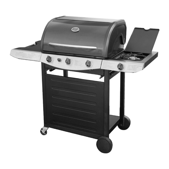
ITEM # 196124
3-Burner LP Gas Grill
MODEL # GGPL-2100
version 2.0
Advertisement
Table of Contents

Related Manuals for BBQ GGPL-2100


Summary of Contents for BBQ GGPL-2100
- Page 1 ITEM # 196124 3-Burner LP Gas Grill ® MODEL # GGPL-2100 BBQ Grillware ® is a registered trademark of LF, LLC. All Rights Reserved. MH45812 3JYP version 2.0 Questions, problems, missing parts? Before returning to your retailer, call our customer...
- Page 2 DANGER If you smell gas: 1. Shut off gas to the appliance. 2. Extinguish any open flame. 3. Open Lid. 4. If odor continues, keep away from the appliance and immediately call your gas supplier or your fire department. WARNING 1.
-
Page 3: Table Of Contents
TABLE OF CONTENTS Safety Information ........................Package Contents ........................Illustrated Parts List ........................Hardware Contents ........................Preparation ..........................Assembly Instructions ........................ Operation Instructions ....................... Care and Maintenance ......................Troubleshooting ......................... Warranty ............................ Replacement Parts List ...................... -
Page 4: Safety Information
SAFETY INFORMATION Please read and understand this entire manual before attempting to assemble, operate or install the product. If you have any questions regarding the product, please call customer service at 1-866-869-5300, 8 a.m.-6 p.m., EST, Monday-Friday. 1. DO NOT store or use gasoline or any other flammable vapors and liquids within 25 feet (8m) of this or any other appliance. - Page 5 20. This grill is for outside use only, and should not be used in a building, garage, under overhangs or any other enclosed area. 21. The use of alcohol, prescription or non-prescription drugs may impair the operator's ability to properly assemble or safely operate the grill. 22.
-
Page 6: Package Contents
PACKAGE CONTENTS Description Quantity Description Quantity Part Part Left side frame Heat shield Right side frame Cooking grid Base panel Warming rack Front cart panel Knob bezel Knob Caster Side burner rack Wheel assembly Right side table AA battery Left side table Grill housing assembly Drip pan Grease collector... -
Page 7: Illustrated Parts List
ILLUSTRATED PARTS LIST Left side frame Right side frame Base panel Caster Front cart panel Wheel assembly Right side table Left side table Grill housing assembly Drip pan Grease Collector Right side control panel Heat shield Cooking grid Warming rack... - Page 8 ILLUSTRATED PARTS LIST Knob bezel Knob Side burner rack AA battery...
-
Page 9: Hardware Contents
HARDWARE CONTENTS Description Description Quantity Part Quantity Part Picture Picture M6x12 Washer Screw M4x10 Lock Screw Washer Wrench R-Pin C-Clip PREPARATION Before beginning assembly of product, make sure all parts are present. Compare parts with package contents list and diagram above. If any part is missing or damaged, do not attempt to assemble the product. -
Page 10: Assembly Instructions
ASSEMBLY INSTRUCTIONS Step 1: Attach left side frame (A) and right side frame (B) to the front cart panel (D) using four M6x12mm screws (BB). Hardware Used M6x12 Screw Step 2: Install the base panel (C) into the cart assembly using four lock washers (HH) and four M6x12mm screws (BB). - Page 11 ASSEMBLY INSTRUCTIONS Step 3: Insert the caster wheel assemblies (E) into the left side frame (A) using wrench (FF) provided. Step 4: Install the wheel assemblies (F) on the right side frame (B) using two R-pins (DD) as shown. Hardware Used R-Pin Step 5: 1) Place the left side table (H) and the right side table (G) at the top of the cart assembly...
- Page 12 ASSEMBLY INSTRUCTIONS 3) Install the grill housing assembly using six washers (GG), lock washers (HH), and M6x12mm screws (BB) as shown. First insert the back screws in an alternating pattern (install one screw on the left then install the next screw on the right side). NOTE: DO NOT TIGHTEN SCREWS UNTIL ALL FASTENERS ARE INSTALLED 4) Install the left side control panel with the grill housing assembly control panel using one M4x10mm screw (CC) as shown.
- Page 13 ASSEMBLY INSTRUCTIONS Step 6: 1) Install the electrode wire to the side burner valve by plugging the end of the wire into the socket as shown. Install the knob bezel (P) onto the right side control panel (L) and side burner value using two M4x10mm screws (CC), making sure to keep the side with the red line of the knob bezel upward as shown.
- Page 14 ASSEMBLY INSTRUCTIONS Install the right side control panel on right side table using two M6x12mm screws (BB) as shown. 5) Connect the side burner mixing tube with the C-clip (EE). Hardware Used M6x12 Screw M4x10 Screw C-Clip...
- Page 15 ASSEMBLY INSTRUCTIONS Step 7: Install the knob (Q) on the right side table assembly as shown. Step 8: Open the lid and put three heat shields (M) into the grill housing. Place two cooking grates (N) in the grill housing. Install the warming rack (O) on the top of the grill housing. Install the side burner rack (R) as shown.
- Page 16 ASSEMBLY INSTRUCTIONS Step 9: Install the drip pan (J) under the grill housing at the back side. Install the grease collection pan (K) under the drip pan as shown. Step 10: To install battery, open the ignitor by turning counterclockwise until the ignitor button detaches itself.
-
Page 17: Operation Instructions
OPERATION INSTRUCTIONS CAUTION: Only use the regulator provided! If a replacement is necessary, please call our customer service center. Do not use replacement parts that are not intended for this grill. Connecting gas cylinder: The propane gas supply cylinder to be used must be constructed and marked in accordance with the Specifications for Propane Gas Cylinders of the U.S. - Page 18 OPERATION INSTRUCTIONS Connecting the Gas Cylinder Always place the propane cylinder on the tank brackets located on the right side of the cart. Always confirm that all burner control knobs are in the OFF position before activating the gas supply. Before connection, be sure that there is no debris caught in the head of the gas cylinder, head of the regulator valve, or in the head of the burner and burner ports.
- Page 19 OPERATION INSTRUCTIONS Lighting Your Grill DANGER: Failure to open lid while igniting the grill or not waiting 5 minutes to allow the gas to clear if the grill does not light may result in an explosive flare-up which can cause serious bodily injury or death.
- Page 20 OPERATION INSTRUCTIONS Lighting Burner With A Match: 1. Place a match in the end of the match holder that is pre-installed on the side of Grill Housing. Once lit, immediately place the flame through the hole as shown near the burner ports. 2.
-
Page 21: Care And Maintenance
CARE AND MAINTANCE Cooking Grids - The porcelain grates have a glass-like composition that should be handled with care not to chip. Use mild dishwashing detergent or baking soda and hot water solution. Non abrasive scouring powder can be used on stubborn stains, and then rinse with water. Heat Shield - Clean residue with wire brush and wash with soapy water. -
Page 22: Troubleshooting
TROUBLESHOOTING Please refer to the following Troubleshooting Guide if you have any problems lighting or operating your grill Many solutions given here can make your grilling experience safer and more enjoyable... - Page 23 TROUBLESHOOTING Problem Possible Solutions The propane regulator assembly incorporates an excess flow device designed to supply the grill with sufficient gas flow under normal conditions, yet control excess gas flow. Rapid changes in pressure can trigger the excess flow device, providing a low flame and low temperature.If the tank valve is turned open to allow gas flow while a burner valve is open, the surge of pressure will cause the device to activate.
- Page 24 TROUBLESHOOTING Problem Possible Solutions 1. Push and turn the knob and check for sparks. 2. If there is a spark, check to make sure gas is supplied to the burner. a. Purge the line of any trapped air. Grill will not light b.
-
Page 25: Warranty
WARRANTY Proof of purchase is required to access this warranty program, which is in effect from date of purchase. If customer is unable to provide proof of purchase, or after the warranty has expired, customers will be subject to parts, shipping and handling fees. Full 30-Day Warranty For 30 days from the date of purchase, any missing and damaged parts will be replaced at no charge, with a valid proof of purchase. -
Page 26: Replacement Parts List
REPLACEMENT PARTS LIST Part# Description CG2150-37R Side frame (left) CG2150-38R Side frame (right) Base panel CG2150-20A CG2150-19A Cart panel (front) 12GA5-07-B-2 Caster wheel assembly Wheel assembly 12GA5-07-B-1 31GA5-12-R-4359-1-R Right side table with burner Left side table with accessory hook 31GA5-12-L-4359-1-R 31GA5-27-1 Drip pan 31GA5-11-1-R...
Need help?
Do you have a question about the GGPL-2100 and is the answer not in the manual?
Questions and answers