Table of Contents
Advertisement
Quick Links
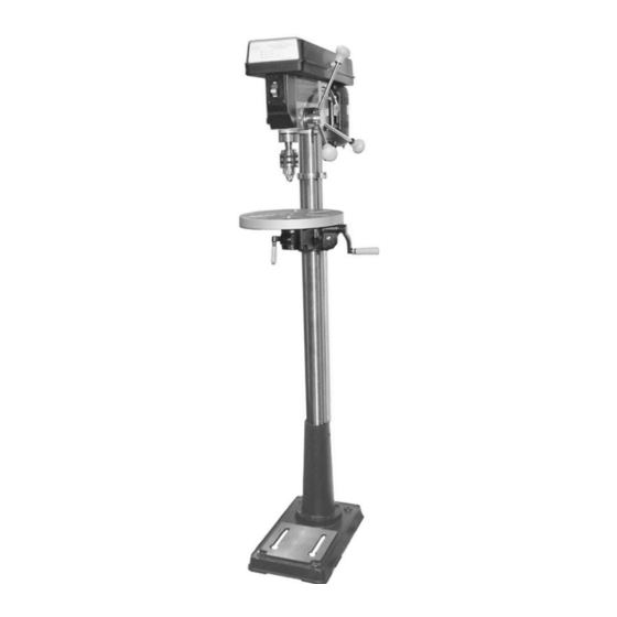
16 SPEED FLOOR DRILL PRESS
SEt uP AnD OPERAtIng InStRuctIOnS
Diagrams within this manual may not be drawn proportionally.
Due to continuing improvements, actual product may differ slightly from the product described herein.
Distributed exclusively by Harbor Freight tools
Visit our website at: http://www.harborfreight.com
Read this material before using this product.
Failure to do so can result in serious injury.
SAVE tHIS MAnuAL.
Copyright
2000 by Harbor Freight Tools
©
or any artwork contained herein may be reproduced in any shape or form without the
express written consent of Harbor Freight Tools.
For technical questions or replacement parts, please call 1-800-444-3353.
Model
3491 Mission Oaks Blvd., Camarillo, CA 93011
43378
. All rights reserved. No portion of this manual
®
.
®
cover revised 07i
Advertisement
Table of Contents

Related Manuals for Central Machinery 43378


Summary of Contents for Central Machinery 43378
-
Page 1: Set Up And Operating Instructions
. All rights reserved. No portion of this manual © ® or any artwork contained herein may be reproduced in any shape or form without the express written consent of Harbor Freight Tools. For technical questions or replacement parts, please call 1-800-444-3353. cover revised 07i... -
Page 2: Specifications
Do not force tool. It will do the job better and more safely at the rate for which it was intended. Do not use inappropriate attachments in an attempt to exceed the tool capacity. use the right tool for the job. Do not attempt to force a small tool or attachment to REV 00j SKU 43378 Page 2... - Page 3 18. Replacement parts and accessories. When servicing, use only identical replacement parts. Use of any other parts will void the warranty. Only use accessories intended for use with this tool. Approved accessories are available from Harbor Freight Tools. SKU 43378 Page 3...
- Page 4 It must be under- stood by the operator that common sense and caution are factors which cannot be built into this product, but must be supplied by the operator. Rev 07i SKU 43378 Page 4...
-
Page 5: Vibration Hazard
Turn the motor OFF, and wait until it stops spinning before attempting to remove it. Avoid being caught and pulled into the spinning chuck. Do not wear gloves, long sleeve shirts, ties, or jewelry. Long hair must be bundled behind the head. Rev 07i SKU 43378 Page 5... - Page 6 - Bag of Loose Parts - Box of Loose Parts Column Support (B4) Base (B6) If any parts are missing or broken, please call Harbor Freight Tools at the number on the cover of this manual as soon as possible. Rev 07i SKU 43378...
- Page 7 With the Table in place, retighten the Table Clamp. cAutIOn: Avoid injuries. the next step involves lifting the Head Assembly onto the column tube. the Head Assembly weighs about 55 lb. Have someone help you lift this assembly into place. Rev 07i SKU 43378 Page 7...
- Page 8 Speed-Belt Chart Motor Pulley (11) Pulley Cover (A23) Spindle Pulley (A3) V-belt (A1) Set Screw (12) V-belt (A1) Adjust the height of the Motor Pulley. - Lay a straight edge across the two pulleys. Rev 07i SKU 43378 Page 8...
- Page 9 Lock Screw (B12) Screw (B12) with a Hex Wrench. Set Screw (B11) Set Screw (B11) - Rotate the Table until it is square to the bit. - Retighten the Lock Screw, then the Set Screw. Rev 07i SKU 43378 Page 9...
-
Page 10: Operation
Keep the Switch Key in a safe place. Setting the Depth Scale to Drill to a Specified Depth During this procedure, refer to the photo on page 9. Secure the workpiece to the Table. Rev 07i SKU 43378 Page 10... -
Page 11: Tilting The Table
Loosen Set Screw (B11) under the Arm assembly with the Allen wrench. Loosen the Lock Screw (B12) with the Hex Wrench. Rotate the Table to the desired angle. The scale can be used to approximate the angle. Retighten the Lock Screw, then the Set Screw. Rev 07i SKU 43378 Page 11... -
Page 12: Maintenance
This will prevent the Chuck and Arbor assembly from dropping during Quill Spring adjustment. Insert a screwdriver in the lower-front notch of the Quill Spring Cap (39). Hold it in place and, using a wrench, remove the (outer) Hex Nut (38) only. Rev 07i SKU 43378 Page 12... -
Page 13: General Maintenance
Head assemblies. Check belts for wear and replace if frayed or damaged in any way. Lubricate Spindle assembly with a light oil, weekly. Periodically, grease the rack. Store in a clean and dry location. Rev 07i SKU 43378 Page 13... -
Page 14: Troubleshooting
TECHNICIANS AND NOT BY THE BUYER. THE BUYER ASSUMES ALL RISK AND LIABILITY ARISING OUT OF HIS OR HER REPAIRS TO THE ORIGINAL PRODUCT OR REPLACEMENT PARTS THERETO, OR ARIS- ING OUT OF HIS OR HER INSTALLATION OF REPLACEMENT PARTS THERETO. Rev 07i SKU 43378 Page 14... -
Page 15: Head Assembly Parts List
Set Screw, Head Lock, M8x25 Allen Wrench, 4mm Depth Lock Screw Allen Wrench, 3mm Knob nOtE: Some parts are listed in these Part Lists are shown for illustration purposes only and are not available individually as replacement parts. Rev 07i SKU 43378 Page 15... - Page 16 Head Assembly Drawing SKU 43378 Page 16...
- Page 17 Ball Bearing Quill Gasket Quill Ball Bearing Spindle Shaft Arbor Chuck Chuck Key Wedge Drift Key Ball Bearing Idler Pulley Idler Pivot Knob Pan Head Screw, M5x8 Pulley Cover Washer, HD Screw, M16x12 Foam Washer Rev 07i SKU 43378 Page 17...
- Page 18 Pulley and Spindle Assembly Drawing When ordering a part from this drawing, add an “A” prefix to the part number. Rev 07i SKU 43378 Page 18...
- Page 19 Hex Head Screw, M10x40 Base Table Support w/ Indicator Table Crank Gear Pin Set Screw, Socket, M6x10 Bevel Table Lock Screw Table Clamp Arm w/ Scale Table Arm Locking Handle Helical Gear Worm Collar Rev 07i SKU 43378 Page 19...
- Page 20 Assembly Drawing When ordering a part from this drawing, add a “B” prefix to the part number. Rev 07i SKU 43378 Page 20...