Table of Contents
Advertisement
Advertisement
Table of Contents

Related Manuals for Antec ISK 110 VESA


Summary of Contents for Antec ISK 110 VESA
- Page 1 ISK 110 VESA ISK Series ’ ANUAL...
-
Page 2: Table Of Contents
I/O P ONNECTING THE RONT ORTS USB 2.0 Ports...................... 7 AC’97 / HD Audio Ports ..................7 Switch and LED Connectors ................8 Rewiring Motherboard Header Connections ............. 8 ISK 110 VESA OUNTING THE VESA mounting system…………………………………………………………………………………. 9 Stand mounting……………………………………………………………………………………………. 9... - Page 3 ’ ANUAL At Antec, we continually refine and improve our products to ensure the highest quality. It’s possible that your new case will differ slightly from the descriptions in this manual. This isn’t a problem; it’s simply an improvement. As of the date of publication, all features, descriptions, and illustrations in this manual are correct.
-
Page 4: Case Specifications
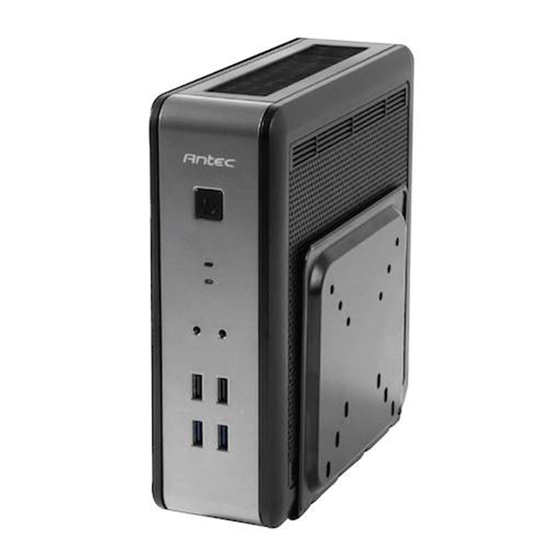
PECIFICATIONS Case Type Mini-ITX Desktop Color Black Dimensions 8.7” (H) x 3.1” (W) x 8.4” (D) 222 mm (H) x 78 mm (W) x 212 mm (D) Net Weight 2.9 lbs / 1.3 kg Drive Bays 2 x 2.5” internal drive bays Motherboard Size Mini-ITX Front I/O Panel... -
Page 5: Power Supply Specifications
OWER UPPLY PECIFICATIONS The ISK 110 VESA is powered by a 90-watt power adapter. Input characteristics: Rated Voltage Input Voltage Range Frequency Range 90 VAC – 264 VAC 100VAC – 240VAC 47 Hz – 63 Hz Output characteristics: Rated Rated... -
Page 6: Hardware Installation Guide
ARDWARE NSTALLATION UIDE 2.1 R EMOVING THE ANEL Lay the case on its right side, with the I/O panel facing you. You will be removing the left panel (the one with the fan) Remove the two screws from the rear of the panel. Using your thumbs, push up on the rear of the panel until the entire Remove these case screws panel pops free from the rest of the chassis. -
Page 7: Internal 2.5" Device Installation
2.3 I 2.5” D NTERNAL EVICE NSTALLATION Note: It is important that you install the insulating sheets in step 3 to ensure that the hard drive(s) and bracket do not come into contact. 2.5” hard drives can be mounted to a bracket underneath the motherboard. -
Page 8: Connecting The Front I/O Ports 3.1 Usb 2.0 Ports
I/O P ONNECTING THE RONT ORTS 3.1 USB 2.0 Connect the front I/O panel USB cables to the USB header pins on your motherboard. Check the motherboard manual to ensure that it matches the table below: Signal Names Signal Names USB Power 1 USB Power 2 Negative Signal 1... -
Page 9: Switch And Led Connectors
3.3 P LED C OWER WITCH RIVE ONNECTORS Connected to your front panel are LED and switch leads for power and HDD LED activity. Attach these to the corresponding connectors on your motherboard. Consult your motherboard user’s manual for specific pin header locations. -
Page 10: Vesa Mounting System
4.1 S TAND MOUNTING Your ISK 110 VESA also comes with a stand so the unit can be installed without use of the VESA mount if needed. 1. Invert the case so that the bottom of the mounting system is facing up. - Page 11 Customer Support: US & Canada 1-800-22ANTEC customersupport@antec.com Europe +31 (0) 10 462-2060 europe.techsupport@antec.com www.antec.com © Copyright 2012 Antec, Inc. All rights reserved. All trademarks are the property of their respective owners. Reproduction in whole or in part without written permission is prohibited.
Need help?
Do you have a question about the ISK 110 VESA and is the answer not in the manual?
Questions and answers