Table of Contents
Advertisement
Quick Links
Advertisement
Table of Contents

Related Manuals for Antec ISK 310-150


Summary of Contents for Antec ISK 310-150
- Page 1 ISK 310-150 ’ ANUAL...
-
Page 2: Table Of Contents
ABLE OF ONTENTS NTRODUCTION Case Specifications.…..………………………………………………………………………………….. 3 Diagram…………………………………………………………………….…………………………………. 3 Power Supply Specifications…………………………………………………………………………. 4 ARDWARE NSTALLATION UIDE Removing the Top Panel.……………………………………………………………………………….5 Removing the Drive Tray Assembly……….……………………………………………………… 5 Motherboard Installation..……………………………………………………………………………. 5 Internal 2.5” Device Installation……………………………………………………………………. 5 External Slim 5.25” Device Installation…………………………………………………………. 6 I/O P ONNECTING THE RONT... - Page 3 ’ ANUAL At Antec, we continually refine and improve our products to ensure the highest quality. It’s possible that your new case will differ slightly from the descriptions in this manual. This isn’t a problem; it’s simply an improvement. As of the date of publication, all features, descriptions, and illustrations in this manual are correct.
-
Page 4: Case Specifications
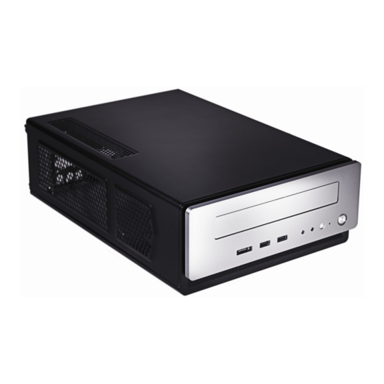
3. Internal 2 x 2.5” HDD bays 4. Half-height expansion slot 5. Motherboard mount – Mini-ITX 6. Front I/O panel 7. FP-150 power supply Note: The ISK 310-150-8 includes a tool bag with Product Overview located inside of the case. -
Page 5: Power Supply Specifications
OWER UPPLY PECIFICATIONS The ISK 310-150 is powered by an FP-150-8 power supply. Input characteristics: Input Voltage Range Frequency Range 100 VAC ~ 240 VAC 47 Hz ~ 63 Hz Output characteristics: DC Output +3.3V +12V -12V +5Vsb Max. Output 0.2A... -
Page 6: Hardware Installation Guide
ARDWARE NSTALLATION UIDE 2.1 R EMOVING THE TOP PANEL Place the case flat on an even, stable surface. Remove the three thumbscrews from the rear of the top panel. Grip the top panel and slide it back several inches until it stops. Grip the panel from the sides and lift it up until it pulls completely free of the main chassis. -
Page 7: Internal 2.5" Device Installation
2.4 I 2.5” D NTERNAL EVICE NSTALLATION Remove the top panel as described in section 2.1. Included at the top of the drive tray assembly is a HDD tray that can support up to two 2.5” devices. On the right side of the drive tray assembly, remove the thumbscrew holding the HDD tray to the rest of the device. -
Page 8: Connecting The Front I/O Ports
You will find a SATA connector on a cable attached to the front ports. This internal SATA connector is designed to connect to a standard SATA connector on your motherboard. This will allow high-speed external hard disk enclosures such as the Antec MX-1 to run at the same speeds as internally installed hard disks. -
Page 9: Switch And Led Connectors
3.4 P LED C OWER WITCH ESET WITCH RIVE ONNECTORS Connected to your front panel are LED and switch leads for power, reset, and HDD LED activity. Attach these to the corresponding connectors on your motherboard. Consult your motherboard user’s manual for specific pin header locations. -
Page 10: Cooling System
OOLING YSTEM ™ E XHAUST There is an 80 x 25mm TriCool™ fan pre-installed on the right-hand side of the case. It has an external, three-speed switch that allows you to choose between quiet performance or maximum cooling. The default speed setting is Low. The fan is mounted so that air blows out of the case. There are externally accessible switches for these fans located at the rear of your case.
Need help?
Do you have a question about the ISK 310-150 and is the answer not in the manual?
Questions and answers