Sign In
Upload
Manuals
Brands
Enterasys Manuals
Network Router
G3G124-24
User Manuals: Enterasys G3G124-24 Network Switch
Manuals and User Guides for Enterasys G3G124-24 Network Switch. We have
3
Enterasys G3G124-24 Network Switch manuals available for free PDF download: Hardware Installation Manual, Quick Reference
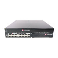
Enterasys G3G124-24 Hardware Installation Manual (70 pages)
G-Series
Brand:
Enterasys
| Category:
Network Router
| Size: 3 MB
Table of Contents
Industry Canada Notice
4
Regulatory Compliance Information
4
Safety Compliance
7
Safety Information
7
Declaration of Conformity
8
Table of Contents
13
About this Guide
17
Who Should Use this Guide
17
How to Use this Guide
17
Related Documents
17
For Information about
17
Document Conventions
18
Commonly Used Acronyms
18
Getting Help
19
Chapter 1: Introduction
21
Overview
21
Features
22
G3G124-24 Switch (Rear View) with 1200 and 400-Watt Power Supplies Installed
22
Poe (Power over Ethernet) Support
24
Fan Management
24
G3G124
24
Chapter 2 : Installation
28
Unpacking the G-Series Switch
28
Shipped with the Switch
28
Required and Shipped Separately
28
Optional Enterasys Components
28
Order of Installation Steps
29
G3G124-24 Optional Poe Module Installation Considerations
29
Mounting the Switch
29
Placing the Switch on a Flat Surface
30
Installing the Switch into a Rack
30
Power Supply Installation Considerations
31
Power Supply Redundancy
31
Attaching the Brackets to the Switch (G3G124-24 with G3G-24TX IOM Shown)
31
Power Distribution According to Number of Installed Power Supplies
32
Allocation of Poe Power to Modules
33
Management of Poe Power to Pds
34
Installing a Power Supply
34
Removing a Power Supply
35
Installing a Power Supply Module (1200-Watt Module into PWR 2 Slot Shown)
35
Installing and Removing an IOM
36
Installing an Optional Poe Module on the G3G-24TX IOM
36
Installing an IOM
37
Installing a Poe Module in the G3G-24TX IOM
37
Installing an IOM (G3G-24TX with Optional Poe Shown)
38
Removing an IOM
39
Connecting Power to the Switch
39
Connecting to the Console Port
40
Connecting to the RJ45 Console Port
40
Console Port Pinout
41
RJ45 to DB9 Adapter Pinout
41
Connecting to the USB Console Port
42
Connecting to the Network
42
Connecting UTP Cables to RJ45 Ports
42
Connecting a UTP Cable Segment to RJ45 Port
43
Four-Wire Crossover Cable RJ45 Pinouts for 10/100BASE-TX
43
Four-Wire Straight-Through Cable RJ45 Pinouts for 10/100BASE-TX
44
Eight-Wire Crossover Cable RJ45 Pinouts for 10/100/1000BASE-TX
44
Installing Optional SFP/XFP
45
Eight-Wire Straight-Through Cable RJ45 Pinouts for 10/100/1000BASE-TX
45
Installing an SFP/XFP (Shown with LC Connector and Without Dust Cover)
46
Removing an XFP/SFP
47
Connecting Fiber-Optic Cables to SFP/XFP Ports
47
Completing the Installation
48
Cable Connection (LC Shown) to Uplink Port with SFP/XFP Installed
48
Installing an Optional Poe Module in the G3G124-24 Switch
49
Removing the Switch Cover
49
Installing the Poe Module
50
Screw and Coverplate Removal for Removing the G3G124-24 Cover
50
Chapter 3: Troubleshooting
51
Checking the Leds
52
System Led
52
G3 System Leds (G3G124-24 Shown)
52
SYSTEM LED Definitions
52
Power Leds
53
IOM Status Leds
53
Fixed and IOM Port Leds
53
Power LED Definitions
53
IOM Status LED Definitions
53
Port LED Definitions
53
Using the Password Reset Button
54
Locating the Password Reset Button
54
Removing the Switch from a Rack
55
Appendix A: Specifications
57
Switch Specifications
57
Regulatory Compliance
57
G3 Switch Specifications
57
Power Supply Specifications
59
IOM Specifications
59
G3G-24TX IOM Specifications
59
G3G-24SFP IOM Specifications
60
G3K-2XFP and G3K-4XFP IOM Specifications
61
Poe Daughter Card Specifications
62
Torque Values
62
G3G-POE Specifications
62
Recommended Torque Values by Screw Size
62
1-Gigabit Ethernet and 100Base-FX Transceiver (SFP) Specifications
63
MGBIC-LC01/MGBIC-MT01 Specifications (1000BASE-SX
63
Mini-GBIC Input/Output Port Specifications
63
MGBIC-LC01/MGBIC-MT01 Optical Specifications
63
MGBIC-LC01/MGBIC-MT01 Operating Range
63
MGBIC-02 Specifications (1000BASE-T
64
MGBIC-LC03 Specifications (1000BASE-SX
64
MGBIC-LC04 Specifications (100BASE-FX
64
MGBIC-02 Specifications
64
MGBIC-LC03 Optical Specifications
64
MGBIC-LC03 Operating Range
64
MGBIC-LC04 Optical Specifications
64
MGBIC-LC05 Specifications (100BASE-FX
65
MGBIC-LC07 Specifications (1000BASE-ELX
65
MGBIC LC04 Operating Range
65
MGBIC-LC05 Optical Specifications
65
MGBIC LC05 Operating Range
65
MGBIC-LC07 Optical Specifications
65
MGBIC-LC07 Operating Range
65
MGBIC-08 Specifications (1000BASE-ELX
66
MGBIC-LC09 Specifications (1000BASE-LX
66
MGBIC-08 Optical Specifications
66
MGBIC-08 Operating Range
66
MGBIC-LC09 Optical Specifications
66
MGBIC-LC09 Operating Range
66
10-Gigabit Ethernet Transceiver (XFP) Specifications
67
Console Port Pinout Assignments
67
XFP Specifications
67
Recommended Cable Types and Specifications
67
Compliance Standards
68
Index
69
Advertisement
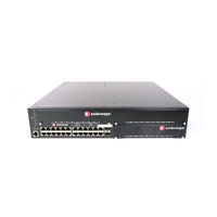
Enterasys G3G124-24 Hardware Installation Manual (59 pages)
G Series
Brand:
Enterasys
| Category:
Network Router
| Size: 2 MB
Table of Contents
Regulatory Compliance Information
4
BSMI EMC Statement - Taiwan
7
VCCI Notice
7
Declaration of Conformity
8
Table of Contents
11
About this Guide
15
Who Should Use this Guide
15
How to Use this Guide
15
Related Documents
15
For Information about
15
Document Conventions
16
Commonly Used Acronyms
16
Getting Help
17
Chapter 1: Introduction
19
Overview
19
Features
20
G3G124-24 Switch (Rear View) with 1200 and 400-Watt Power Supplies Installed
20
Poe (Power over Ethernet) Support
21
Powered Device Classifications (Pds)
22
Fan Management
22
Installation
23
Chapter 2 : Installation
24
Unpacking the G-Series Switch
24
Shipped with the Switch
24
Required and Shipped Separately
24
Optional Enterasys Components
24
Order of Installation Steps
25
G3G124-24 Optional Poe Module Installation Considerations
25
Mounting the Switch
25
Placing the Switch on a Flat Surface
26
Installing the Switch into a Rack
26
Installing and Removing a Power Supply
27
Attaching the Brackets to the Switch (G3G124-24 with G3G-24TX IOM Shown)
27
Power Supply Planning
28
Power Distribution According to Number of Installed Power Supplies
28
Supported Power Configurations
28
Installing a Power Supply
29
Removing a Power Supply
30
Installing a Power Supply Module (1200-Watt Module into PWR 2 Slot Shown)
30
Installing and Removing an IOM
31
Installing an Optional Poe Module on the G3G-24TX
31
Installing an IOM
32
Installing a Poe Module in the G3G-24TX IOM
32
Removing an IOM
33
Installing an IOM (G3G-24TX with Optional Poe Shown)
33
Power Led Displays
34
Connecting Power to the Switch
34
Connecting to the Console Port
35
Connecting to the RJ45 Console Port
35
Connecting to the USB Console Port
36
Connecting to the Network
36
Connecting UTP Cables to RJ45 Ports
36
RJ45 to DB9 Adapter Pinout
36
Connecting a UTP Cable Segment to RJ45 Port
37
Four-Wire Crossover Cable RJ45 Pinouts for 10/100BASE-TX
38
Four-Wire Straight-Through Cable RJ45 Pinouts for 10/100BASE-TX
38
Eight-Wire Crossover Cable RJ45 Pinouts for 10/100/1000BASE-TX
38
Installing Optional SFP/XFP
39
Eight-Wire Straight-Through Cable RJ45 Pinouts for 10/100/1000BASE-TX
39
Installing an SFP/XFP (Shown with LC Connector and Without Dust Cover)
40
Removing an XFP/SFP
41
Connecting Fiber-Optic Cables to SFP/XFP Ports
41
Completing the Installation
42
Cable Connection (LC Shown) to Uplink Port with SFP/XFP Installed
42
Installing an Optional Poe Module in the G3G124-24 Switch
43
Removing the Switch Cover
43
Installing the Poe Module
44
Screw and Coverplate Removal for Removing the G3G124-24 Cover
44
Chapter 3: Troubleshooting
45
Checking the Leds
46
System Led
46
G3 System Leds (G3G124-24 Shown)
46
SYSTEM LED Definitions
46
Power Leds
47
IOM Status Leds
47
Fixed and IOM Port Leds
47
Power LED Definitions
47
IOM Status LED Definitions
47
Port LED Definitions
47
Using the Reset Button
48
Removing the Switch from a Rack
48
Locating the Reset Button
48
Appendix A: Specifications
49
Switch Specifications
49
Regulatory Compliance
49
G3 Switch Specifications
49
IOM Module Specifications
51
G3G-24TX IOM Specifications
51
G3G-24SFP IOM Specifications
51
G3K-2TX and G3K-4TX IOM Specifications
52
Torque Values
53
1-Gigabit Ethernet and 100Base-FX Transceiver (SFP) Specifications
53
Recommended Torque Values by Screw Size
53
Mini-GBIC Input/Output Port Specifications
53
MGBIC-LC01/MGBIC-MT01 Specifications (1000BASE-SX
54
MGBIC-02 Specifications (1000BASE-T
54
MGBIC-LC01/MGBIC-MT01 Optical Specifications
54
MGBIC-LC01/MGBIC-MT01 Operating Range
54
MGBIC-02 Specifications
54
MGBIC-LC03 Specifications (1000BASE-SX
55
MGBIC-LC04 Specifications (100BASE-FX
55
MGBIC-LC03 Optical Specifications
55
MGBIC-LC03 Operating Range
55
MGBIC-LC04 Optical Specifications
55
MGBIC LC04 Operating Range
55
MGBIC-LC05 Specifications (100BASE-FX
56
MGBIC-LC07 Specifications (1000BASE-ELX
56
MGBIC-LC05 Optical Specifications
56
MGBIC LC05 Operating Range
56
MGBIC-LC07 Optical Specifications
56
MGBIC-LC07 Operating Range
56
MGBIC-08 Specifications (1000BASE-ELX
57
MGBIC-LC09 Specifications (1000BASE-LX
57
10-Gigabit Ethernet Transceiver (XFP) Specifications
57
MGBIC-08 Optical Specifications
57
MGBIC-08 Operating Range
57
MGBIC-LC09 Optical Specifications
57
MGBIC-LC09 Operating Range
57
Console Port Pinout
58
XFP Fiber-Optic Specifications
58
Recommended Cable Types and Specifications
58
Console Port Pinout Assignments
58
Regulatory Compliance
58
Compliance Standards
58
Enterasys G3G124-24 Quick Reference (2 pages)
G-Series
Brand:
Enterasys
| Category:
Switch
| Size: 1 MB
Advertisement
Advertisement
Related Products
Enterasys G3G124-24P
Enterasys G3G170-24
Enterasys G3G124P-24
Enterasys GatorMIM and GatorStar
Enterasys GatorMIM
Enterasys Gator Star
Enterasys 2E253-49R
Enterasys 2H23-50R
Enterasys 2H252-25R
Enterasys 2H253-25R
Enterasys Categories
Switch
Network Router
Network Hardware
Wireless Access Point
Software
More Enterasys Manuals
Login
Sign In
OR
Sign in with Facebook
Sign in with Google
Upload manual
Upload from disk
Upload from URL