Honeywell PRO TH4210D Installation Manual
Honeywell programmable thermostat installation guide
Hide thumbs
Also See for PRO TH4210D:
- Installation manual (16 pages) ,
- Operating manual (72 pages) ,
- Installation manual (24 pages)
Table of Contents
Advertisement
Advertisement
Table of Contents

Related Manuals for Honeywell PRO TH4210D


Summary of Contents for Honeywell PRO TH4210D
-
Page 1: Installation Guide
Installation Guide TH4210D Programmable Thermostat... -
Page 2: System Settings
If this product is replacing a control that contains mercury in a sealed tube, do not place the old control in the trash. Contact your local waste management authority for instructions regarding recycling and proper disposal. Copyright © 2005 Honeywell International Inc. All rights reserved. ® U.S. Registered Trademark. Patents pending. -
Page 3: Table Of Contents
Installer setup...7 Installer system test ...7 Installation tips Install the thermostat about 5 feet (1.5m) above the floor in an area with good air circulation at average temperature. Do not install in locations where the thermostat can be affected by: •... -
Page 4: Pre-Installation Checklist
Installation Guide Pre-installation checklist Package contents Check to make sure your package includes the following items: • PRO TH4210D digital thermostat (wallplate attached to back) • Operating manual • Wall anchors and mounting screws (2 each) • AA alkaline batteries (2) •... -
Page 5: Wallplate Installation
PRO TH4210D Programmable Thermostat Wallplate installation Grasp top and bottom of wallplate and pull to remove from thermostat. Drill 3/16” holes for drywall. Drill 7/32” holes for plaster. Wall anchors Remove the wallplate from the ther- mostat as shown at left, then follow directions below for mounting. -
Page 6: Wiring
The C (common wire) terminal is optional when thermostat is powered by batteries. L terminal Heat pump reset. L terminal is powered con- tinuously when thermostat is set to Em Heat. Wire specifications Use 18- to 22-gauge thermostat wire. Shielded cable is not required. -
Page 7: Wiring Diagrams
Optional 24 VAC common connection. Use either O or B terminals for changeover valve. L terminal is powered continuously when thermostat is set to Em Heat. Install field jumper between E and Aux if there is no emergency heat relay. -
Page 8: Battery Installation
“C” terminal Install batteries in back of thermostat (optional if AC powered). AC Power The thermostat can be powered by 24 VAC power, or by batteries. To wire the thermostat for AC power, connect the common side of the transformer to the “C”... -
Page 9: Product View And Buttons
PRO TH4210D Programmable Thermostat Installer setup Follow the procedure below to configure the thermostat to match the installed heating/cooling system, and customize feature operation as desired. Press and hold both buttons To begin, press and hold the buttons until the display changes... - Page 10 System Test Heating system Emergency heat Cooling system Thermostat information (for reference only) CAUTION: EQUIPMENT DAMAGE HAZARD Compressor protection (minimum off time) is bypassed during testing. To prevent equipment damage, avoid cycling the compressor quickly.
-
Page 11: Built-In Compressor Protection
Adaptive Intelligent Recovery Adaptive Intelligent Recovery eliminates guesswork when setting your schedule. It allows the thermostat to “learn” how long your furnace and air conditioner take to reach the temperature you want. Just set your program schedule to the time you want the house to reach your desired temperature.The thermostat then turns on the heating or cooling at just the... -
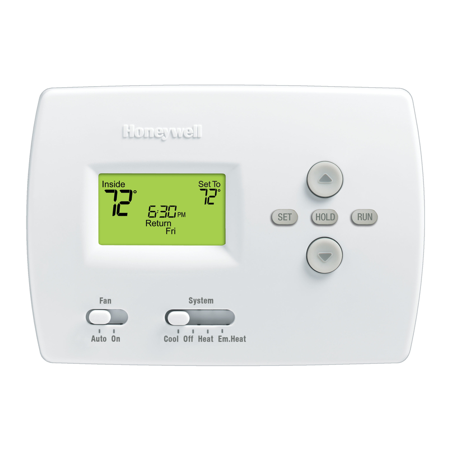
Page 12: Quick Reference To Controls
• Hold: Press to override programmed temperature control. • Run: Press to resume program schedule System switch • Cool: Thermostat controls only the cooling system. • Heat: Thermostat controls only the heating system. • Off: Heating and cooling systems are off. -
Page 13: In Case Of Difficulty
PRO TH4210D Programmable Thermostat In case of difficulty If you have difficulty with your thermostat, please try the suggestions below. Most problems can be corrected quickly and easily. Display is blank • Check circuit breaker and reset if necessary. • Make sure heating & cooling power switches are on. -
Page 14: Accessories
Installation Guide Accessories Please contact your distributor to order accessories. Cover plate assembly ...Part Number 50002883-001 (Used to cover marks left by old thermostats.) Specifications Temperature Ranges • Heat: 40° to 90°F (4.5° to 32°C) • Cool: 50° to 99°F (10° to 37°C) Operating Ambient Temperature •... - Page 16 Printed in U.S.A. on recycled paper containing at least 10% post-consumer paper fibers. ® U.S. Registered Trademark. © 2005 Honeywell International Inc. Patents pending. All rights reserved. 69-1763 • 06-2005 Honeywell Limited-Honeywell Limitée 35 Dynamic Drive Scarborough, Ontario M1V 4Z9...
Need help?
Do you have a question about the PRO TH4210D and is the answer not in the manual?
Questions and answers