
Related Manuals for Honeywell TH401


Summary of Contents for Honeywell TH401
- Page 1 TH401 OWNER’S GUIDE GUIDE DU PROPRIÉTAIRE GUÍA DEL USUARIO Non-programmable Thermostat Thermostat non programmable Termostato no programable 69-2551EFS-03...
- Page 2 Need Help? We are here to help. Call 1-800-468-1502. Besoin d’aide? Nous sommes là. Composez le 1 800-468-1502. ¿Asistencia? Estamos aquí para ayudarlo. Llame al 1 800-468-1502.
-
Page 3: Table Of Contents
TH401 Table of Contents About your new thermostat ............1 Temperature display and setting..........2 Removing the faceplate .............3 Wiring ....................4 Installing the faceplate...............5 Setup procedure................6 Setup menu..................7 In case of difficulty ...............8 Specifications.................9 Warranty ...................10 Customer assistance..............11... -
Page 4: About Your New Thermostat
OWNER’S GUIDE About Your New Thermostat This thermostat can be used to control an electric heating system such as a baseboard heater, a radiant floor, a radiant ceiling, a convector or a fan- forced heater. The thermostat CANNOT be used with: •... -
Page 5: Temperature Display And Setting
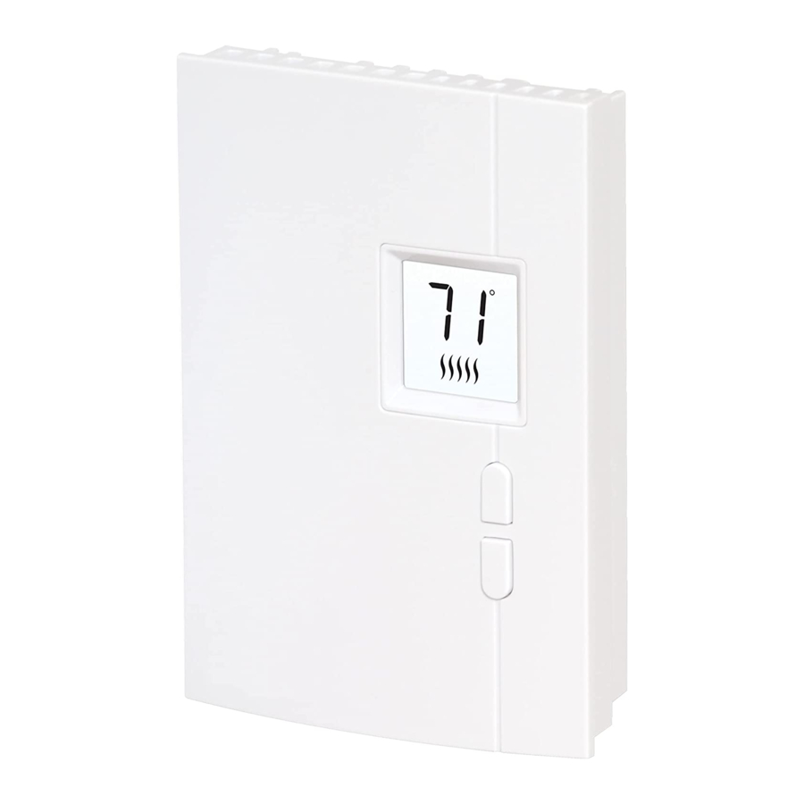
TH401 Temperature Display and Setting Appears when the setpoint is displayed Temperature display Appears when the thermostat is configured for 5-minute cycles. The thermostat must be set to this configuration if it is controlling a fan-forced Up button heater. Down Heating intensity indicator. -
Page 6: Removing The Faceplate
OWNER’S GUIDE Removing the Faceplate TURN OFF POWER OF THE HEATING SYSTEM AT THE MAIN POWER PANEL TO AVOID ELECTRIC SHOCK. Loosen the screw holding the faceplate to the base. The screw cannot be completely removed and remains captive on the base. Remove the faceplate from the base by pulling the bottom half. -
Page 7: Wiring
TH401 Wiring 4-wire installation 2-wire installation Connect any one of thermostat wires to the heater (load) wire and the other one to the power supply wire using solderless connectors for copper wires. (The thermostat wires are non- polarized; either wire can be connected to the load or to the power supply.) -
Page 8: Installing The Faceplate
OWNER’S GUIDE Installing the Faceplate Install the base onto an electrical box. Reinstall the faceplate on the base and secure it in place with the screw. NOTE: Keep the air vents of thermostat clean and unobstructed at all times. -
Page 9: Setup Procedure
TH401 Setup Procedure The setup menu is shown on the following page. 1. Press the Up and Down buttons simultaneously for three seconds to enter the setup menu. 2. Press the Up or Down button to change the option. 3. Press the Up and Down buttons simultaneously for one second to advance to the next parameter. -
Page 10: Setup Menu
OWNER’S GUIDE Table 1. Setup Menu Display and Parameter Options default setting Temperature display °C format °F Cycle length Fan: 5 minutes / Fan-forced heater Std: 15 seconds / Baseboard heater Minimum setpoint 5°C - 20°C (41°F - 68°F) Maximum setpoint 15°C - 30°C (59°F - 86°F) -
Page 11: In Case Of Difficulty
TH401 Table 2. In Case of Difficulty Problem Solutions Thermostat is hot. This is normal. Displayed tem- Remediate if any the following conditions exists: • perature is wrong. The thermostat is exposed to air draft. • The sticker on the thermostat’s screen has not been removed. -
Page 12: Specifications
OWNER’S GUIDE Specifications Supply: 120/240 VAC, 60 Hz Minimum load: 0.83 A (resistive only) 200 W @ 240 VAC 100 W @ 120 VAC Maximum load: 10.4 A (resistive only) 2500 W @ 240 VAC 1250 W @ 120 VAC Display range: 0°C to 50°C (32°F to 122°F) Setpoint range: 5°C to 30°C (41°F to 86°F) Storage: -20°C to 50°C (-4°F to 120°F) -
Page 13: Warranty
TH401 3-Year Limited Warranty Resideo warrants this product, excluding battery, to be free from defects in workmanship or materials, under normal use and service, for a period of three (3) years from the date of first purchase by the original purchaser. If at... - Page 14 OWNER’S GUIDE This warranty does not cover removal or reinstallation costs. This warranty shall not apply if it is shown by Resideo that the defect was caused by damage which occurred while the product was in the possession of a consumer.
- Page 15 TH401 This warranty gives you specific legal rights, and you may have other rights which vary from state to state. If you have any questions concerning this warranty, please write Resideo Customer Care, 1985 Douglas Dr, Golden Valley, MN 55422 or call 1-800-468-1502.
- Page 16 OWNER’S GUIDE...
- Page 17 TH401 Table des matières À propos du thermostat..............1 Affichage et réglage de la température .......2 Enlever la façade................3 Branchement..................4 Installer la façade .................5 Procédé de configuration ............6 Menu de configuration...............7 En cas de difficulté...............8 Fiche technique................9 Garantie ....................10 Service à la clientèle ..............11...
-
Page 18: À Propos Du Thermostat
GUIDE DE L’UTILISATEUR À propos du thermostat Ce thermostat a été conçu pour commander un appareil de chauffage électrique tel qu’une plinthe chauffante, un plancher chauffant, un plafond radiant, un convecteur ou un ventiloconvecteur. Ce thermostat NE PEUT être utilisé avec : •... -
Page 19: Affichage Et Réglage De La Température
TH401 Affichage et réglage de la température Apparaît lorsque la consigne est affichée Affichage de la température Apparaît lorsque le thermostat est configuré pour des cycles de 5 minutes. S’assurer d’utiliser cette Bouton configuration si vous avez un ventiloconvecteur. Haut Bouton Indicateur de l’intensité... -
Page 20: Enlever La Façade
GUIDE DE L’UTILISATEUR Enlever la façade COUPER L’ALIMENTATION DU SYSTÈME DE CHAUFFAGE AFIN D’ÉVITER TOUT RISQUE DE CHOC ÉLECTRIQUE. Desserrer la vis qui retient la façade du thermostat à la base. La vis ne peut être complètement enlevée et reste captive sur la base. -
Page 21: Branchement
TH401 Branchement Installation à 4 fils Installation à 2 fils Relier n’importe quel fil du thermostat au fil de l’appareil de chauffage (charge) et l’autre fil au fil de l’alimentation en utilisant des connecteurs sans soudure pour fils de cuivre. (Les fils du thermostat ne sont pas polarisés;... - Page 22 GUIDE DE L’UTILISATEUR Installer la façade Installer la base sur une boîte électrique. Remettre la façade du thermostat sur la base et resserrer la vis. REMARQUE : Garder les ouvertures d’aération du thermostat propres et dégagées en tout temps.
-
Page 23: Procédé De Configuration
TH401 Procédé de configuration Le menu de configuration apparaît sur la page suivante. 1. Appuyer sur les boutons Haut et Bas simultanément pendant trois sec- ondes pour accéder au menu de configuration. 2. Appuyer sur le bouton Haut ou Bas pour changer d’option. -
Page 24: Menu De Configuration
GUIDE DE L’UTILISATEUR Tableau 1. Menu de configuration Affichage et Paramètre Options réglage par défaut Format d’affichage °C / °F de la température Durée du cycle Fan : 5 minutes / ventiloconvecteur Std : 15 secondes / chauffage conventionnel Consigne minimale 5 °C - 20 °C (41 °F - 68 °F) Consigne maximale 15 °C - 30 °C (59 °F - 86 °F) -
Page 25: En Cas De Difficulté
TH401 Tableau 2. En cas de difiiculté Problèmes Solutions Le thermostat est Ceci est normal. chaud. La température affi- Remédier si l’une des situations suivantes existe : • chée est erronée. Il y a un courant d’air à proximité. •... -
Page 26: Fiche Technique
GUIDE DE L’UTILISATEUR Fiche technique Alimentation : 120/240 V c.a., 60 Hz Charge minimale : 0,83 A (résistive seulement) 200 W @ 240 V c.a. 100 W @ 120 V c.a. Charge maximale : 10,4 A (résistive seulement) 2500 W @ 240 V c.a. 1250 W @ 120 V c.a. -
Page 27: Garantie
TH401 Garantie limitée de 3 ans Resideo garantit ce produit, à l’exception des piles, contre tout défaut de pièce ou de main-d’œuvre, durant une période pour trois (3) ans à partir de la date d’achat par le consommateur d’origine si le produit est utilisé et entretenu convenablement. En cas de défaillance ou de mauvais fonctionnement pendant la période de garantie, Resideo... - Page 28 GUIDE DE L’UTILISATEUR D’UNE VIOLATION QUELCONQUE D’UNE GARANTIE, EXPRESSE OU TACITE, APPLICABLE AU PRÉSENT PRODUIT, OU TOUTE AUTRE DÉFAILLANCE DU PRÉSENT PRODUIT. Certaines provinces ne permettent pas l’exclusion ou la restriction des dommages indirects ou accessoires et, par conséquent, la présente restriction peut ne pas s’appliquer.
- Page 29 TH401 Índice Sobre el nuevo termostato ............1 Visualización y ajuste de la temperatura ......2 Para llevarse la parte frontal ............3 Cableado ..................4 Para instalar la parte frontal ............5 Procedimiento de configuración ..........6 Menú de configuración ..............7 En caso de dificultad..............8 Especificaciones técnicas ............9...
-
Page 30: Sobre El Nuevo Termostato
GUÍA DEL USUARIO Sobre el nuevo termostato Este termostato se puede utilizar para controlar un sistema de calefacción eléctrico, como un calentador de zócalo, un cielorraso o un piso radiante, un convector o un calefactor a aire forzado. El termostato NO se puede usar con: •... -
Page 31: Visualización Y Ajuste De La Temperatura
TH401 Visualización y ajuste de la temperatura Aparece cuando se visualiza el punto de ajuste Pantalla de temperatura Aparece cuando el termostato está configurado para ciclos de 5 minutos. Asegurarse de usar esta configuración con calefacción a aire forzado. Botón Alta Indicador de intensidad de Botón... -
Page 32: Para Llevarse La Parte Frontal
GUÍA DEL USUARIO Para llevarse le parte frontal CORTAR LA ALIMENTACIÓN DEL SISTEMA DE CALEFACCIÓN PARA EVI- TAR RIESGOS DE ELECTROCUCIÓN. Aflojar el tornillo que retiene el frente del termostato a la base. El tornillo no puede retirarse completamente y quedará cautivo en la base. -
Page 33: Cableado
TH401 Cableado Instalación de 4 cables Instalación de 2 cables Conectar uno de los cables del termostato (cualquiera) al cable de carga de la calefacción y el otro al cable de alimentación, utilizando conectores sin soldadura para cables de cobre. (Los cables del termostato no están polarizados;... -
Page 34: Para Instalar La Parte Frontal
GUÍA DEL USUARIO Para instalar la parte frontal Instalar la base en una caja de electricidad. Reponer el frente del termostato sobre la base y asegurarlo con el tornillo. NOTA: mantener siempre las aberturas de aireación del termostato limpias y sin obstrucción. -
Page 35: Procedimiento De Configuración
TH401 Procedimiento de configuración El menú de configuración aparece en página siguiente. 1. Presionar los botones Alta y Baja simultáneamente durante 3 segun- dos para acceder al menú de configuración. 2. Presionar el botón Alta o Baja para cambiar de opción. -
Page 36: Menú De Configuración
GUÍA DEL USUARIO Tabla 1. Menú de configuración Visualización y Parámetro Opciones ajuste de fábrica Formato de la °C / °F temperatura Duración del ciclo Fan: 5 minutos / aire forzado Std : 15 segundos / calefacción convencional Punto de ajuste mínimo 5°C - 20°C (41°F - 68°F) Punto de ajuste máximo 15°C - 30°C (59°F - 86°F) -
Page 37: En Caso De Dificultad
TH401 Tabla 2. En caso de dificultad Problema Soluciones El termostato calienta Esto es normal. La temperatura Puede deberse a alguna de las condiciones siguientes : indicada es incorrecta El termostato está expuesto a una corriente de aire. No se ha retirado el autoadhesivo de la pantalla del termostato. -
Page 38: Especificaciones Técnicas
GUÍA DEL USUARIO Especificaciones técnicas Alimentación: 120/240 V CA, 60 Hz Carga máxima: 0.83 A (resistiva solamente) 200 W @ 240 V CA 100 W @ 120 V CA Carga máxima: 10.4 A (resistiva solamente) 2 500 W @ 240 V CA 1 250 W @ 120 V CA Margen de visualización: 0°C a 50°C (32°F a 122°F) Margen de ajuste: 5°C a 30°C (41°F a 86°F) -
Page 39: Garantía
TH401 Garantía limitada de 3 años Resideo garantiza que este producto, excluyendo la batería, no tiene defectos en la mano de obra ni en los materiales en condiciones de uso y servicio normales durante un período de tres (3) años desde la fecha de compra por parte del comprador original. -
Page 40: Asistencia Al Cliente
GUÍA DEL USUARIO ACCIDENTALES O RESULTANTES DERIVADOS DIRECTA O INDIRECTAMENTE DEL INCUMPLIMIENTO DE LAS GARANTÍAS, EXPRESAS O IMPLÍCITAS, O DE OTRAS FALLAS DE ESTE PRODUCTO. Algunos estados no permiten la exclusión o limitación de los daños accidentales o resultantes, por lo que esta limitación podría no aplicarse en su caso. - Page 41 ICES-003 Class B Notice - Avis NMB-3, Classe B This Class B digital apparatus complies with Canadian ICES-003. Avis ICES-003 de classe B Cet appareil numérique de la classe B est conforme à la norme NMB-3 du Canada. Aviso de clase B según la normativa ICES-003 Este aparato digital de clase B cumple con la normativa canadiense ICES-003.
- Page 42 69-2551EFS—03 M.S. Rev. 08-20 | Printed in United States © 2020 Resideo Technologies, Inc. All rights reserved. The Honeywell Home trademark is used under license from Honeywell International, Inc. This product is manufactured by Resideo Technologies, Inc. and its affiliates.
Need help?
Do you have a question about the TH401 and is the answer not in the manual?
Questions and answers