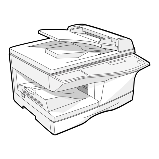
Sharp AL-1661CS Service Manual
Digital multifunctional system
Hide thumbs
Also See for AL-1661CS:
- Operation manual (116 pages) ,
- Operation manual (100 pages) ,
- Operation manual (116 pages)
Table of Contents
Advertisement
[ 1 ] GENERAL . . . . . . . . . . . . . . . . . . . . . . . . . . . . . . . . . . . . . . . . . . . 1 - 1
[ 2 ] SPECIFICATIONS. . . . . . . . . . . . . . . . . . . . . . . . . . . . . . . . . . . . . 2 - 1
[ 3 ] CONSUMABLE PARTS. . . . . . . . . . . . . . . . . . . . . . . . . . . . . . . . . 3 - 1
[ 4 ] EXTERNAL VIEWS AND INTERNAL STRUCTURES . . . . . . . . . 4 - 1
[ 5 ] UNPACKING AND INSTALLATION . . . . . . . . . . . . . . . . . . . . . . . 5 - 1
[ 6 ] COPY PROCESS . . . . . . . . . . . . . . . . . . . . . . . . . . . . . . . . . . . . . 6 - 1
[ 7 ] OPERATIONAL DESCRIPTIONS . . . . . . . . . . . . . . . . . . . . . . . . . 7 - 1
[ 8 ] DISASSEMBLY AND ASSEMBLY . . . . . . . . . . . . . . . . . . . . . . . . 8 - 1
[ 9 ] ADJUSTMENTS . . . . . . . . . . . . . . . . . . . . . . . . . . . . . . . . . . . . . . 9 - 1
[10] TEST COMMAND, FAX SOFT SWITCH, TROUBLE CODES . . 10 - 1
[11] USER PROGRAMS. . . . . . . . . . . . . . . . . . . . . . . . . . . . . . . . . . . 11 - 1
[12] ELECTRICAL SECTION . . . . . . . . . . . . . . . . . . . . . . . . . . . . . . . 12 - 1
[13] CIRCUIT DIAGRAM . . . . . . . . . . . . . . . . . . . . . . . . . . . . . . . . . . 13 - 1
[14] FIRMWARE DOWNLOAD PROCEDURES. . . . . . . . . . . . . . . . . 14 - 1
Parts marked with "
" are important for maintaining the safety of the machine. Be sure to replace these parts
with the replacement parts specified to maintain the safety and performance of the machine.
SERVICE MANUAL
DIGITAL MULTIFUNCTIONAL
SYSTEM
(AL-1661CS)
CONTENTS
SHARP CORPORATION
AL-1661CS
MODEL
CODE : 00ZAL1661CS1E
This document has been published to be used
for after sales service only.
The contents are subject to change without notice.
Advertisement
Table of Contents

Related Manuals for Sharp AL-1661CS


Summary of Contents for Sharp AL-1661CS
-
Page 1: Service Manual
SERVICE MANUAL CODE : 00ZAL1661CS1E DIGITAL MULTIFUNCTIONAL SYSTEM (AL-1661CS) AL-1661CS MODEL CONTENTS [ 1 ] GENERAL ......... . . 1 - 1 [ 2 ] SPECIFICATIONS. - Page 2 CAUTION This product is a class 1 laser product that complies with 21CFR 1040 of the CDRH standard and IEC825. This means that this machine does not produce hazardous laser radiation. The use of controls, adjustments or performance of procedures other than those specified herein may result in hazardous radiation exposure.
- Page 3 At the production line, the output power Caution of the scanner unit is adjusted to 0.57 This product contains a low power laser MILLI-WATT PLUS 20 PCTS and is device. To ensure continued safety do not maintained constant by the operation of remove any cover or attempt to gain access the Automatic Power Control (APC).
-
Page 4: Table Of Contents
9. Software for AL-1661CS ........5-3... - Page 5 [9] ADJUSTMENTS 1. Optical section......... . . 9-1 A.
-
Page 6: General
Turn off the power and keep it for more than 10sec. Then turn on the power. When the machine is booted.: There is no problem in the MCU PWB. When the machine is not booted.: The MCU PWB trouble AL-1661CS GENERAL 1 - 1... -
Page 7: Specifications
Saw -tooth charging with a grid, / (-) scorotron discharge Transfer system (+) DC scorotron system Separation system (-) DC scorotron system Developing Developing system Dry, 2-component magnetic brush development system Cleaning Cleaning system Counter blade system (Counter to rotation) AL-1661CS SPECIFICATIONS 2 - 1... -
Page 8: Copy Performance
Enlarge: 1.5mm or less (OC) / 3.0mm or less (SPF/R-SPF/Duplex) Reduction (50%): 6.0mm or less (OC) / 8.0mm or less (SPF/R-SPF/Duplex) Warm-up time 0 sec. Power save mode reset time 0 sec. Paper jam recovery time 0 sec. AL-1661CS SPECIFICATIONS 2 - 2... -
Page 9: Splc (Jbig Gdi) Printer
Thermal papers, originals with punch holes for files, be used folded paper, transparent originals such as OHP films, stapled or clip used originals with cover up liquid used, Originals with tape sealed, originals with high level frictional coefficient such as photos or catalogs. AL-1661CS SPECIFICATIONS 2 - 3... -
Page 10: Basic Specifications (Fax Section)
Retrieval characters 0 - 3 characters Transmission method Group dial key Address book send Retrieval target • Speed dial • One-touch dial • Group dial Retrieval key SEARCH key Retrieval character 0 - 3 characters AL-1661CS SPECIFICATIONS 2 - 4... - Page 11 Redial is performed according to the setting of (CED/ FSK signal are "Number/ interval of resend in communication error." not detected) Communication error Long document send Supports up to 500mm. When this length is function exceeded, "PAPER JAM" occurs. AL-1661CS SPECIFICATIONS 2 - 5...
- Page 12 Countermeasure against print inhibit state. function • No recording paper • Recording paper jam • During copy/print job • During printing by printer • Cover open • Paper empty, size error Forcible memory receive function Overtake output function AL-1661CS SPECIFICATIONS 2 - 6...
- Page 13 Communication report Report select • Send report list list • Receive report list • Serial broadcast send report list • Image memory addition Print status select • ALWAYS PRINTS • ERROR ONLY • NEVER PRINTS AL-1661CS SPECIFICATIONS 2 - 7...
- Page 14 BEEP LENGTH 3SEC/1SEC/NO BEEP (Communication end sound length) setting Auto summer time First Sunday of April AM2:00 3:00, setting Last Sunday of October AM2:00 1:00 (Default: OFF) Multi language Conforms to the main unit setting. function AL-1661CS SPECIFICATIONS 2 - 8...
-
Page 15: Consumable Parts
(1) Normal operating condition (4) Supply storage condition Temperature:20 - 25°C Humidity (RH) Humidity:65 ± 5%RH (2) Acceptable operating condition Humidity (RH) –5˚C 45˚C 10˚C 30˚C 35˚C (3) Transport condition Humidity (RH) –25˚C 30˚C 40˚C AL-1661CS CONSUMABLE PARTS 3 - 1... -
Page 16: Production Control Number(Lot No.) Identification
(1 - 9 = Jan. - Sep. 0 = Oct. X = Nov. Y = Dec.) Serial number of month Fixed to 1. Pack division (See table below) End digit of year Version No. Division Ex production Option Same pack AL-1661CS CONSUMABLE PARTS 3 - 2... -
Page 17: External Views And Internal Structures
21 LAN port 22 Telephone line port External telephone line port 24 Paper holding arm 2. Internal TD cartridge Drum cartridge Side cover Fusing unit release lever Transfer charger Charger cleaner Front cover AL-1661CS EXTERNAL VIEWS AND INTERNAL STRUCTURES 4 - 1... -
Page 18: Operation Panel
Press this key to send duplex document. 33 [SHIFT] key 34 [SPEAKER] key Used in combination with the one-touch key to select one-touch Press this key to allow manual dialing. destination umber 10 – 18. AL-1661CS EXTERNAL VIEWS AND INTERNAL STRUCTURES 4 - 2... -
Page 19: Motors And Solenoids
10 Original feed solenoid SPUS Original pick up solenoid 11 SPF paper feed solenoid SPFS Original feed solenoid 12 SPF gate solenoid Controls the document reverse gate. 13 Shifter motor SFTM Drives the shifter. AL-1661CS EXTERNAL VIEWS AND INTERNAL STRUCTURES 4 - 3... -
Page 20: Sensors And Switches
SPPD sensor SPPD Transmission sensor Paper transport detection "L" at paper pass 10 PD1 sensor Micro-switch Paper width detect "H" at B4 size or less "L" at B4 size or more AL-1661CS EXTERNAL VIEWS AND INTERNAL STRUCTURES 4 - 4... -
Page 21: Pwb Unit
TCS PWB For toner sensor control LSU PWB For laser control (In the LSU) NIC PWB 10 BASE-T Network I/F 10 FAX-operation PWB FAX operation input 11 Modem PWB FAX control AL-1661CS EXTERNAL VIEWS AND INTERNAL STRUCTURES 4 - 5... -
Page 22: Cross Sectional View
Picks up a sheet of paper from the cassette. 15 Pickup roller Picks up documents. 16 Separation roller Separates documents to feed properly. 17 PS roller Feeds documents to the scanning section. 18 Paper exit roller Discharges documents. AL-1661CS EXTERNAL VIEWS AND INTERNAL STRUCTURES 4 - 6... -
Page 23: Unpacking And Installation
Software CD-ROM Be sure to allow the required space around the machine for servicing and proper ventilation. 8" (20cm) 8"(20cm) Telephone line cord Drum cartridge (installed in machine) 4" 4" (10cm) (10cm) TD cartridge AL-1661CS UNPACKING AND INSTALLATION 5 - 1... -
Page 24: Unpacking
7) Ensure that the power switch of the machine is in the OFF position. Plug the other end of the power cord into the nearest outlet. AL-1661CS UNPACKING AND INSTALLATION 5 - 2... -
Page 25: Loading The Paper Tray
• When loading paper, ensure that there is no space between the paper and the guide, and make sure that the guide is not set too nar- row and causes the paper to bend. Incorrect loading will cause the paper to skew or misfeed. AL-1661CS UNPACKING AND INSTALLATION 5 - 3... -
Page 26: A. Before Installation
"Next" button. • The scanner feature only works when using a USB cable. Click the "Display README" button to show information on pack- ages that are selected. AL-1661CS UNPACKING AND INSTALLATION 5 - 4... - Page 27 If "Continue" is selected, Sharpdesk Imaging will be installed. Caution: If Imaging for Windows is installed on your computer, Sharp- • USB is available with a PC/AT compatible computer that was origi- desk nally equipped with USB and had Windows 98, Windows Me, Win- Imaging will overwrite Imaging for Windows.
- Page 28 Note: If the language selection screen appears after you double click the "setup" icon, select the language that you wish to use and click the "Next" button. (Normally the correct language is selected automatically.) AL-1661CS UNPACKING AND INSTALLATION 5 - 6...
- Page 29 If any of the entries are incorrect, click the "Back" button to return to the appropriate window and correct the entry. 9) Read the message in the "Welcome" window and then click the "Next" button. AL-1661CS UNPACKING AND INSTALLATION 5 - 7...
-
Page 30: C. Setting Up Button Manager
Windows logo test or digital signature, be sure to click "Continue Anyway" or "Yes". 16) When "This installation of the SHARP software is complete" appears, click the "OK" button. 8) For the port to be used, select the machine set as a shared printer, 17) When the "Finish"... - Page 31 Select "SC2:" from the "Scanner events" pull-down menu. Select each ScanMenu through "SC6:". "Sharp Button Manager B" in "Send to this application" and click the When the settings have been completed, click the "OK" button to "Apply" button. Do the same for each ScanMenu through "SC6:".
-
Page 32: Interface
7) Close the multi-bypass tray and the paper output tray extension, and attach the packing materials and tape which were removed during installation of the unit. 8) Pack the unit into the carton. AL-1661CS UNPACKING AND INSTALLATION 5 - 10... -
Page 33: Copy Process
Waste toner box To face Synchronization Paper release Fusing Separation Transfer Manual feed down tray with drum Heat roller Electrode Transfer charger Cassette paper feed Transfer high Heater lamp voltage unit Print process Paper transport route AL-1661CS COPY PROCESS 6 - 1... -
Page 34: Outline Of Print Process
A uniform negative charge is applied over the OPC drum surface by Aluminum the main charging unit. Stable potential is maintained by means of the layer Scorotron charger. Non-image area Image area Positive charges are generated in the aluminum layer. About DC5.5KV ( 580V/ 400V) AL-1661CS COPY PROCESS 6 - 2... - Page 35 Toner remaining on the drum is removed and collected by the cleaning blade. It is transported to the waste toner collecting section in the cleaning unit by the waste toner transport roller. Toner is attracted over the shadowed area because of the developing bias. AL-1661CS COPY PROCESS 6 - 3...
- Page 36 Voltage added to the screen grid can be selected, high and low. To make it easily understood, the figure below shows voltage transition at the developer unit. START STOP Print potential Toner attract Developing bias potential Drum potential High Time AL-1661CS COPY PROCESS 6 - 4...
-
Page 37: Operational Descriptions
5) The LSU emits laser beams according to the print data. (Electrical signals are converted into photo signals.) 6) The laser beams are radiated through the polygon mirror and vari- ous lenses to the OPC drum. AL-1661CS OPERATIONAL DESCRIPTIONS 7 - 1... -
Page 38: Scanner Section
473 through the idle gear, the pulley gear, the belt 190, and the idle pulley to drive the optical unit. Scanner motor Pulley gear Idle pulley Belt 473 Belt 190 Optical unit Shaft Idle gear AL-1661CS OPERATIONAL DESCRIPTIONS 7 - 2... -
Page 39: Laser Unit
(Refer to the figure below.) Makes the laser scanning speeds at both ends of the drum same as each other. d = e = f f LENS AL-1661CS OPERATIONAL DESCRIPTIONS 7 - 3... -
Page 40: A. General Description
Level of the thermistor is controlled by the main PWB. Triac (in the power supply unit) With the signal from the main PWB, the triac is controlled on and off. (power supply PWB) AL-1661CS OPERATIONAL DESCRIPTIONS 7 - 4... - Page 41 4) After more than half rotation of the pick-up roller, the paper feed latch is brought in contact with a notch on the clutch sleeve, stopping rotation of the pick-up roller. AL-1661CS OPERATIONAL DESCRIPTIONS 7 - 5...
- Page 42 (Refer to A-5 - 8.) roller is pressed to the surface of the paper to start paper feeding. 5) The solenoid turns off to close the gate and return to the initial state. MPFS MPFS AL-1661CS OPERATIONAL DESCRIPTIONS 7 - 6...
-
Page 43: Process Unit New Drum Detection Mechanism
7. RSPF section Process detection switch A. Outline The RSPF (Reverse Single Path Feeder) is installed to the AL-1661CS as a standard provision, and it automatically copies up to 30 sheets of documents of a same size. (Only one set of copies) B. -
Page 44: C. Operational Descriptions
Mylar attached to the paper exit guide (document scanning sec- tion) by the scanner (CCD) and detecting the varied quantity. (Floating) (White Mylar) Reference line Reference line (CCD) A - B = Varied quantity of pixels (pixel) AL-1661CS OPERATIONAL DESCRIPTIONS 7 - 8... -
Page 45: C. Back Copy
The front and the back are not in upside down. 9. Shifter Shift width: 2.5cm The offset function by the shifter is turned ON/OFF by the user pro- gram. According to the setting, offset operation is performed for every job. (Default: ON) AL-1661CS OPERATIONAL DESCRIPTIONS 7 - 9... -
Page 46: Disassembly And Assembly
For assembly, reverse the disassembly procedure. Charger wire D. Charger wire cleaning B. Disassembly procedure 1) Remove the charger cleaner from the manual paper feed unit. 1) Press the side cover open/close button and open the side cover. AL-1661CS DISASSEMBLY AND ASSEMBLY 8 - 1... -
Page 47: E. Charger Wire Replacement
• The rest of the charger wire must be within 1.5mm. Refer to Fig.1 • The spring hook section (charger wire winding section) must be in the range of the projection section. • Be careful not to twist the charger wire. Charger wire Protrusion 1.5mm Fig.1 AL-1661CS DISASSEMBLY AND ASSEMBLY 8 - 2... -
Page 48: C. Assembly Procedure
7) Remove the table glass. 3. Optical section A. List Part name Ref. Copy lamp unit Copy lamp Lens unit B. Disassembly procedure 1) Remove four screws, and remove the rear cabinet and the rear cabinet cover. AL-1661CS DISASSEMBLY AND ASSEMBLY 8 - 3... -
Page 49: C. Assembly Procedure
12) Remove the rod. Note: Attach the FCC to Marking line. fit with the marking line. 13) Lift the rear side of the carriage, remove the belt and the connec- tor, and remove the carriage. AL-1661CS DISASSEMBLY AND ASSEMBLY 8 - 4... -
Page 50: Fusing Section
6) Remove the screw and remove the PPD2 sensor. 3) Cut the binding band, remove the screw, and remove the ther- mistor. PPD2 sensor Thermistor AL-1661CS DISASSEMBLY AND ASSEMBLY 8 - 5... - Page 51 8) Remove the spring and remove the separation pawls (3 pcs.). Heat roller disassembly (Continued from procedure (4).) 5) Remove screws, remove the fusing cover, and open the heat roller section. 9) Remove the E-ring and remove the reverse gate. AL-1661CS DISASSEMBLY AND ASSEMBLY 8 - 6...
-
Page 52: Tray Paper Feed/Transport Section
2) Remove the two screws, and remove the hinge guide R. 3) Remove the fan duct and disconnect the connector. (2 positions) 4) Remove the six screws, and remove the scanner unit. C. Assembly procedure For assembly, reverse the disassembly procedure. AL-1661CS DISASSEMBLY AND ASSEMBLY 8 - 7... - Page 53 11) Remove the paper exit roller, and remove the belt, the pulley, and the bearing. 7) Remove the screw, and open the upper paper guide. 12) Remove the connector and the screw, and remove the speaker unit. 8) Remove the roller, and remove the belt. AL-1661CS DISASSEMBLY AND ASSEMBLY 8 - 8...
- Page 54 16) Remove the three screws, and remove the MCU PWB. 20) Remove the five screws and the grounding wire, and remove the main drive unit. 17) Remove two screws and remove the toner motor. CAUTION:Attach the gears securely AL-1661CS DISASSEMBLY AND ASSEMBLY 8 - 9...
- Page 55 22) Remove each pawl, and remove the paper exit tray. [Note for installation] Fit the lower paper guide hole (a) with the shifter gear hole (b) so that the black resin (c) of the shifter unit can be checked. AL-1661CS DISASSEMBLY AND ASSEMBLY 8 - 10...
- Page 56 29) Remove the E-ring, the gear, and the bearing, and remove the shifter roller. Note: When assembling, turn it to the right and attach. 30) Put the lower paper guide unit upside down, remove the two screws, and remove the shifter motor. AL-1661CS DISASSEMBLY AND ASSEMBLY 8 - 11...
-
Page 57: C. Assembly Procedure
38) Remove the semi-circular roller unit. 39) Remove the semi-circular rubber. 35) Remove the screw and the connector, and remove the PPD1 sen- sor PWB. C. Assembly procedure For assembly, reverse the disassembly procedure. AL-1661CS DISASSEMBLY AND ASSEMBLY 8 - 12... -
Page 58: Manual Paper Feed Section
1) Remove the screw and remove the multi upper cover. 4) Remove two screws and remove the multi feed bracket unit from the multi paper feed upper frame. 2) Remove the screw and remove the side door detection unit. Back Wire treatment AL-1661CS DISASSEMBLY AND ASSEMBLY 8 - 13... -
Page 59: D. Pressure Plate Holder Attachment
For assembly, reverse the disassembly procedure. D. Pressure plate holder attachment 1) Attach the pressure plate holder so that the resin section is not covered with the seal M1-N. Seal M1-N Pressure plate holder Attachment reference Attachment reference AL-1661CS DISASSEMBLY AND ASSEMBLY 8 - 14... -
Page 60: Rear Frame Section
5) Remove two screws, and remove the scanner motor. 10) Disconnect the connector. 11) Remove the two screws, and remove the NIC PWB unit. 6) Remove two screws and one harness, and remove the main motor. AL-1661CS DISASSEMBLY AND ASSEMBLY 8 - 15... -
Page 61: Power Section
Part name Ref. Reverse roller B. Disassembly procedure 1) Remove four screws 2) Remove the spring, and the earth wire 3) Remove the reverse unit. C. Assembly procedure For assembly, reverse the disassembly procedure. AL-1661CS DISASSEMBLY AND ASSEMBLY 8 - 16... -
Page 62: Rspf Section (Rspf Model Only)
2) Remove the upper cover. A. RSPF (1) Remove the rear cabinet. 1) Remove four screws. 2) Remove the rear cabinet. (2) Remove the RSPF. 1) Remove the connector and the cable. 2) Remove the RSPF. AL-1661CS DISASSEMBLY AND ASSEMBLY 8 - 17... -
Page 63: D. Pickup Unit
E. Upper cover of the pickup unit. 1) Remove two screws from the bottom of the pickup unit. 2) Remove the upper cover. Note: When reassembling, hang the iron core on the solenoid arm. AL-1661CS DISASSEMBLY AND ASSEMBLY 8 - 18... -
Page 64: H. Clutch
(2) Remove the Manual paper feed roller, pickup roller. 2) Remove the parts. 1) Remove the parts. 2) Remove the manual paper feed roller. 3) Remove the pickup roller. 4) Remove the parts. AL-1661CS DISASSEMBLY AND ASSEMBLY 8 - 19... -
Page 65: J. Transport Unit Removal
1) Remove the harness. 2) Remove two screws. 3) Remove the SPF motor. K. Belt 1 1) Remove the belt. N. Solenoid 1) Remove the harness. 2) Remove two screws. 3) Remove the solenoid. AL-1661CS DISASSEMBLY AND ASSEMBLY 8 - 20... -
Page 66: O. Clutch
2) Open the paper exit paper guide. 3) Remove the paper entry sensor. P. Paper supply roller 4) Remove the harness. (1) Remove the parts. 1) Remove the two screws. 2) Remove the parts. AL-1661CS DISASSEMBLY AND ASSEMBLY 8 - 21... -
Page 67: R. Transport Roller 1
(2) Remove the parts. 1) Loosen the screw. 2) Open the paper exit paper guide. 3) Remove the parts. S. Paper exit roller (1) Remove the parts. 1) Remove two screws. 2) Remove the parts. AL-1661CS DISASSEMBLY AND ASSEMBLY 8 - 22... -
Page 68: T. Solenoid
1) Remove the parts. positions of the spring. 2) Remove the paper exit roller. Note: When reassembling, hang 2) on the solenoid. (2) Remove the solenoid. 1) Remove the screw. 2) Remove the solenoid. AL-1661CS DISASSEMBLY AND ASSEMBLY 8 - 23... -
Page 69: Adjustments
1) Set the scale on the document table as shown below. (Use a long scale for precise adjustment.) 2) Set the copy magnification ratio to 100%. 3) Make a copy on A4 or 81/2" x 11" paper. 4) Measure the length of the copied scale image. AL-1661CS ADJUSTMENTS 9 - 1... -
Page 70: B. Image Position Adjustment
When the value of B is increased by 10, the void is extended by SCAN mode lamp about 0.1mm. (For 25 or less, however, the void amount is regarded as 0.) * The SFP adjustment is made by adjusting the SPF image scan start position after OC adjustment. AL-1661CS ADJUSTMENTS 9 - 2... -
Page 71: Copy Density Adjustment
1) Arrangement before execution of the copy density adjustment • Clean the optical section. • Clean or replace the charger wire. • Check that the voltage at the high voltage section and the developing bias voltage are in the specified range. AL-1661CS ADJUSTMENTS 9 - 3... -
Page 72: C. Necessary Tool For Copy Density Adjustment
Brightness 1 step only Check the adjustment level (shown in the above table) of the Manual Mode Brightness 5 steps. Adjustment of only the center exposure test chart (Sharp Gray Scale). brightness is made. Sharp Gray Scale adjustment level Photo Mode Brightness 5 steps. -
Page 73: High Voltage Adjustment
An increase of 1 in setting represents an increase of 0.1 mm in image loss. Front edge of paper The front edge of the scale on test chart Void area 5 10 less than 4 mm AL-1661CS ADJUSTMENTS 9 - 5... -
Page 74: B. Adjusting Trailing Edge Void In Duplex Copy Mode
4) Make a copy and check the void area of the scale on the image. Adjust the setting so that the void area is 2 - 4 mm. An increase of 1 in setting represents an increase of 0.1 mm in void area. l Void position to be checked AL-1661CS ADJUSTMENTS 9 - 6... -
Page 75: Spf (Rspf) Scan Position Automatic Adjustment
Reduce 1: 0.1% below. ratio (SPF/RSPF decrease Chart size: 300 x 100, prepared with cutting sheet No. 791 (Black) or mode) an equivalent one. Reason: To prevent erroneous detection by disturbing light of a fluorescent lamp, etc. AL-1661CS ADJUSTMENTS 9 - 7... -
Page 76: Automatic Black Level Correction
After canceling, the machine goes into the sub code entry standby mode. THE JOB IS BEING CANCELED. 3) After execution 63-02 BLACK LEVEL *** OK 3) In case of an error 63-02 BLACK LEVEL *** ERR AL-1661CS ADJUSTMENTS 9 - 8... -
Page 77: Test Command, Fax Soft Switch, Trouble Codes
Scanner mode counter clear (S-MODE CLR.) Main charger output (Grid LOW) (MHV(L) SET.) Main motor operation check (MAIN MOTOR CHK) Transfer charger output (THV SET.) Polygon motor operation check (LSU CHK) AL-1661CS TEST COMMAND, FAX SOFT SWITCH, TROUBLE CODES 10 - 1... - Page 78 Copier color reproduction setting (COLOR REAPPEAR) FAX mode sharpness adjustment Mains can/sub scan direction magnification ratio (COPY MAG.) SPF/RSPF mode sub scan direction magnification ratio in copying (SPF/RSPF MAG.) AL-1661CS TEST COMMAND, FAX SOFT SWITCH, TROUBLE CODES 10 - 2...
-
Page 79: Descriptions Of Various Test Commands
(SPF MOTOR CHK) When [ENTER/START] key is pressed, the motor rotates for 10sec at the speed corresponding to the set magnification ratio. [Operation] The operation is similar to test command 1-01. AL-1661CS TEST COMMAND, FAX SOFT SWITCH, TROUBLE CODES 10 - 3... - Page 80 02-10 RSPF SGS CHK EXECUTING... Shifter operation check [Function] (SHIFTER CHK) The shifter is moved back and forth in four reciprocations. [Operation] 1) Initial display 03-03 SHIFTER CHK EXECUTING... AL-1661CS TEST COMMAND, FAX SOFT SWITCH, TROUBLE CODES 10 - 4...
- Page 81 05-02 HT LAMP CHK EXECUTING... Copy lamp ON check [Function] (C-LAMP CHK) When [ENTER/START] key is pressed, the copy lamp turns ON for 5sec. [Operation] 1) Initial display 05-03 C-LAMP CHK EXECUTING... AL-1661CS TEST COMMAND, FAX SOFT SWITCH, TROUBLE CODES 10 - 5...
- Page 82 After completion of warm-up, counting is terminated. (The aging function is removed from test com- mand 7-01.) [Operation] 1) Initial display 2) After 10sec 07-08 W-UP C-MODE 07-08 W-UP C-MODE AL-1661CS TEST COMMAND, FAX SOFT SWITCH, TROUBLE CODES 10 - 6...
- Page 83 1) Initial display /10KEY] 3) [ENTER/START] 09-04 DPLX ROT.SPEED 09-04 DPLX ROT.SPEED 09-04 DPLX ROT.SPEED 6( 1-13) 7( 1-13) 7( 1-13) 2) [ /10KEY] 09-04 DPLX ROT.SPEED 5( 1-13) AL-1661CS TEST COMMAND, FAX SOFT SWITCH, TROUBLE CODES 10 - 7...
- Page 84 RECV PAGE:xxx,xxx RX TIME:xxxx:xx.xx ("xxx,xxx" is the current value.) ("xxxx: xxx. xx" is the current value.) [CLEAR] key: Returns to "1) Initial display". [CLEAR] key: Returns to "1) Initial display". AL-1661CS TEST COMMAND, FAX SOFT SWITCH, TROUBLE CODES 10 - 8...
- Page 85 The scanner mode counter is displayed. [Operation] 1) Initial display 22-19 S-MODE CNT ***,*** Scanner counter display [Function] (SCAN CNT) The scanner counter is displayed. [Operation] 1) Initial display 22-21 SCAN CNT ***,*** AL-1661CS TEST COMMAND, FAX SOFT SWITCH, TROUBLE CODES 10 - 9...
- Page 86 When PRINT switch is pressed, the FAX count value is set to 0 and "000,000" is displayed on the LCD. [Operation] 1) Initial display 24-10 FAX CLR. CLEARED 000,000 AL-1661CS TEST COMMAND, FAX SOFT SWITCH, TROUBLE CODES 10 - 10...
- Page 87 SPF and press [ENTER/START] key to save the setting. Code number Display item SPF NO SPF OFF SPF YES SPF ON RSPF YES RSPF ON [Operation] The operation is similar to test command 21-01. AL-1661CS TEST COMMAND, FAX SOFT SWITCH, TROUBLE CODES 10 - 11...
- Page 88 Code number Setting Display item Remark CE mark support control OFF Default (100V series) CE mark support control ON [Operation] The operation is similar to test command 21-01. AL-1661CS TEST COMMAND, FAX SOFT SWITCH, TROUBLE CODES 10 - 12...
- Page 89 The default “5” of transfer ON timing is “330ms passed from PS release.” When set to “0,” it is the same as setting to “5.” [Operation] The operation is similar to test command 21-01. AL-1661CS TEST COMMAND, FAX SOFT SWITCH, TROUBLE CODES 10 - 13...
- Page 90 Since the manual paper feed sensor is a single bypass sensor, its status is not displayed. The width sensor is available only in the FAX models. [Operation] 1) Initial display 2) When sensor ON 30-01 P-SENSOR 30-01 POD PPD1 PPD2 PPD3 DRST AL-1661CS TEST COMMAND, FAX SOFT SWITCH, TROUBLE CODES 10 - 14...
- Page 91 When this test command is executed, the current set code number is displayed. Enter the code num- ber and press [ENTER/START] key to change the setting. Code Set temperature (°C) Remark Default [Operation] The operation is similar to test command 21-01. AL-1661CS TEST COMMAND, FAX SOFT SWITCH, TROUBLE CODES 10 - 15...
- Page 92 Press [ / /10KEY] to switch the setting, and press [ENTER/START] key to save it to the EEPROM. The machine goes to the sub code entry standby mode. Code Set temperature (°C) Remark Default [Operation] The operation is similar to test command 21-01. AL-1661CS TEST COMMAND, FAX SOFT SWITCH, TROUBLE CODES 10 - 16...
- Page 93 TS mode (TEXT) (600dpi) TSTXT PRINT mode lampSCAN mode lamp TS mode (AE) (600dpi) TSAE COPY mode lampSCAN mode lamp [Operation] The operation is similar to test command 46-01. AL-1661CS TEST COMMAND, FAX SOFT SWITCH, TROUBLE CODES 10 - 17...
- Page 94 2) Enter a 2-digit value as the exposure adjust- After completion of printing, returns to “2)” ment value with [10KEY]. display. ADJUST EXP. FINE ("YY" is the entered exposure adjustment value.) AL-1661CS TEST COMMAND, FAX SOFT SWITCH, TROUBLE CODES 10 - 18...
- Page 95 PRINT mode lamp SCAN mode lamp TS mode (AE) (300dpi) TSAE COPY mode lamp SCAN mode lamp No density display on LCD. [Operation] The operation is similar to test command 46-01. AL-1661CS TEST COMMAND, FAX SOFT SWITCH, TROUBLE CODES 10 - 19...
- Page 96 When the set value is increased, copy becomes darker. When the set value is decreased, copy becomes lighter. (Adjustment range: 1 – 99) Mode Display item Default Remark [Operation] The operation is similar to test command 46-01. AL-1661CS TEST COMMAND, FAX SOFT SWITCH, TROUBLE CODES 10 - 20...
- Page 97 TS mode (TEXT) TSTXT PRINT mode lamp SCAN mode lamp TS mode (AE) TSAE COPY mode lamp SCAN mode lamp [Operation] The operation is similar to test command 46-01. AL-1661CS TEST COMMAND, FAX SOFT SWITCH, TROUBLE CODES 10 - 21...
- Page 98 ("ZZZZ" is the mode selected among STD, FINE, S-FINE, FINE/PHOTO, and S-FINE/ PHOTO.) ("X" is the corresponding sharpness adjustment value of the selected mode stored on the FAX side.) [CLEAR] key: Returns to “2)” display. AL-1661CS TEST COMMAND, FAX SOFT SWITCH, TROUBLE CODES 10 - 22...
- Page 99 RSPF document *1 When there is no document in SPF, copy is inhibited. *1: Only when RSPF is installed. If installed, skipped. [Operation] The operation is similar to test command 46-01. AL-1661CS TEST COMMAND, FAX SOFT SWITCH, TROUBLE CODES 10 - 23...
- Page 100 To enter the download mode, there is a method to use key operations as well as to use a test com- mand. With the power OFF, press and hold [CA] + [ ], turn on the power. [Operation] 1) Initial display DOWNLOAD MODE AL-1661CS TEST COMMAND, FAX SOFT SWITCH, TROUBLE CODES 10 - 24...
- Page 101 Distance from the paper lead edge to the image lead edge, H = 5mm Image loss, R = 4mm 10mm [Operation] The operation is similar to test command 46-01. AL-1661CS TEST COMMAND, FAX SOFT SWITCH, TROUBLE CODES 10 - 25...
- Page 102 SCAN mode lamp (*) : Support for the installation models. For non-installation models, skip. When paper is discharged, the shifter is operated. [Operation] The operation is similar to test command 46-01. AL-1661CS TEST COMMAND, FAX SOFT SWITCH, TROUBLE CODES 10 - 26...
- Page 103 The initial value for duplex setting is "1to2/Short Edge" for the OC/SPF setting, or "2to2" for the RSPF setting. When paper is discharged, the shifter is operated. [Operation] The operation is similar to test command 46-01. AL-1661CS TEST COMMAND, FAX SOFT SWITCH, TROUBLE CODES 10 - 27...
- Page 104 When [ENTER/START] key is pressed, HSYNC is performed and the polygon motor is rotated for 30sec. At that time, the COPY mode lamp is lighted for 100msec every time when HSYNC is detected. [Operation] 1) Initial display 61-03 LSU CHK EXECUTING... AL-1661CS TEST COMMAND, FAX SOFT SWITCH, TROUBLE CODES 10 - 28...
- Page 105 2) [ENTER/START] Correction start THE JOB IS BEING CANCELED. 63-02 BLACK LEVEL 3) After execution EXECUTING... 63-02 BLACK LEVEL *** OK 3) In case of an error 63-02 BLACK LEVEL *** ERR AL-1661CS TEST COMMAND, FAX SOFT SWITCH, TROUBLE CODES 10 - 29...
- Page 106 After 2sec, returns to "1) Initial display". FAX soft SW initializing [Function] (excluding the adjustment Use to initializing FAX soft SW. values) [Operation] 1) Initial display INITIALIZED After 2sec, FAX control is terminated. AL-1661CS TEST COMMAND, FAX SOFT SWITCH, TROUBLE CODES 10 - 30...
- Page 107 35:LINE ON HOOK [CLEAR] key: FAX control is terminated. 3) [ENTER] key Send after setting OUTPUTING SIGNAL MAX PRESS CLEAR TO STOP [CLEAR] key: Returns to "1) Initial display". AL-1661CS TEST COMMAND, FAX SOFT SWITCH, TROUBLE CODES 10 - 31...
- Page 108 After completion of memory clear, the buzzer After completion of memory clear sounds. CLEARED CLEARED PLEASE POWER OFF After 2sec, FAX control is terminated. Remains unchanged until the power is turned off. AL-1661CS TEST COMMAND, FAX SOFT SWITCH, TROUBLE CODES 10 - 32...
- Page 109 SELECT SIGNAL (1-6) 1:NO SIGNAL 6:00001 [CLEAR] key: FAX control is terminated. 3) [ENTER] key OUTPUTING SIGNAL SSW PRESS CLEAR TO STOP [CLEAR] key: Returns to "1) Initial display". AL-1661CS TEST COMMAND, FAX SOFT SWITCH, TROUBLE CODES 10 - 33...
- Page 110 PRESS CLEAR TO STOP [CLEAR] key: FAX control is terminated. [CLEAR] key: Returns to "1) Initial display". 2) [10KEY] input The content selected with signal send level selection is set inside. AL-1661CS TEST COMMAND, FAX SOFT SWITCH, TROUBLE CODES 10 - 34...
- Page 111 Use to check the TEL/LIU status change. [Operation] 1) Initial display HS2 :xxx HS1 :xxx RHS :xxx EXHS:xxx The disdplay is switched every 2sec. CHECKING PRESS CLEAR TO STOP [CLEAR] key: FAX control is terminated. AL-1661CS TEST COMMAND, FAX SOFT SWITCH, TROUBLE CODES 10 - 35...
- Page 112 When [ ] key is pressed, the sequence is reversed. SELECT (1-4) SELECT (1-4) ..1:NO SOUND 2:LOW [CLEAR] key: FAX control is terminated. 3) [ENTER] key STORED xxx: Set content After 2sec, FAX control is terminated. AL-1661CS TEST COMMAND, FAX SOFT SWITCH, TROUBLE CODES 10 - 36...
- Page 113 [Function] Use to check the CI signal. When CI signal is detected, OFF [Operation] 1) Initial display CHECKING CI:OFF PRESS CLEAR TO STOP [CLEAR] key: FAX control is terminated. AL-1661CS TEST COMMAND, FAX SOFT SWITCH, TROUBLE CODES 10 - 37...
-
Page 114: Fax Soft Switch Setting Change Quick Reference Table
Automatic reduction print User program SW 24-8 When reduction print is not made Index Index print setup User program SW 32-6 When an index is attached to the reception data AL-1661CS TEST COMMAND, FAX SOFT SWITCH, TROUBLE CODES 10 - 38... -
Page 115: Soft Switch List
“RECALL INTERVAL Bit No. 5 6 7 8 (BUSY)”. Set range 1 to 15min 3min When a value outside the set range is set, the initial value is set. AL-1661CS TEST COMMAND, FAX SOFT SWITCH, TROUBLE CODES 10 - 39... - Page 116 0 When a value outside number the set range is set, Bit No. 3 4 5 6 7 8 the initial value is set. Set range Pattern No. 1 to 35 AL-1661CS TEST COMMAND, FAX SOFT SWITCH, TROUBLE CODES 10 - 40...
- Page 117 Refer to User program “RINGER VOLUME”. Silent Small Medium Medium Large Speaker volume in Bit No. DTMF send Not used Small Medium Medium Large Inhibited to use Inhibited to use AL-1661CS TEST COMMAND, FAX SOFT SWITCH, TROUBLE CODES 10 - 41...
- Page 118 ECM JBIG (in SG3) 1: Yes 0: No Inhibited to use Inhibited to use Recording table 1: Yes 0: No Refer to User program automatic print “AUTO LISTING”. Inhibited to use AL-1661CS TEST COMMAND, FAX SOFT SWITCH, TROUBLE CODES 10 - 42...
- Page 119 1000Hz 1700Hz Reception end sound Bit No. When a value outside tone the set range is set, 550Hz 1000Hz the initial value is set. 1000Hz 1700Hz AL-1661CS TEST COMMAND, FAX SOFT SWITCH, TROUBLE CODES 10 - 43...
- Page 120 Default data, sender 1: ON 0: OFF print Inhibited to use Date/sender print 1: Inside of document 0: Outside of document Outside of position setup document Inhibited to use AL-1661CS TEST COMMAND, FAX SOFT SWITCH, TROUBLE CODES 10 - 44...
- Page 121 Refer to User program print “DUPLEX RCV”. Inhibited to use Signal send level Max. Binary input Bit No. 5 6 7 8 –8dBm Set range 0 (0dBm) to 15 (–15dBm) AL-1661CS TEST COMMAND, FAX SOFT SWITCH, TROUBLE CODES 10 - 45...
- Page 122 1 2 3 4 5 6 7 8 (LINE ERROR)”. Set range 0 to 1 times When a value outside 1 times the set range is set, the initial value is set. AL-1661CS TEST COMMAND, FAX SOFT SWITCH, TROUBLE CODES 10 - 46...
- Page 123 Scan effective image Binary input area main scan right Bit No. 5 6 7 8 96 dots edge image loss (SPF) Set range 0 to ± 360 dots 24 dot interval AL-1661CS TEST COMMAND, FAX SOFT SWITCH, TROUBLE CODES 10 - 47...
- Page 124 0 When a value outside pattern number the set range is set, Bit No. 3 4 5 6 7 8 the initial value is set. Set range Pattern No. 1 to 35 AL-1661CS TEST COMMAND, FAX SOFT SWITCH, TROUBLE CODES 10 - 48...
- Page 125 1 2 3 155ms Set range 0 (155ms) to 7 (225ms) Inhibited to use DT/BT detection Bit No. frequency range Modem fixed (400Hz) 420Hz–680Hz 420Hz–680Hz 360Hz–440Hz 245Hz–650Hz Inhibited to use AL-1661CS TEST COMMAND, FAX SOFT SWITCH, TROUBLE CODES 10 - 49...
- Page 126 CI signal OFF time in 1: 2sec 0: 1sec 1sec V.8 mode V.8 mode ANSam Bit No. signal send time 3sec 4sec 4sec 5sec 6sec Inhibited to use AL-1661CS TEST COMMAND, FAX SOFT SWITCH, TROUBLE CODES 10 - 50...
- Page 127 3sec 2sec 4sec 5sec Inhibited to use T1 timer setup Binary input Bit No. 5 6 7 8 40sec Set range 30 to 105sec 5sec interval Inhibited to use AL-1661CS TEST COMMAND, FAX SOFT SWITCH, TROUBLE CODES 10 - 51...
- Page 128 Binary input area sub scan lead Bit No. 1 2 3 4 32 lines edge void Set range 0 to 240 lines 16 line interval (600dpi) Inhibited to use AL-1661CS TEST COMMAND, FAX SOFT SWITCH, TROUBLE CODES 10 - 52...
- Page 129 Language information Binary input 0 Only command receive from the main Bit No. 1 2 3 4 5 6 7 8 unit can be rewritten. 1: American English American English AL-1661CS TEST COMMAND, FAX SOFT SWITCH, TROUBLE CODES 10 - 53...
- Page 130 3 4 5 6 7 8 the initial value is set. Set range Pattern No. 1 to 35 Inhibited to use Inhibited to use Inhibited to use Inhibited to use Inhibited to use AL-1661CS TEST COMMAND, FAX SOFT SWITCH, TROUBLE CODES 10 - 54...
- Page 131 1: Enable 0: Disable Enable enable in V.34 send Symbol speed 2743 1: Enable 0: Disable Enable enable in V.34 send Inhibited to use Inhibited to use Inhibited to use AL-1661CS TEST COMMAND, FAX SOFT SWITCH, TROUBLE CODES 10 - 55...
- Page 132 Print effective image Binary input area sub scan rear edge Bit No. 5 6 7 8 48 lines void (Back surface) Set range 0 to 240 lines 16 line interval (600dpi) AL-1661CS TEST COMMAND, FAX SOFT SWITCH, TROUBLE CODES 10 - 56...
- Page 133 Scan magnification ratio 1: – 0: + adjustment (SPF back Binary input surface sub scan) Bit No. 2 3 4 5 6 7 8 Set range 0 to ±12.7% 0.1% interval AL-1661CS TEST COMMAND, FAX SOFT SWITCH, TROUBLE CODES 10 - 57...
-
Page 134: Soft Switch Descriptions
This is because ANSam signal send is necessary for V.34 mode. When set to 1, CED signal send is performed. When set to 0, CED signal send is not performed. Default: 1 (Yes) AL-1661CS TEST COMMAND, FAX SOFT SWITCH, TROUBLE CODES 10 - 58... - Page 135 SW10 No.7, No.8 Inhibited to use SW11 No.1–No.8 Scanner resource holding time out in direct send Used to set time-out time to hold scanner resource in direct send. Default: 26sec AL-1661CS TEST COMMAND, FAX SOFT SWITCH, TROUBLE CODES 10 - 59...
- Page 136 Used to set whether the FAX receive rejection function is made valid or nication other than SG3. not for registered FAX numbers. Default: 1 (Yes) Default: 0 0 (Not set.) SW24 No.5 Inhibited to use AL-1661CS TEST COMMAND, FAX SOFT SWITCH, TROUBLE CODES 10 - 60...
- Page 137 Used to set whether the user cancel report is outputted or not when When auto clear is made by pressing C/A key, the machine returns to send is canceled during document send. this setting. Default: 0 (Not output) Default: 0 (No) AL-1661CS TEST COMMAND, FAX SOFT SWITCH, TROUBLE CODES 10 - 61...
- Page 138 When set to 2400bps, all of SW91 No. 1 – 8 must be set as "Disable". Setting is made in binary input. Default: 33600bps When set to 0, recall is not made. Default: 1 times AL-1661CS TEST COMMAND, FAX SOFT SWITCH, TROUBLE CODES 10 - 62...
- Page 139 When, however, the number of recall in case of a send error is 0, this SW47 No.1 Inhibited to use function does not operate. Default: 0 (Super G3 disabled) AL-1661CS TEST COMMAND, FAX SOFT SWITCH, TROUBLE CODES 10 - 63...
- Page 140 Default: 0 1 (420Hz–680Hz) Used to set ANSam/CED signal send time. SW56 No.7, No.8 Inhibited to use Default: 0 1 (4sec) SW57 No.1 Inhibited to use SW62 No.6–No.8 Inhibited to use AL-1661CS TEST COMMAND, FAX SOFT SWITCH, TROUBLE CODES 10 - 64...
- Page 141 FAX receive state to when CED/ANSam signal is send Setting is made in binary input in the increment of 0.1%. to the line. Default: 0% Default: 0 0 (2.25sec) AL-1661CS TEST COMMAND, FAX SOFT SWITCH, TROUBLE CODES 10 - 65...
- Page 142 3000Hz is selected in V.34 send. Setting is made in binary input in the increment of 16 lines. When high/low carriers are "disable", 3200Hz cannot be selected. Default: 96 lines Default: 1 (Enable) AL-1661CS TEST COMMAND, FAX SOFT SWITCH, TROUBLE CODES 10 - 66...
-
Page 143: Trouble Codes
Polygon motor lock detection FAX board battery error EEPROM read/write error (Serial communication error) Counter check sum error (EEPROM) Operation panel language error AL-1661CS TEST COMMAND, FAX SOFT SWITCH, TROUBLE CODES 10 - 67... - Page 144 The fusing unit is not installed. Check Check the harness and the connector between the thermistor and the PWB. remedy Use TC 14 to clear the self diagnostic display. AL-1661CS TEST COMMAND, FAX SOFT SWITCH, TROUBLE CODES 10 - 68...
- Page 145 MCU PWB. Replace the battery. Replace the mirror unit. remedy Replace the MCU PWB. When the mirror does feed. Use TC 1-2 to check the mirror home position sensor. AL-1661CS TEST COMMAND, FAX SOFT SWITCH, TROUBLE CODES 10 - 69...
-
Page 146: Communication Error Codes
An interruption command is other party sending an interface entered with the interruption command. key. Power OFF Power OFF during transmission or reception (Recording paper empty) AL-1661CS TEST COMMAND, FAX SOFT SWITCH, TROUBLE CODES 10 - 70... - Page 147 RTN, RTP PRI-Q No signal EOR-Q PPS-PRI-Q V.8 Phase-1 V.8 Phase-1 V.8 Phase-2 V.8 Phase-2 V.8 Phase-3 V.8 Phase-3 (Note) For error codes 16 – 31, V.34 mode communication. AL-1661CS TEST COMMAND, FAX SOFT SWITCH, TROUBLE CODES 10 - 71...
-
Page 148: User Programs
3: 1.0 SEC. changed by the accidental pressing of a key. 4: 1.5 SEC. 5: 2.0 SEC. KEY TOUCH 1: LOW • This sets the volume of beep signals. SOUND 2: HIGH 3: OFF AL-1661CS USER PROGRAM 11 - 1... -
Page 149: B. Print Mode
NOTE: • If you mistakenly select the wrong item, press the [CLEAR] key [C] and repeat the procedure from step 2. • To cancel a setting for a user program, press the [MENU] key. AL-1661CS USER PROGRAM 11 - 2... -
Page 150: Electrical Section
[12] ELECTRICAL SECTION 1. Block diagram A. Overall block diagram AL-1661CS ELECTRICAL SECTION 12 - 1... -
Page 151: Circuit Descriptions
DGND /CPUSYNC Interruption Horizontal sync (ASIC) ESSRDY Input E-sort control level input ESCRDY Output E-sort control DGND AVcc CPU3.3V DGND Vref CPU3.3V Interruption Zero cross signal Analog Fusing thermistor level input input AL-1661CS ELECTRICAL SECTION 12 - 2... - Page 152 64Mb or 128Mb CCD-RS,CCD-CK1,CCD-CK2 to CCD(SCAN UNIT) CCD-CP,CCD-SHR (Op.400MByte) bsmp,vsmp,mclk,OEB afesen,afesck,afesdi to AFE(SCAN UNIT) AFE-DB[7..0] to USB I/F to IEEE1284 I/F MIRCNT,MTR-Y1,MTR-PH-1,MTR-I01,MTR-I11,MTR-I21 MTR-Y2,MTR-PH-2,MTR-I02,MTR-I12,MTR-I22 to MIRROR MOTOR DRIVER SYNC to LSU-PWB to CCFL(Scan UNIT) LEND CPUSYNC AL-1661CS ELECTRICAL SECTION 12 - 3...
- Page 153 Tr array IC Transfer charger signal control signal. "H":ON ope_latch Tr array IC Operation circuit latch gridl Tr array IC Main charger grid signal. Data take-in at control signal. "H": L "L" output GND_AC Power AL-1661CS ELECTRICAL SECTION 12 - 4...
- Page 154 160 GND_core Power connector communication port) 161 out_req Not used 123 vpout I/F board VPOUT signal (USB 162 in_ack Not used connector communication port) 163 in_cs Not used 124 GND_core Power 164 GND_AC Power AL-1661CS ELECTRICAL SECTION 12 - 5...
- Page 155 252 GND_AC Power signal 253 ram_data7 IN/OUT SDRAM SDRAM (Image 223 GND_core Power process page 224 mtr_y3 Carriage motor memory) data bus current control signal 225 mtr_y2 Tr array IC Carriage motor current control signal AL-1661CS ELECTRICAL SECTION 12 - 6...
- Page 156 SDRAM's clock 277 GND_core Power 278 ram_mad12 SDRAM SDRAM (Image process page memory) address bus 279 ram_mad11 SDRAM SDRAM (Image process page memory) address bus 280 ram_mad9 SDRAM SDRAM (Image process page memory) address bus AL-1661CS ELECTRICAL SECTION 12 - 7...
- Page 157 When the thermistor terminal voltage falls below the set level, the output signal HL from ASIC becomes LOW level. LOAD b. The HL signal becomes LOW, the power PWB photo triac coupler LOAD turns OFF, and the heater lamp turns OFF. AL-1661CS ELECTRICAL SECTION 12 - 8...
- Page 158 Each motor is driven in W1-2 phase excitement, 1-2 phase excitement, or 2-phase excitement. The mirror motor/SPF motor related to image scan are driven by a con- stant current, and each motor current is switched in each magnification ratio. AL-1661CS ELECTRICAL SECTION 12 - 9...
- Page 159 DMT1 /SFTMT1 (11-A1) R339 /DMT2 (11-B3) (4-B2) SFTMT1 (1-D3) DMT2 /SFTMT2 (11-A1) R340 /DMT3 (11-B3) (4-B2) SFTMT2 /SFTMT3 (11-A1) (1-D3) DMT3 24VDup R341 (4-B2) SFTMT3 24VSFT MTZ J22B TD62064AF MTZ J22B TD62064AF PGND PGND AL-1661CS ELECTRICAL SECTION 12 - 10...
-
Page 160: B. Dc Power Circuit
The normal noise means that overlapped in the AC line or the output line. It is attenuated by C023, C001, L002, C004, and L003. Refer to fig (2). fig (3) Rush current prevention, rectifying/smoothing circuit fig (2) Noise filter circuit AL-1661CS ELECTRICAL SECTION 12 - 11... - Page 161 The high frequency pulse generated by the inverter circuit is decreased by the converter transformer, rectified by the high frequency diode D113, and smoothed by C107 and C108. Voltage waveform Voltage waveform fig (7) +5V rectifying/smoothing circuit voltage waveform AL-1661CS ELECTRICAL SECTION 12 - 12...
-
Page 162: Circuit Diagram
P10/PO8/TIOCA0/DACK0 (4-C3) PG0/CAS PG1/CS3 PG2/CS2 BR110 /CS3# /CS3 /CS2# /CS2 /CS1# /CS1 /CS0# /CS0 Reset IC VCC3 VCC3 VCC3 0.1u 11kF 3.3kJ /RESET0 (2-C4) 10kF M51957BFP 0.1u OPEN RESETOUT1 (8-A1) (9-B2) /ASIC_RST (2-D1) 10kJ AL-1661CS CIRCUIT DIAGRAM 13 - 1... - Page 163 (FW) (FW) (4-D4) (8-A2) 0.1u CPU_SYNC CPU_SYNC (2-B1) MT_HOME mt_at_home (14-C3) 10kJ CCD_TG CCD_TG (2-A4) (14-D3) (SPPD) (SPPD) (7-E1) (PSW) (PSW) (7-E1) 24WC02 (4-A1) OPEN SDA1 (4-B1) A[19..0] (2-A1) (3-A3) VCC3 ZJSR5101-223 CPU3.3 10u/16V AL-1661CS CIRCUIT DIAGRAM 13 - 2...
- Page 164 (3-E2) SDCLK GND(AC) R351 CPUDATA15 CPUDATA14 CPUDATA13 C397 CPUDATA12 0.1u CPUDATA11 CPUDATA10 CPUDATA9 CPUDATA8 VCC3 ZJSR5101-223 SFCLK48 OUTPUT 0.1u N.C. OSC-31 48MHz HC-49U/S (16.1511MHz) (13-C2) (4-A2) (3-A1) (1-D2) D[15..0] PFCLKIN (3-A3) (1-C1) A[19..0] PFCLKOUT AL-1661CS CIRCUIT DIAGRAM 13 - 3...
- Page 165 PARAD4 (5-B3) CPFS2 OUTP05B PARAD5 PARAD6 PARAD7 BR59 10kJ /INIT /SLCTIN /AUTOF D /STB VCC3 R352 33J (/ASIC_RST) R353 N.M. /RESET1 R358 10kJ R354 N.M. /OA_RST (9-B2) SYNC# (/SYNC) (4-D4) R355 C398 /FWREN N.M. AL-1661CS CIRCUIT DIAGRAM 13 - 4...
- Page 166 I/O7 DQ12 HWRZ /RESET0 VCC3 VCC3 DQ11 (1-D3) RY/BY RY/BY DQ10 CS1Z (1-A2) /CS1 0.1u 0.1u (15-B2) (2-C1) (1-B3) HWRZ (1-B3) /HWR IS63LV1024L-12J-TR Flash ROM (15-C2) (4-A2) (2-A1) (1-D2) D[15..0] Flash ROM LH28F400BVE-BL85 OPEN AL-1661CS CIRCUIT DIAGRAM 13 - 5...
- Page 167 N.M. SDRAM (16bit x 4bank) /CS0 (1-A2) VCC3 0.1u 0.1u 0.1u 0.1u 0.1u 0.1u 0.1u 0.1u MAD[12..0] (2-A3) SDRAM Vendor/Type LH28F800BJE-PBTL90 128Mb(2Mx16bitx4bank) MT48LC8M16A2TG-75(Micron) HY57V281620HCT(Hyndai) K4S281632E-TC75(Samsung) W981216BH-75(Winbond) HY57V641620HGT-P Hyndai) 64Mb(1Mx16bitx4bank) MT48LC4M16A2TG-75 Micron) K4S641632F-TC75(Samsung) K4S641632E-TC1H(Samsung) W986416DH-7(Winbond) AL-1661CS CIRCUIT DIAGRAM 13 - 6...
- Page 168 (1-D3) R349 (1-D3) LCDDB5 R350 TC7SBD385AFU (1-D3) LCDDB4 (1-D3) LCDE C103 (1-D3) LCDRS 0.1u /RESET0 /RESET# R308 R309 10kJ 10kJ EN5V 3.3V IC20 (1-E2) (SCL1) (11-D3) EN5V NC7ST08M5X C109 0.1u For CRUM Model Only AL-1661CS CIRCUIT DIAGRAM 13 - 7...
- Page 169 (SELIN3) (4-A4) (10-E3) (KEYSC1) (10-E3) (KEYSC2) (10-E3) (KEYSC3) (10-E3) (TM) (6-D2) (TM_) (6-D2) 74VHCT244 VCC3 3.3V IC19 (LCDDB7) (10-E3) (LCDDB6) (10-E3) (LCDDB5) (10-E3) (LCDDB4) (10-E3) (LCDE) (10-E3) (LCDRS) (10-E3) R323 /RESET# R324 /RESET1 74LCX244 AL-1661CS CIRCUIT DIAGRAM 13 - 8...
- Page 170 MRPS_3 SRRC# (2-C1) LDEN /LDEN (2-D1) (5-E3) KID65503F TD62064AF PGND For SPF/DSPF Model Only IC27 (2-C1) /MMD (2-A3) MM_Y1 MMref0 (2-A3) MM_Y2 MMref1 (2-C1) MM_Y3 MMref2 (1-D3) POFF /POFF (2-C1) /PMD (2-C1) /LEND KID65503F AL-1661CS CIRCUIT DIAGRAM 13 - 9...
- Page 171 KIA393F MCLK_A (11-B2) RPS_1 (6-A1) THOPEN (4-A4) RPS_2 (6-A1) (6-A1) RPS_3 (11-B2) C114 10kF 22000p 240J 240J HLOUT (10-B3) IC24B KIA358F (11-A4) Mref0 (6-A3) 10kJ Mref1 (6-A3) KRC106S Mref2 (6-A3) SHOLD (11-B2) (10-B4) (11-B2) AL-1661CS CIRCUIT DIAGRAM 13 - 10...
- Page 172 2200p (5-C2) MRPS_1 In A (5-C2) MRPS_2 In /B PGND (5-C2) MRPS_3 In B R114 1J 2W PGND R115 C136 MTD1361/F OPEN PGND C137 OPEN PGND (4-D3) (SPFMT2) (4-D3) (SPFMT0) (4-D3) (SPFMT3) (4-D3) (SPFMT1) AL-1661CS CIRCUIT DIAGRAM 13 - 11...
- Page 173 Tonner Motor Driver C128 C129 10u/35V 0.1u/50V PGND IC32 R105 (11-E1) PSAVE (11-D1) (4-D3) (TM) OUT1 TMB_O (11-A1) (11-D1) (4-D3) (TM_) OUT2 TMA_O (11-A1) (11-E1) VREF R106 R112 R113 47kJ 47kJ PGND BA6920FP PGND AL-1661CS CIRCUIT DIAGRAM 13 - 12...
- Page 174 0.1u/50V OUT 3 INT5V PGND C189 C190 KIA7805 47u/35V 0.1u ZJSR5101-223 ZJSR5101-223 (10-A4) 12VIN (10-B4) 3.3VIN VCC3 C191 C193 C192 C194 47u/25V 0.1u 22u/16V 0.1u EN5V C195 C197 C196 C198 22u/16V 0.1u 22u/16V 0.1u AL-1661CS CIRCUIT DIAGRAM 13 - 13...
- Page 175 (10-E4) (PSW) (1-D2) R157 (11-B4) CED1 (CED1) (4-A4) R158 (11-D2) CED2 (CED2) (4-A3) R159 (10-E4) DRST (DRST) (4-A4) VCC3 C199 C200 C201 C202 C203 C204 1000p 1000p 1000p 1000p 1000p 1000p KDS226 KDS226 KDS226 AL-1661CS CIRCUIT DIAGRAM 13 - 14...
- Page 176 TRST_L TRST_L TRST_L VSS_IO TRST_L VSS_IO R233 OPEN TEST_MODE0 R234 OPEN TEST_MODE1 R235 4.7KJ VSS_CORE R236 4.7KJ VSS_CORE VSS_CORE VSS_CORE VSS_CORE VSS_CORE VSS_CORE C300 XOUT VSS_CORE 32.3022MHz R237 XOUT OA-982 CLK_EXT (8-A3) CLK_EXT C306 AL-1661CS CIRCUIT DIAGRAM 13 - 15...
- Page 177 BR115 10kJX4 C297 C298 C299 _SDRAM_DATA1 _SDRAM_CS0_L 0.1U 0.1U 0.1U _SDRAM_DATA2 _SDRAM_DATA3 C265 _SDRAM_DATA4 BR116 10kJX4 _SDRAM_DATA5 _SDRAM_DATA6 _SDRAM_CKE _SDRAM_DATA7 _SDRAM_DATA8 BR117 10kJX4 _SDRAM_DATA9 _SDRAM_DATA10 _SDRAM_DATA11 _SDRAM_DATA12 BR118 10kJX4 _SDRAM_DATA13 _SDRAM_DATA14 _SDRAM_DATA15 R238 4.7KJ AL-1661CS CIRCUIT DIAGRAM 13 - 16...
- Page 178 /RESET (8-A3) PB_NCS3 (8-A2) INT_USBD (8-A3) (13-C3) PB_NAE0 (8-A2) DT_REQB DREQ NC7S08M5X (8-A2) DT_ACKB DACK PB_NOE (13-C3) (8-A3) PB_NOE PB_NWE (13-C3) (8-A3) PB_NWE VCC3 IC43 ISP1581 R303 R304 100P NC7S04M5X R305 NM AGND MLF1608-J AL-1661CS CIRCUIT DIAGRAM 13 - 17...
- Page 179 R290 10KJ 10KJ C329 XTAL1 (8-A2) USBVBUS 12MHz XTAL2 C330 BLM21PG600SN1 Vreg(3.3) R293 1.5KJ CN33 SHIELD L15 DLW21SN900SQ2 RREF UBR23(ACON) R301 NM USB2.0 DEV1 R302 12KF C331 0.01U BLM21PG600SN1 FGND_UD2 AGND_UD2 AGND_UD2 MLF1608-J FGND_UD1 AL-1661CS CIRCUIT DIAGRAM 13 - 18...
- Page 180 MCU PWB (Connector section 1) To Power unit INT5V INT24V (5-C4) /BIAS (5-C4) (5-C4) /GRIDL (5-C4) 3.3VIN (7-B2) EN5V /POFF (5-C1) (7-A2) 12VIN (7-A2) (4-C4) (5-C3) HLOUT (5-D2) B24B-PHDSS-B C207 C208 0.1u/50V 0.1u/50V PGND PGND AL-1661CS CIRCUIT DIAGRAM 13 - 19...
- Page 181 (4-C4) KEYIN (PSL) (OP_CLK) C205 (OP_LATCH) (OP_DATA) 1000p (SELIN1) (SELIN2) (SELIN3) (LCDDB7) (LCDDB6) (LCDDB5) (LCDDB4) (LCDE) (LCDRS) (BZR) (KEYSC1) (KEYSC2) (KEYSC3) 28FE-BT-VK-N To Mirror motor (6-A4) OUT_A+ (6-A4) OUT_B+ (6-A4) OUT_A- OUT_B- (6-A4) B4B-PH-K-R AL-1661CS CIRCUIT DIAGRAM 13 - 20...
- Page 182 AL-1661CS CIRCUIT DIAGRAM 13 - 21...
- Page 183 AL-1661CS CIRCUIT DIAGRAM 13 - 22...
- Page 184 AL-1661CS CIRCUIT DIAGRAM 13 - 23...
- Page 185 AL-1661CS CIRCUIT DIAGRAM 13 - 24...
-
Page 186: Fax Main Pwb
9.31kF(1608) R1002 B0.68u/16V C1003 C15 B0.01u/250V(N.M.) 78.7F(1608) R1001 215F(1608) 402F(1608) R1003 B1800p/50V C1004 2200pF(KH) 2200pF(KH) RD43FM ZD1001 150(1608) R1017 2W(N.M.) 1.78kF 100kF(1608) 1/4W 5.36kF R1027 1/4W 536kF R1028 DSS-401M DSS-401M 1/4W 5.36kF R1019 DSS-401M AL-1661CS CIRCUIT DIAGRAM 13 - 25... - Page 187 R1041 F0.1u/16V(N.M.) C1030 F0.1u/16V(N.M.) C1029 F0.1u/16V(N.M.) C1027 R1037 R1034 R1033 R1039 AL-1661CS CIRCUIT DIAGRAM 13 - 26...
- Page 188 AL-1661CS CIRCUIT DIAGRAM 13 - 27...
- Page 189 REGOUT REGOUT VDD2 VDD2 VDD2 VDD2 VDD2 VDD2 VDDREG VDDREG VDD3 FL12 VDD3 FL11 VDD3 VDD3 VDD3 AVSS VDD3 VDD3 AVDD AL-1661CS CIRCUIT DIAGRAM 13 - 28...
- Page 190 AL-1661CS CIRCUIT DIAGRAM 13 - 29...
- Page 191 33pF C1053 100pF C1059 33pF C1064 10p/50V(N.M.) C1040 33pF C1052 100pF 10p/50V C1035 33pF C1063 10p/50V(N.M.) C1038 33pF C1051 10p/50V 10p/50V C1045 F0.1u/16V 33pF C1062 10p/50V(N.M.) C1046 33pF C1050 10p/50V C1036 10p/50V(N.M.) C1047 A47u/25V AL-1661CS CIRCUIT DIAGRAM 13 - 30...
-
Page 192: Operation Pwb
3. OPERATION PWB AL-1661CS CIRCUIT DIAGRAM 13 - 31... - Page 193 AL-1661CS CIRCUIT DIAGRAM 13 - 32...
- Page 194 AL-1661CS CIRCUIT DIAGRAM 13 - 33...
-
Page 195: Fax Operation
4. FAX OPERATION AL-1661CS CIRCUIT DIAGRAM 13 - 34... - Page 196 /DREQ1 /AFEED VCC 14 /AFEED /DREQ1 A3 13 /O3 12 CVSS HVDD BR21 /AFEED3 A4 11 AVSS HVDD /AFEED3 10kJ /O4 10 AVREF AVDD A5 9 TCLR0 /O5 8 TCLR0 /DACK0 /DACK0 74VHC14 UPD703100GJ-33-8EU AL-1661CS CIRCUIT DIAGRAM 13 - 35...
- Page 197 VCCINT (/RESET) (/RESET) VCCIO CLKOUT CLKOUT VCCIO GNDINT GNDINT /CSPRN /CSPRN GNDIO /DACK0 /DACK0 GNDIO /IOWR /IOWR GNDIO BR27 GNDIO /CSRAM /CS1 /CSRAM EPM3032ATC44-10 0.1U IS16C256AH-12 VCC3 0.1U /SELIN3 /SELIN3 /SELIN /SELIN /IT3 /IT3 AL-1661CS CIRCUIT DIAGRAM 13 - 36...
- Page 198 NICINT INT0 INT1 INT2 INT3 INT4 ET5V INT5 INT6 INT7 /CSNIC /CSNIC /NWAIT /NWAIT IOCHRDY IOCS16B IORB IOWB NICRST NICRST RSTDRV SMEMRB SMEMWB 27kJ RTL8019AS ET5V ZJSR5101-102TA 10U/16V 0.1U 0.1U 0.1U 0.1U 0.1U 0.1U AL-1661CS CIRCUIT DIAGRAM 13 - 37...
- Page 199 P[7:0] /RESET To MCU PWB /PACK /PACK PBSY PBSY PERR PERR SLCT SLCT /FLT /FLT /STB /STB /AFEED3 /AFEED3 /SELIN3 /SELIN3 /IT3 /IT3 DIR3 DIR3 OPEN 24FMN-SSTK-A OPEN IC45 (/RESET) /RESET 0.1u OPEN NC7WZ17 AL-1661CS CIRCUIT DIAGRAM 13 - 38...
-
Page 200: Power Supply
6. POWER SUPPLY POWER SUPPLY (120V/127V) AL-1661CS CIRCUIT DIAGRAM 13 - 39... - Page 201 AL-1661CS CIRCUIT DIAGRAM 13 - 40...
-
Page 202: Actual Wiring Diagram
7. ACTUAL WIRING DIAGRAM (1) MCU SECTION (1/3) AL-1661CS CIRCUIT DIAGRAM 13 - 41... - Page 203 (2) D-SPF SECTION (2/3) AL-1661CS CIRCUIT DIAGRAM 13 - 42...
- Page 204 (3) NIC & FAX SECTION (3/3) AL-1661CS CIRCUIT DIAGRAM 13 - 43...
-
Page 205: Firmware Download Procedures
"Download DWL Data Area" in the sub trees. 4) PC side: Check that the "test command list" tree is displayed on the integration maintenance program. AL-1661CS FIRMWARE DOWNLOAD PROCEDURES 14 - 1... -
Page 206: Version Acquisition Procedures
Turn OFF the power of the machine, and disconnect the USB menu bar. cable. 12) Terminate the integration maintenance program, and turn ON the machine again. Download is completed with the above procedures. AL-1661CS FIRMWARE DOWNLOAD PROCEDURES 14 - 2... -
Page 207: Eeprom Data Acquisition Procedure
"MCU Boot Version: 00.08." Note: For models without FAX, the facsimile data version is not down- loaded and always displayed as "**.**." AL-1661CS FIRMWARE DOWNLOAD PROCEDURES 14 - 3... -
Page 208: Serial Number Setting
LCD of the operation panel. (Only to set the serial number, the PC should not be connected to 2) Connect the machine and the PC with a USB cable. the machine.) AL-1661CS FIRMWARE DOWNLOAD PROCEDURES 14 - 4... - Page 209 5) Select the folder which includes the maintenance tool driver (Jaguar2s.inf) and press <OK> button. (Suppose that the driver is included in C:\Drivers\2kXp folder.) With the above procedures, installation (on Windows XP) of the inte- gration maintenance program is completed. AL-1661CS FIRMWARE DOWNLOAD PROCEDURES 14 - 5...
- Page 210 8) Check that the path to the folder which includes the maintenance tool driver (jaguar2.inf) is displayed, and press <OK> button. (Suppose that the maintenance tool driver is included in C:\Driv- ers\2kXp folder.) 5) Select [Specify a location] and press <Next> button. AL-1661CS FIRMWARE DOWNLOAD PROCEDURES 14 - 6...
- Page 211 3) The following display is shown on the PC side. Select [Specify the location of the driver], and press <Next> button. With the above procedures, installation (on Windows ME) of the inte- gration maintenance program is completed. AL-1661CS FIRMWARE DOWNLOAD PROCEDURES 14 - 7...
- Page 212 Memo...
- Page 213 Memo...
- Page 214 LEAD-FREE SOLDER The PWB’s of this model employs lead-free solder. The “LF” marks indicated on the PWB’s and the Service Manual mean “Lead-Free” solder. The alphabet following the LF mark shows the kind of lead-free solder. Example: <Solder composition code of lead-free solder> Solder composition Solder composition code Solder composition...
- Page 215 CAUTION FOR BATTERY REPLACEMENT (Danish) ADVARSEL ! Lithiumbatteri – Eksplosionsfare ved fejlagtig håndtering. Udskiftning må kun ske med batteri af samme fabrikat og type. Levér det brugte batteri tilbage til leverandoren. (English) Caution ! Danger of explosion if battery is incorrectly replaced. Replace only with the same or equivalent type recommended by the manufacturer.
- Page 216 Adobe, the Adobe logo, Acrobat, and the Acrobat logo are trademarks of Adobe Systems Incorporated. All other trademarks and copyrights are the property of their respective owners. SHARP CORPORATION Digital Document System Group Products Quality Assurance Department Yamatokoriyama, Nara 639-1186, Japan...
Need help?
Do you have a question about the AL-1661CS and is the answer not in the manual?
Questions and answers