Table of Contents
Advertisement
Advertisement
Table of Contents

Related Manuals for Honeywell HCE 60


Summary of Contents for Honeywell HCE 60
- Page 1 Storey Controller HCE 60 Installation and Operation...
-
Page 3: Table Of Contents
Contents Overview Application Installation procedure Classifying zones and actuators Installation Configuration and electrical connection Start-up Creating a zoning plan Determining temperature zones Filling out zoning plan Installation Wall installation DIN rail installation Installing Hometronic components Configuration and electrical connection Opening housing Cabling connections Start-up Preparing for start-up... - Page 4 Assigning zones and issuing room names Example: Assigning an HCW 22 setpoint adjuster to zone 1 Example: Assigning room name LIVING to zone 1 Assigning wireless setpoint adjuster HCU 30 to a temperature zone Assigning setpoint adjusters of type HCW 23 to a zone Assigning room names for cooling function Canceling assignment Deleting assignment of a room name at the Hometronic...
-
Page 5: Overview
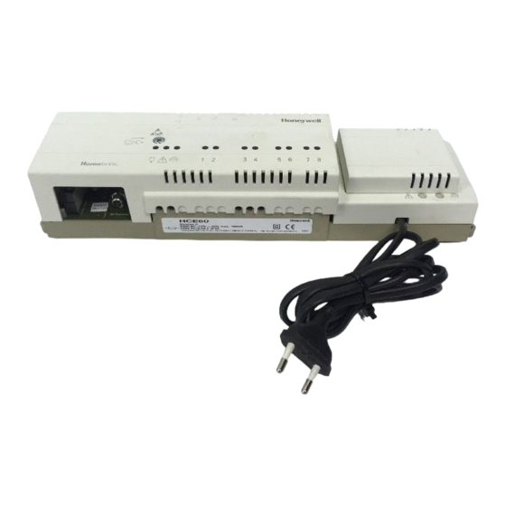
Technical terms are explained in the glossary (Page 45). They are identified in the text by an *. Application The storey controller HCE 60 receives information on the temperature of the room from the setpoint adjusters* and the Hometronic Man- ager. Using this information, the storey controller regulates the boiler feedback*, the pump relay*, and the thermal actuators* (see Page 48, Hometronic heating components). -
Page 6: Installation Procedure
Overview Installation procedure Classifying zones and actuators • Determine which heating circuits* are controlled by the storey controller. Installation • Install Hometronic components. Configuration and electrical connection • Set the storey controller to the actuator type, attach cables to the respective connections and connect components together. -
Page 7: Creating A Zoning Plan
Damage caused by equipment from other manufac- turers! The storey controller was designed for use with com- Caution ponents from Honeywell only! Use only H 200 BG (closed without current) or H 200 BO (open ► without current)-type actuators. Group actuators (by type and location) which are managed by the ►... -
Page 8: Filling Out Zoning Plan
Creating a zoning plan For more than 8 temperature zones or 24 actuators: Determine the number of additional storey controllers required using ► the following table: Temperature zones (maximum) The example at the end of this section shows zone divisions with corresponding zoning plan. - Page 9 Example of zone divisions 1, 2 etc. = Zone A = Living room B = Dining room C = Kitchen D = Hall E = Bedroom F = WC G = Bathroom Creating a zoning plan...
- Page 10 Creating a zoning plan This example shows: • The living area is covered by 6 temperature zones. The additional module HCS 60 is required for this partitioning. • A total of 8 actuators are controlled by the storey controller. Up to 8 temperature zones can be controlled by the additional module HCS 60.
- Page 11 The division yields the following zoning plan: Temperature Actuator zone (type, location) Heating loop 1 (living room) Zone 1 Heating loop 2 (living room) Heating loop 3 (living room) Zone 2 Heating loop 1 (dining room) Zone 3 Heating loop 1 (kitchen) Zone 4 Heating loop 1...
-
Page 12: Installation
Installation Installation The storey controller has a wireless receiver whose function is impaired by metal objects or wireless de- vices. Caution When selecting the operating site ensure that there is ► sufficient distance to metallic objects and radio de- vices. Select another installation site if the wireless interfer- ►... -
Page 13: Wall Installation
Wall installation Four 4.2 mm holes for installation are located on the storey controller. Dimensions of storey controller in mm Note the 60 mm installation height of the storey controller! If the storey controller is installed at a severe angle, the trans- former must be on top to allow for ventilation. -
Page 14: Din Rail Installation
Installation DIN rail installation Place housing on the DIN ► rail from below (1). Press housing upward and ► snap into place (2). Installing Hometronic components Install components as described in the accompanying installation ► instructions. -
Page 15: Configuration And Electrical Connection
Configuration and electrical connection Danger to life through electric shock! Live electrical contacts (actuator outputs, mains fuse Danger and transformer) lie open while the device is being cabled. Touching a live contact causes critical injuries. Work may only be carried out by authorized special- ►... -
Page 16: Opening Housing
Configuration and electrical connection Opening housing Loosen the screw on the ► front (1). Push both snap locks in- ► ward (2). Remove the housing cover ► from above (3). Plugging in the expansion module (optional) The expansion module HCS 60 expands the number of possible temperature zones per storey controller from 5 to 8. - Page 17 Setting actuator Only one type of actuator can be connected to a storey con- troller at a time. If actuators which are open with current and actuators which are closed with current are to be used, 2 storey controllers with the respective suitable controller are required.
-
Page 18: Cabling Connections
Opens the heating circuit if power is present at its control input. not present at its control input. Connection between sto- rey contr. HCE 60 and ... Setpoint adjuster HCW 23* 100 m Setpoint adjuster HCW 23* 100 m Setpoint adjuster HCW 23* 100 m... - Page 19 Use only cables with wire diameters up to 1.5 mm ommend the cable type JE-Y(St)Y 2×2×0.8. Use the accom- panying connector types and cables of sufficient length. 1. Connector (1 to 12) 2. Connections for expan- sion module HCS 60 3.
- Page 20 Configuration and electrical connection Connecting actuators Danger to life through electric shock! Live electrical contacts (actuator outputs, mains fuse Danger and transformer) lie open while the device is being cabled. Touching a live contact causes critical injuries. All work may only be carried out by authorized spe- ►...
- Page 21 Insert connector of actuator ► connection cables into the sockets of the respective zones. Squeeze the cables into the ► stress relief clamp. Break out the openings for the ► cables on the housing using a diagonal cutter. Configuration and electrical connection...
- Page 22 Configuration and electrical connection Connecting setpoint adjuster HCW 23 The setpoint adjuster HCW 23 is given fixed assignment via the zone wiring. Alternatively, a switchover relay can be connected. If the remote controller HCW 23 is removed, the assignment has to be removed as well. Refer to "Canceling assignment" on Page 38.
- Page 23 Connect the inputs in accordance with the accompanying instruc- ► tions. (Ground input on terminal 10 and temperature input on termi- nal 5 of the HCE 60.) With controller MCR 40, the temperature and ground inputs are lo- cated at the following terminals:...
- Page 24 Configuration and electrical connection With controller ZG 252 N, the temperature and ground inputs are located at the following terminals: Depending on the design, the temperature selector and ground inputs are found on different terminals of the controller MCR 200. Boiler feedback If control cables for heating (“boiler regression”) and for the pump relay are available:...
- Page 25 Connections of storey controller and pump relay Storey controller 1 Storey controller 2 Storey controller n Configuration and electrical connection HREL 1 RC PR RC PR RC PR...
- Page 26 Configuration and electrical connection Inserting connectors Insert connectors into the ► connector strip of the storey controller. Insert connector of antenna ► cable into the antenna socket of the storey controller.
- Page 27 Installing antenna An antenna must be connected to each storey controller! Take the antenna function into account when selecting the operating site: Antenna (1) must be ► installed outside metal housings (e.g. switch cabinets (4)). Do not lengthen antenna ► cable.
-
Page 28: Start-Up
Start-up Start-up During start-up, setpoint adjusters – and the time program of the wireless setpoint adjuster HCU 30 if applicable – are assigned to the temperature zones of the storey controller. A room name is defined for each temperature zone at the Hometronic Manager. Preparing for start-up Starting up setpoint adjuster HCW 22 Set adjustment dial to posi-... - Page 29 Insert 2 mignon batteries of ► type LR06, 1.5 V. Ensure that the polarity is ► correct. 1. Send button (required for start-up) Starting up storey controller Plug in power plug. ► The mains voltage LED Starting up setpoint adjuster HCU 30 See instructions of setpoint adjuster HCU 30.
-
Page 30: Led Indicators On Storey Controller
Start-up LED indicators on storey controller The LEDs on the storey controller indicate the operating mode of the storey controller and the installed temperature zones. Meaning of the 3 left-hand LEDs: Illumi- (green) nating Normal mode Illumi- Group (red) nating fault Flashing Fault display Illumi-... -
Page 31: Operating Modes Of Storey Controller
Operating modes of storey controller Normal mode In normal mode, LEDs 1 through 8 provide information on the posi- tion of the actuators: Green Fault mode In fault mode, the status displays provide information on a fault in the individual temperature zones. Refer to section "Displaying faults"... -
Page 32: Buttons
• Installation button Pressing the Installation but- ton switches the storey con- troller to installation mode or to the device display. Cooling function If the HCE 60 is used as a cooling regulator, this function must be activated during installation. - Page 33 Activating cooling function Press Fault button ► The storey controller switches to the fault display. The flashes red while pressing and then illuminates. The device display shows whether heating or heating/cooling is activated: LED flashing LED illuminating constantly Heating active Change setting if necessary: Press the Installation button ►...
-
Page 34: Assigning Zones And Issuing Room Names
Assigning zones and issuing room names Assigning zones and issuing room names The following section describes how a setpoint adjuster is assigned to a temperature zone and how a room name is then assigned to this zone. The procedure is identical for both device types. A temperature zone can only be assigned one setpoint ad- juster. - Page 35 Find the zoning plan. ► Press and hold Installation ► button on storey controller for at least 2 seconds. LED illuminates. The LED of zone 1 flashes red. The storey controller is in in- stallation mode and waits for the signal from the setpoint adjuster.
-
Page 36: Example: Assigning Room Name Living To Zone
Assigning zones and issuing room names Example: Assigning room name LIVING to zone 1 Press the installation button ► The LED of the selected zone flashes green. The storey controller waits for a signal from the Hometronic Manager. The Hometronic Manager is in auto- matic mode. - Page 37 Press the Input button. ► The following text is displayed: Select the "Settings" submenu and ► press the Input button. The following text is displayed: Select the "Installation" submenu ► and press the Input button. The following text is displayed: Select the "Heating"...
-
Page 38: Assigning Wireless Setpoint Adjuster Hcu 30 To A Temperature Zone
Assigning zones and issuing room names The LED on the storey controller in zone 1 illuminates green. The name "Living" has been assigned to temperature zone 1. Enter room name in zoning plan. ► Repeat these steps until a room name is assigned to all temperature ►... -
Page 39: Assigning Setpoint Adjusters Of Type Hcw 23 To A Zone
Assigning setpoint adjusters of type HCW 23 to a zone Setpoint adjusters of type HCW 23 have a fixed allocation to zones 1 and 2 due to their wiring. If the remote controller HCW 23 is removed, the assignment has to be removed as well. "Refer to "Canceling assignment" on Page 38. -
Page 40: Canceling Assignment
Assigning zones and issuing room names Press Installation button ► The LED of zone 1 flashes green. Assign room names for heating. ► Press Installation button ► The LED of zone 1 flashes green/orange. Assign room names for cooling. ► Repeat these steps until 2 room names are assigned to all tem- ►... -
Page 41: Deleting Assignment Of A Room Name At The Hometronic Manager
Canceling assignment of the room name or time program to the temperature zone Press the Installation button ► which the time program or room name is assigned, flashes green. Press Fault button ► out. The assignment of the room name or the time program to the tem- perature zone is canceled. -
Page 42: Saving Settings On Hometronic Manager
Assigning zones and issuing room names Select the "Heating" submenu and ► press the Input button. A list of the assigned room names (temperature zones) appears in the display: Select room name (in this case, ► Living) and press the Input button. The * symbol after the room name disappears: The assignment is deleted and can be reassigned. -
Page 43: Checking Wireless Transmission
No device installed Setpoint adjuster is installed Green Hometronic Manager resp. wireless setpoint adjuster HCU 30 are installed Orange Hometronic Manager and setpoint adjuster are installed If heating/cooling is activated, the following information can be called up: Press Installation button ►... -
Page 44: Checking Assignment Of Room Names
Assigning zones and issuing room names Checking assignment of room names Change setpoint temperature at Hometronic Manager (see instruc- ► tions of Hometronic Manager) LEDs 1 through 8 of the assigned zone flash up to three times. The assignment is correct. The storey controller exits the device display after approx. -
Page 45: Completing Start-Up
The colors of LEDs 1 through 8 now provide information on a fault in the temperature zones: No fault Cable break / no connection to setpoint adjuster Green No connection to Hometronic Manager resp. wireless setpoint adjuster HCU 30 Orange No connection to setpoint adjuster and Hometronic Man- ager The storey controller exits the fault display after approx. -
Page 46: Resetting Storey Controller To State Of Delivery
Assigning zones and issuing room names Resetting storey controller to state of delivery All current assignments are lost if the storey controller is reset to the state of delivery. The storey controller retains its con- figuration after a power failure. Pull out the connector of the storey controller. -
Page 47: Appendix
Appendix Glossary Boiler feedback Hometronic controls the heating boiler via an analog control de- vice of Honeywell. Heating circuit Area controlled by an actuator. Hometronic Home automation system from Honeywell. Hometronic Manager Central operating device of the Hometronic System. Room temperature sensor... -
Page 48: Help With Problems
Appendix Help with problems Problem does not illuminate when power plug is plugged in. LEDs 1 through 8 of the zones do not illuminate red continu- ously during start-up. LEDs 1 through 8 of the zones do not illuminate green con- tinuously during start- Not all rooms are warmed/cooled. - Page 49 Problem A room name cannot be installed at the Hometronic Manager. LED illumi- nates after start-up. Room controlled incorrectly. Cause/Solution An "*" is already present next to the room in the "Installation" menu. The room name was already issued. Uninstall room name. ►...
- Page 50 Appendix...
-
Page 51: Overview Of Hometronic Heating Components
Central operating unit of the house-automation system Setpoint adjuster HCW 23 (wired) Regulates setpoint temperature for each temperature zone via adjustment dial Storey controller HCE 60 Controls actuators of floor heaters/radiators; communicates with setpoint adjusters and room temperature sensors G Antenna... -
Page 52: Zoning Plan
Appendix Zoning plan Zone Actuator (type, location) * Cooling optional Setpoint adjuster (location) Room name Heating *Cooling Heating *Cooling Heating *Cooling Heating *Cooling Heating *Cooling... - Page 53 Distribution limitation • max. 5 (8) zones per storey controller • max. 3 connections per zone • max. 24 actuators per storey controller • only one type of thermal actuator per storey controller (normally open or normally closed) • either heating loops or radiators for each storey controller (floor heating) •...
-
Page 54: Notes
Notes Notes... - Page 56 Honeywell AG Böblinger Straße 17 D – 71101 Schönaich Tel. 01801 / 466390 The right is reserved to make This company is certificated to modifications This document is definitive for the enclosed product and replaces all previous publi- cations. No. 7157521...
Need help?
Do you have a question about the HCE 60 and is the answer not in the manual?
Questions and answers