Table of Contents
Advertisement
Advertisement
Table of Contents

Subscribe to Our Youtube Channel
Related Manuals for Galaxy Audio Any Spot Traveler AS-TV10


Summary of Contents for Galaxy Audio Any Spot Traveler AS-TV10
-
Page 2: Table Of Contents
Contents Introduction.....................1 Before using theTV10, TV8, TV5i & TV5X............1 TV10 Front & Rear panel configuration.............2 TV10 Master Control Panel................3 AS-TV8 Series Rear Panel Configuration............4 AS-TV8 & TV10 Series Description of Functions ........5-11 Power Supply/Charger..................5, 6 Power Switch....................5, 6 AS-TV8 Master Control..................5, 6 Digital Echo System................7 Audio Link Transmitter...................7, 8 Wireless Mic/Audio Link Receiver ..............8... -
Page 3: Introduction
Operating Manual for AS-TV10/TV8/TV5i/TV5X Series **Please visit www.galaxyaudio.com for the latest updates** Introduction Thank you for purchasing the TV10/TV8/TV5i/TV5X series wireless portable sound systems. These units feature an “all in one” design that allows them to be configured with a variety of different function modules to suit your specific needs. With rich, full sound and plenty of power, the TV10/TV8 series is ideally suited to cover large areas. -
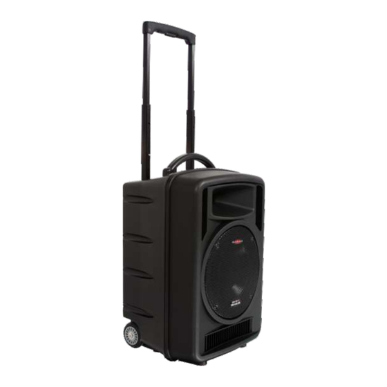
Page 4: Tv10 Front & Rear Panel Configuration
AS-TV10 Front & Rear Panel Configuration Front Side 1. Retractable Handle 2. Handle 3. Horn Tweeter 4. Speaker Grille 5. Woofer 6. Port 7. Wheels Rear Side 1. Retractable Handle 2. Optional Wireless Receivers 3. Optional CD/MP3 Player 4. Main Power Switch and Charging Indicator (Optional Transmitter module) 5. -
Page 5: Tv10 Master Control Panel
TV10 Master Control Panel 1. TREBLE control with center detent 2. BASS control with center detent 3. LINE IN volume control 4. AUX IN volume control 5. MIC2 volume control 6. MIC1 volume control 7. MASTER control for overall system volume 8. -
Page 6: As-Tv8 Series Rear Panel Configuration
AS-TV8 Series Rear Panel Configuration AS-TV8CT2 (Part# for unit shown with options) 1. Optional Receiver Modules 2. Optional MEDIA Player 3. Audio Link Transmitter 4. Power Switch 5. Mixer 6. Speaker Out 7. In/Out Jacks 8. Power Supply/Charging Input... -
Page 7: As-Tv8 & Tv10 Series Description Of Functions
Description of Functions for AS-TV8 & TV10 A. Power Supply/Charging Input 1. AC Power Cable connector 2. Batteries (behind cover) 3. Battery cover B. Power Switch and Charge Indicator for AS-TV8 & TV10 1. Power LED 2. Charging indicator 3. Power On/Off switch C. -
Page 8: Power Supply/Charger
Operation of TV8 & TV10 Portable Sound System A. Power Supply/Charger (see page 5) 1. There is a universal AC switching power supply/charger built into the system that will operate on voltages of 100~240V,50/60Hz. Verify that the voltage to which you are connecting is in that range and then connect the AC power cord from the AC IN (A1) to the wall outlet. -
Page 9: Digital Echo System
D. Digital Echo System (AS-TVEC) (for AS-TV8) 1. Master echo volume control 5. Wired mic 2 volume control 2. Delay repeat control 6. Wired mic 1-1/4" input jack 3. Delay time control 7. Wired mic 2-1/4" input jack 4. Wired mic 1 volume control 1. -
Page 10: Wireless Mic/Audio Link Receiver
5. When transmitting signal, the TX indicator (E-2) will light Green to show the transmitting condition. The AF Level indicator lights Yellow (E-3) to show a low audio level and lights Red (E-4) to show high audio level. 6. Set up the receiving Traveler according to the procedure outlined in: section ( ) F page 12. -
Page 11: Bluetooth Receiver Module
G. Bluetooth Receiver Module (TV-RECBT for TV8/TV10) (TV5-RECBT for TV5i & TV5X) 1. PWR - Power indicator 2. LINK - Bluetooth connectivity indicator 3. AF - Audio Frequency indicator 4. On/Off/Volume control knob 1. Turn the knob clockwise to switch on the Bluetooth module. Set a mid-range volume level to begin. -
Page 12: Rm-Cd Cd/Mp3/Sd/Usb Player
Optional Modules for TV10/TV8 10 11 12 13 14 15 16 1. USB Connector 9. Shuffle and execute button 2. Power Switch 10. Repeat: Repeat play mode 3. LCD display 11. Previous Folder 4. Mute 12. Next Folder 5. Program Button 13. -
Page 14: Tv5I Front & Rear Panel
TV5i Front and Rear Panel Configuration TV5iM1K9 (Part# for unit shown with options) 5. Controls, Battery Meter, Mic in 1. Tweeter (1") 6. Power Switch 2. Neodymium Driver (5") 3. Optional UHF Receiver 7. DC Input 4. Optional Digital Media Player 8. -
Page 15: Tv5I Bluetooth Connection
I. Rear Panel of TV5i 1. DC Power Input 2. Power Switch 3. Power LED 4. Master 5. Treble 6. Bass 7. Battery meter 8. Voice priority: when activated, Priority LED (6) will light. 9. Voice priority indicator 10. Bluetooth Button (if equipped) 11. -
Page 16: Tv5Mp3 Optional Media Player
TV5MP3 Optional Media Player for TV5i & TV5X remote control 8. Repeat / Folder select 1. LCD display 9. Power 2. Previous track / volume 10. Volume down down (works during playback) (MUTE when in minimum level) 3. Next track / volume up 11. -
Page 17: Wireless Microphone Receiver Option Tv5-Rec For Tv5I & Tv5X
K. Wireless Microphone Receiver Option (TV5-REC) For TV5i and TV5X 1. LCD window 2. Antenna A and B indicator 3. RF signal indicator 4. AF signal indicator 5. Synchronization button 6. Channel up/down adjustment 7. Receiver power on/off control and volume adjustment Operation: Turn receiver power on/off control (K7) clockwise until a click occurs. -
Page 18: Tv5X Panel Configuration
TV5X Panel Configuration XM1FK9 (Part# for unit shown with options) 1. Controls, Battery Life, Mic in 5. LED indicator 2. Digital Media Player 6. Drop in Hand Held Charger 3. Wireless Receiver 7. Strap Attachment Point 4. Battery Door K. Control Panel for TV5X 1. -
Page 20: Wireless Hand Held & Body Pack Transmitters Tvhh Microphone Description & Functions
Description of Functions for Hand held Microphone AS-TVHH/TVHHC Front Panel Wind Screen: Protects cartridge with Pop Filter. Main Body: Contains Wireless Transmitter PCB. SET button for Rear Panel channel settings Volume Control: Three level settings, including mute, LOW and HI. LCD panel: Channel and frequency display. - Page 21 Operation of Hand Held Microphone AS-TVHH/TVHHC A. Battery Installation Steps: 1. Turn off the microphone before inserting batteries. 2. Press in the latch to release the lower housing and slide it off. 3. Press in the latch to release the battery cover and slide it down. 4.
-
Page 22: Charging Status
E. LCD Indications: :Three bars means batteries are fully charged. :One bar indicates low batteries. Replace or recharge the batteries. :No bars showing indicates batteries are exhausted and after flashing three times the power will automatically shut off. F. Battery Charging Steps: 1. -
Page 23: Tvh2 Microphone Description & Functions
c. Check if the distance between the transmitter and the receiver is too great. d. Check if the transmitter or the receiver is too close to any large metal objects. 5. Interference and signal Disturbance. a. Make sure there are no other wireless systems operating on the same frequency in the same area. - Page 24 Operation of Hand held Microphone AS-TVH2 A. Battery Installation Steps: 1. Turn off the microphone before inserting batteries. 2. Press in the latch to release the battery cover and slide it down. 3. Insert 2 disposable batteries of 1.5V type or 2 rechargeable batteries of 1.2V type.
-
Page 25: As-Tvbpt Body Pack Transmitter Description & Functions
3. With the switch in the Push position the microphone is muted until you press and hold the mute button. 4. In either position, when the mute switch is green the microphones is on, when the mute button is red the microphone is muted. F. - Page 26 Operation of AS-TVBPT Transmitter A. Switch-On Steps: 1. Press the power switch and hold for about two seconds until the LED turns to Blue and is displayed in the LCD. The LCD will then automatically display the selected channel. B: Volume adjust Press the + button to increase press the –...
-
Page 27: As-Tvbpr Body Pack Receiver Description & Functions
Description of Functions for Body Pack Receiver AS-TVBPR 1. MUTE switch 7. Line out 2. Channel 8. Strap attachment point 3. LCD 9. DC charging input 4. Power / Volume switch 10. Strap attachment point 5. Audio out 11. Belt clip 6. -
Page 28: As-Tvmbp Body Pack Transmitter Description & Functions
C: Mute 1. Press the mute button, it will turn red to indicate mute. D. Channel/Frequency Settings (with power on): 1. Press the + button to display a higher numbered channel. 2. Press the - button to display a lower numbered channel. 3. - Page 29 Operation of AS-TVMBP Body Pack Transmitter A. Battery Installation: 1. Switch the transmitter off before inserting batteries. 2. Slide the battery cover off. 3. Insert 2 disposable batteries (1.5V AA) or 2 rechargeable batteries (1.2V AA). 4. Observe correct polarity when inserting batteries. 5.
- Page 30 E. Battery Charging Steps: 1. Insure that the batteries are the rechargeable type. 2. Switch Power to OFF position. 3. Insert AS-TVMBP into its own intelligent charger stand (AS-DCTVMBP). 4. Batteries will recharge automatically. 5. For more details of charger stand please refer to AS-DCTVMBP user guide. F.
-
Page 31: Maintenance
Maintenance Avoid Excessive Heat Don't leave transmitter or receiver in hot sun, on a radiator, or near other sources of high temperature. Avoid Rough Handling The transmitter and receiver may be damaged if dropped. Storage Before storage, fully charge the batteries in both transmitters and receivers. If possible, recharge once a month during storage and again before first use. -
Page 32: As-Txrm Stationary Transmitter
AS-TXRM Stationary Transmitter The AS-TXRM is a stand alone version of our AS-TVTX Audio Link Transmitter module. The module is housed in a standard half-rack sized enclosure, and includes a variety of inputs and outputs as well as mixing controls. The AS-TXRM is great for transmitting the entire mix from a mixing console to one or more Traveler speakers equipped with wireless receivers. -
Page 33: Setup And Operation Of Txrm
Setup and Operation of AS-TXRM Starting with both the main power switch off (1) and the transmitter (8) power switch off, plug the included power supply into the DC In jack (18), and then plug the other end into an AC outlet. Connect the supplied antenna to the Antenna Jack (11). -
Page 34: Specifications
CAUTION Danger of explosion if the battery is incorrectly installed. Replace only with the same or the equivalent type. S p e c i f i c a t i o n s TV10 Portable Amplifier Speaker 92 dB, 1Watt @ 1 M Sensitivity Maximum SPL 112 dB... -
Page 35: As-Tv8 Specifications
CAUTION Danger of explosion if the battery is incorrectly installed. Replace only with the same or the equivalent type. S p e c i f i c a t i o n s Portable Amplifier Speaker 92 dB, 1Watt @ 1 M Sensitivity 109 dB Maximum SPL... -
Page 36: Tv5I Specifications
S p e c i f i c a t i o n s TV5i Portable Amplifier Speaker 88 dB, 1Watt @ 1 M Sensitivity 104 dB Maximum SPL 70 Hz ~ 16 kHz (audio) Frequency response Speakers 5" Woofer, 1" Tweeter AS-TVREC x 2 diversity (optional) Receiver module 40 W (RMS) @ 4ohm... -
Page 37: Tv5X Specifications
S p e c i f i c a t i o n s TV5X Portable Amplifier Speaker 88 dB, 1Watt @ 1 M Sensitivity 104 dB Maximum SPL 70 Hz ~ 16 kHz (audio) Frequency response Speakers 5" Neolite Speaker AS-TVREC x 2 diversity (optional) Receiver module 40 W (RMS) @ 4ohm... -
Page 38: As-Tvrec Wireless Receiver Module
Wireless Mic/Audio link Receiver Module (AS-TVREC) Oscillation type PLL synthesized control OSC Adjustable frequency Pre-programmed max. 96 switchable channels Max. 12 MHz Switching bandwidth -10 ºC ~ 50 ºC Ambient temperature 50 kHz, with level limiting Maximum deviation Dynamic range 110 dB T. -
Page 39: As-Tvtx & Txrm Audio Link Transmitter Module
Wireless Mic/Audio link Receiver (AS-TVREC) (continued) Antenna Built-in or external Dimensions ( L x W x H ) 5.25" x 3.46" x 1.45" (133 x 88 x 37 mm) Weight 3.88 oz. (110 g) Audio Link Transmitter Module (AS-TVTX also used in TXRM) 10mW RF output Spurious emission... -
Page 40: As-Tvh2 Handheld Microphones
Handheld Microphone (AS-TVHH) (continued) SET, UP, DOWN keys Channel select Hi/Low/Mute switch AF controls 1.2 V (Ni-MH 1300 mAh) * 2 AA type rechargeable battery Batter y 1.5V * 2 AA Alkaline disposable Batter y life Ni-MH rechargeable 11 hours typical Batter y life Alkaline disposable 14 hours typical Antenna... -
Page 41: As-Tvmbp Body Pack Transmitter
Bodypack Transmitter (AS-TVMBP) Microphone Type Headset or Lavalier RF output 10mW Spurious emission Less than 250 nW LCD indicator displays channel or frequency, Display status battery life SET, UP, DOWN keys Channel select Mute switch, Hi/Mid/Low switch AF controls Audio input Mic in, Aux in 1.2 V (Ni-MH 1300 mAh) * 2 AA type rechargeable battery Batter y... -
Page 42: Bodypack Transmitter
Bodypack Transmitter (AS-TVBPT) (continued) Batter y Rechargeable Lithium Battery Batter y life 12 - 16 hours typical Dimensions ( D x W x H ) 3.46" x 2.04" x 1.33" (88 x 52 x 34mm) Weight with batter y 2.64oz. (75 kgs) Digital Media Player (TV5MP3) Frequency Response... - Page 44 V20140408...
Need help?
Do you have a question about the Any Spot Traveler AS-TV10 and is the answer not in the manual?
Questions and answers