Table of Contents
Advertisement
Quick Links
Advertisement
Table of Contents

Related Manuals for Galaxy Audio Any Spot Traveler AS-TV8


Summary of Contents for Galaxy Audio Any Spot Traveler AS-TV8
-
Page 2: Table Of Contents
Introduction.....................1 Before using theTV10, TV8 or TV5............2 TV10 Front & Rear panel configuration..........3 TV10 Master Control Panel..............4 Optional Modules for TV10/TV8............5 Front Panel Configuration of AS-TV8 Series..........6 Rear Panel Configuration of AS-TV8 Series .........7 Description of Functions of AS-TV8 Series........8-10 Operation of the AS-TV8...............11 Power Supply/Charger................11 Power Switch..................11... - Page 3 Thank you for purchasing the TV10/TV8/TV5 series wireless portable sound systems. These units feature an “all in one” design that allows them to be configured with a variety of different function modules to suit your specific needs. With rich, full sound and plenty of power, the TV10/TV8 series is ideally suited to cover large areas.
- Page 4 The TV10, TV8 and TV5 use a universal AC switching power supply/charger that will operate on voltages of 100~240V,50/60Hz. The TV10, TV8 power supplies are internal, while the TV5's is external. Verify that the voltage to which you are connecting is in this range and then connect the AC power cord from the Traveler to the wall outlet.
- Page 6 TREBLE control with center detent BASS control with center detent c. LINE IN volume control d. AUX IN volume control e. MIC2 volume control f. MIC1 volume control g. MASTER control for overall system volume h. VOICE PRIORITY button to activate or end the microphone priority function e.g.
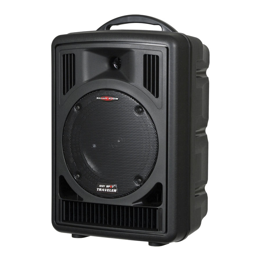
- Page 8 Handle 1" Horn 8" Woofer Speaker Grille Heat Sink...
-
Page 9: Power Supply/Charger
Receiver Modules CD/CMP Player Audio Link Transmitter Power Switch Mixer Speaker Out In/Out Jacks Power Supply/ Charging Input... - Page 11 F. Wireless Microphone/Audio Link Receiver (AS-TVREC) (for AS-TV5, TV8/TV10) 1. LCD display 2. A/B diversity indicator 3. RF indicator 4. AF level indicator 5. Channel Set 6. Channel selector 7. Power switch & mic. volume G. Anti-Shock CD/CMP Player (RM-CD) (for TV8/TV10) 1.
- Page 12 H1. Digital Echo System (AS-TVEC) (for AS-TV8) 1. Master echo volume control 2. Delay repeat control 3. Delay time control 4. Wired mic 1 volume control 5. Wired mic 2 volume control 6. Wired mic 1-1/4" input jack 7. Wired mic 2-1/4" input jack H2.
- Page 13 Operation of TV8 Portable Sound System A. Power Supply/Charger (see page 8) 1. There is a universal AC switching power supply/charger built into the system that will operate on voltages of 100~240V,50/60Hz. Verify that the voltage to which you are connecting is in that range and then connect the AC power cord from the AC IN (A1) to the wall outlet.
-
Page 14: Wireless Mic/Audio Link Receiver
F. Wireless Mic/Audio link Receiver (AS-TVREC) (see page 9) This system may include one or two receivers with selectable PLL 96 channel operation. These modules receive signals from wireless Mics or from another Traveler equiped with an Audio Link Transmitter. 1. - Page 15 H1. Digital Echo System (AS-TVEC) (see page 10) 1. Turn the Echo Control (H1-1) clockwise to turn on the echo system. Then use this control to adjust the level of echo in the mix. Echo will be applied to all 3 mic inputs.
-
Page 17: Operation Of Tv5 And Optional Modules
Operation of TV5 and Optional Modules (See Page 14) For AC power operation or Charging: Connect the DC end of the Power Supply/Charger cable to the DC In Jack (I1). Then connect the other end (AC plug) to the AC wall outlet. See page 2 for more information on Charging, Power Switch, and LED Indicators. - Page 18 Wind Screen: Protects cartridge with Pop Filter. Main Body: Contains Wireless Transmitter PCB. SET button for channel settings LCD panel: Channel and frequency display. UP and DOWN buttons: For Channel select and Frequency display. LED: Power status Power Switch: Charging Input: Remove lower housing to access.
- Page 19 Volume Control: Three level settings, including mute, LOW and HI. MUTE Pushing point: Slide the battery cover down by pressing here. Battery Cover Lower Housing: Remove to slide battery cover off or to connect charger...
-
Page 20: Operation Of Handheld Microphone
Operation of Handheld Microphone AS-TVHH/TVHHC A. Battery Installation Steps: 1. Turn off the microphone before inserting batteries. 2. Press in the latch to release the lower housing and slide it off. 3. Press in the latch to release the battery cover and slide it down. 4. - Page 21 4. Press the Down button to display a lower numbered channel. 5. Press the SET button to activate the selected channel. E. LCD Indications: :Three bars means batteries are fully charged. :One bar indicates low batteries. Replace or recharge the batteries.
- Page 22 G. Troubleshooting: 1. LED doesn't light when power switch is pressed to turn on mic. a. Make sure that the batteries are not discharged. b. Make sure that the batteries are installed correctly. 2. LCD shows when power switch is pressed to turn mic off. Press the SET, UP and DOWN buttons at the same time in order to turn the microphone off automatically.
-
Page 23: Description Of Functions For Body Pack Transmitter
Description of Functions for Body Pack Transmitter AS-TVMBP 1. Mini XLR Mic input jack (TA3M) 2. Power switch 3. Mute button 4. Antenna 5. Power light 6. Charging Jack 7. LCD light 8. Set button 9. Channel select button 10. Sensitivity control 11. -
Page 24: Operation Of Bodypack Transmitter
Operation of Bodypack Transmitter A. Battery Installation: 1. Switch the transmitter off before inserting batteries. 2. Slide the battery cover off. 3. Insert 2 disposable batteries (1.5V AA) or 2 rechargeable batteries (1.2V AA). 4. Observe correct polarity when inserting batteries. 5. - Page 25 E. Battery Charging Steps: 1. Insure that the batteries are the rechargeable type. 2. Switch Power to OFF position. 3. Insert AS-TVMBP into its own intelligent charger stand (AS-DCTVMBP). 4. Batteries will recharge automatically. 5. For more details of charger stand please refer to AS- DCTVMBP user guide.
-
Page 26: Maintenance
Maintenance Avoid Excessive Heat Don't leave transmitter or receiver in hot sun, on a radiator, or near other sources of high temperature. Avoid Rough Handling The transmitter and receiver may be damaged if dropped. Storage Before storage, fully charge the batteries in both transmitters and receivers. If possible, recharge once a month during storage and again before first use. -
Page 27: As-Txrm Stationary Transmitter
AS-TXRM Stationary Transmitter The AS-TXRM is a stand alone version of our AS-TVTX Audio Link Transmitter module. The module is housed in a standard half-rack sized enclosure, and includes a variety of inputs and outputs as well as mixing controls. The TXRM is great for transmitting the entire mix from a mixing console to one or more Traveler speakers equipped with wireless receivers. -
Page 28: Setup And Operation Of Txrm
Setup and Operation of TXRM (See Page 24) Starting with both the main power switch off (1) and the transmitter (8) power switch off, plug the included power supply into the DC In jack (18), and then plug the other end into an AC outlet. Connect the supplied antenna to the Antenna Jack (11). - Page 29 CAUTION Danger of explosion if the batter y is incorrectly installed. Replace only with the same or the equivalent type. 92 dB, 1Watt @ 1 M Sensitivity Maximum SPL 112 dB Frequency response 20 Hz ~ 20 kHz (audio) Speakers 10"...
- Page 30 CAUTION Danger of explosion if the batter y is incorrectly installed. Replace only with the same or the equivalent type. 92 dB, 1Watt @ 1 M Sensitivity Maximum SPL 112 dB Frequency response 70 Hz ~ 20 kHz (audio) Speakers 8"...
- Page 31 92 dB, 1Watt @ 1 M Sensitivity Maximum SPL 100 dB Frequency response Hz ~ kHz (audio) Speakers 5" Full Range Receiver module AS-TVREC x 2 diversity (optional) Output power 30 W RMS, 50 W MAX. Signal to noise ratio Optional Media Player DIGIMP5 (optional)
- Page 32 Oscillation type PLL synthesized control OSC Adjustable frequency Pre-programmed max. 96 switchable channels Switching bandwidth Max. 12 MHz -10 ºC ~ 50 ºC Ambient temperature 50 kHz, with level limiting Maximum deviation Dynamic range 110 dB T. H. D. Less than 0.5% Pre/De- emphasis 50 s µ...
- Page 33 Antenna Built-in or external Dimensions ( L x W x H ) 5.25" x 3.46" x 1.45" (133 x 88 x 37 mm) Weight 3.88 oz. (110 g) RF output 10mW Spurious emission Less than 250 nW Display status LCD indicator displays channel or frequency SET, UP, DOWN keys Channel select Antenna...
- Page 34 SET, UP, DOWN keys Channel select Hi/Low/Mute switch AF controls 1.2 V (Ni-MH 1300 mAh) * 2 AA type rechargeable battery Batter y 1.5V * 2 AA Alkaline disposable Batter y life Ni-MH rechargeable 11 hours typical Batter y life Alkaline disposable 14 hours typical Antenna Built-in Dimensions ( Dia x L )
- Page 35 5. Damage occurring during the shipment or delivery of any Galaxy Audio product to Galaxy Audio after initial delivery of the product to you. 6. Damage to any Galaxy Audio product which has been altered or on which the serial number has been effaced or removed.
Need help?
Do you have a question about the Any Spot Traveler AS-TV8 and is the answer not in the manual?
Questions and answers