Table of Contents
Advertisement
www.nordictrack.com
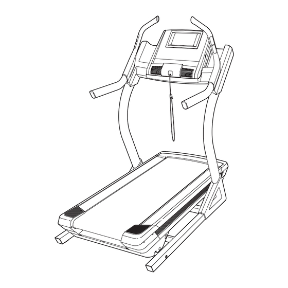
Model No. NTL19010.2
Serial No.
Write the serial number in the space
above for reference.
QUESTIONS?
If you have questions, or if parts
are damaged or missing, DO NOT
CONTACT THE STORE; please
contact Customer Care.
IMPORTANT: Please register this
product (see the limited warranty
on the back cover of this manual)
before contacting Customer Care.
CALL TOLL-FREE:
1-800-TO-BE-FIT
(1-800-862-3348)
Mon.–Fri. 6 a.m.–6 p.m. MT
Sat. 8 a.m.–4 p.m. MT
ON THE WEB:
www.nordictrackservice.com
CAUTION
Read all precautions and instruc-
tions in this manual before using
this equipment. Save this manual
for future reference.
Serial
Number
Decal
USER'S MANUAL
Advertisement
Table of Contents

Related Manuals for NordicTrack NTL19010.2


Summary of Contents for NordicTrack NTL19010.2
- Page 1 USER’S MANUAL Model No. NTL19010.2 Serial No. Write the serial number in the space above for reference. Serial Number Decal QUESTIONS? If you have questions, or if parts are damaged or missing, DO NOT CONTACT THE STORE; please contact Customer Care.
-
Page 2: Table Of Contents
TABLE OF CONTENTS WARNING DECAL PLACEMENT ............. . 2 IMPORTANT PRECAUTIONS . -
Page 3: Important Precautions
IMPORTANT PRECAUTIONS WARNING: To reduce the risk of serious injury, read all important precautions and in- structions in this manual and all warnings on your incline trainer before using your incline trainer. ICON assumes no responsibility for personal injury or property damage sustained by or through the use of this product. - Page 4 19. The heart rate monitor is not a medical 23. Inspect and properly tighten all parts of the device. Various factors, including the user’s incline trainer regularly. movement, may affect the accuracy of heart DANGER: rate readings. The heart rate monitor is in- Always unplug the power tended only as an exercise aid in determining cord immediately after use, before cleaning...
-
Page 5: Before You Begin
BEFORE YOU BEGIN Thank you for selecting the revolutionary reading this manual, please see the front cover of this NORDICTRACK INCLINE TRAINER X9i manual. To help us assist you, note the product model ® INTERACTIVE. The INCLINE TRAINER X9i number and serial number before contacting us. The INTERACTIVE offers a selection of features designed model number and the location of the serial number to make your workouts at home more enjoyable and... -
Page 6: Part Identification Chart
PART IDENTIFICATION CHART Use the drawings below to identify small parts used for assembly. The number in parentheses below each draw- ing is the key number of the part, from the PART LIST near the end of this manual. The number following the key number is the quantity used for assembly. -
Page 7: Assembly
ASSEMBLY • Assembly requires two persons. • To identify small parts, see page 6. • P lace all parts in a cleared area and remove the • A ssembly requires the following tools: packing materials. Do not dispose of the packing materials until you finish all assembly steps. the included hex keys • T he underside of the walking belt is coated with one Phillips screwdriver high-performance lubricant. - Page 8 2. Attach the Upright (77) to the Base (80) with two 3/8" x 5 1/2" Screws (5) and a 3/8" x 2 3/4" Screw (17) with three 3/8" Star Washers (8) as shown. Start all three Screws, and then tighten them. Be careful not to pinch the Upright Wire (not shown) in the Upright.
- Page 9 4. Have a second person hold the console assem- bly near the Uprights (77). Insert the console wire and the “R” pulse wire from the console assembly through the indicated tie. Connect the Upright Wire (78) to the console wire. See the inset drawing. The connectors should slide together easily and snap into place.
- Page 10 6. Tighten two #8 x 3/4" Screws (1) into the Console Base (87). Do not overtighten the Screws. Identify the Right Handrail Assembly (93). Hold the Right Handrail Assembly near the right Upright (77). Insert the pulse wire from the Right Handrail Assembly into the hole in the top of the Upright and pull it out of the end of the Upright.
- Page 11 8. Hold the Left Handrail Assembly (86) near the left Upright (77). Insert the pulse wire from the left handrail assembly into the hole in the top of the Upright and pull it out of the end of the Upright. Set the Left Handrail Assembly (86) onto the left Upright (77).
- Page 12 10. See page 14 and plug in the power cord. Next, see page 16 and turn on the power. Then, touch the 1 Step Incline button numbered 40 on the console. The Frame (58) will adjust to an incline of 40 percent. Then, turn off the incline trainer and unplug the power cord.
-
Page 13: The Chest Heart Rate Monitor
THE CHEST HEART RATE MONITOR HOW TO PUT ON THE HEART RATE MONITOR • D o not expose the heart rate monitor to direct sunlight for extended periods of time; do not expose The heart rate it to temperatures above 122° F (50° C) or below 14° monitor consists of F (-10°... -
Page 14: Operation And Adjustment
OPERATION AND ADJUSTMENT HOW TO CONNECT THE POWER CORD nominal 120-volt circuit capable of carrying 15 or more amps. To avoid overloading the circuit, do Use a Surge Suppressor not plug other electrical devices, except for low- power devices such as cell phone chargers, into Your treadmill, like other electronic equipment, can be the surge suppressor or into an outlet on the same circuit. - Page 15 CONSOLE DIAGRAM FEATURES OF THE CONSOLE As you exercise, the console will display instant ex- ercise feedback. You can also measure your heart The incline trainer console offers an impressive array rate using the handgrip heart rate monitor or the chest of features designed to make your workouts more ef- heart rate monitor.
- Page 16 HOW TO TURN ON THE POWER HOW TO USE THE TOUCH SCREEN IMPORTANT: If the incline trainer has been ex- The console features a tablet with a full-color touch posed to cold temperatures, allow it to warm to screen. The following information will help you become room temperature before you turn on the power.
- Page 17 HOW TO SET UP THE CONSOLE Next, enter a username and password and your e-mail address. Enter the activation code from Before using the incline trainer for the first time, set up the iFit Live flier that came with the incline trainer. the console.
- Page 18 HOW TO USE THE MANUAL MODE Note: The first time you adjust the incline, you must first calibrate the incline system (see step 4 on 1. Insert the key into the console. page 24). 5. Monitor your progress. See HOW TO TURN ON THE POWER on page 16.
- Page 19 rate will be shown. For the most accurate heart The displays at the top of the screen can show two rate reading, continue to hold the contacts for types of information. Touch each display until the display shows the desired information. about 15 seconds.
- Page 20 HOW TO USE AN ONBOARD WORKOUT If the speed or incline setting is too high or too low at any time during the workout, you can override 1. Insert the key into the console. the setting by pressing the Speed or Incline but- tons;...
- Page 21 HOW TO USE A SET-A-GOAL WORKOUT The workout will function in the same way as the manual mode (see pages 18 and 19). 1. Insert the key into the console. The workout will continue until you reach the goal See HOW TO TURN ON THE POWER on page that you set.
- Page 22 HOW TO USE AN IFIT LIVE WORKOUT Before some workouts will download, you must add them to your schedule on iFit.com. Note: To use an iFit Live workout, you must have ac- For more information about the iFit Live work- cess to a wireless network (see HOW TO USE THE outs, please see www.iFit.com.
- Page 23 HOW TO USE THE EQUIPMENT SETTINGS MODE reset position, and insert the key into the console. However, when you remove the key, the screen The console features an equipment settings mode will show a demo presentation. that allows you to select a language and the unit of measurement, to turn on and turn off the display demo To turn on or turn off the display demo mode, first mode, and to enable or disable the key.
- Page 24 HOW TO USE THE MAINTENANCE MODE USB drive. Safely remove the USB drive from your computer and plug it into the USB port on the side The console features a maintenance mode that al- of the console. The update should begin lows you to update the console firmware, calibrate the automatically.
- Page 25 HOW TO USE THE WIRELESS NETWORK MODE An information box will ask if you want to connect to the wireless network. Touch the Connect button The console features a wireless network mode that al- to connect to the network or touch the Cancel but- lows you to set up a wireless network connection.
- Page 26 HOW TO USE THE STEREO SOUND SYSTEM HOW TO USE THE INTERNET BROWSER To play music or audio books through the console’s Note: To use the browser, you must have access to speakers, you must connect your MP3 player, CD a wireless network including an 802.11b/n router with player, or other personal audio player to the console.
-
Page 27: How To Move The Incline Trainer
HOW TO MOVE THE INCLINE TRAINER Before moving the incline trainer, insert the key into the console, raise the incline to the maximum incline level, Console remove the key, and unplug the power cord. Due to the size and weight of the incline trainer, mov- Belly ing it requires two or three persons. -
Page 28: Troubleshooting
TROUBLESHOOTING Most incline trainer problems can be solved by fol- c. Remove the key from the console, and then lowing the simple steps below. Find the symptom reinsert it. that applies, and follow the steps listed. If further assistance is needed, see the front cover of this d. - Page 29 Locate the Reed Switch (55) and the Magnet (41) b. If the walking belt is overtightened, incline trainer on the left side of the Pulley (42). Turn the Pulley performance may decrease and the walking belt until the Magnet is aligned with the Reed Switch. may become damaged.
- Page 30 SYMPTOM: The walking belt is off-center or slips SYMPTOM: The iFit Live mode does not function when walked on correctly a. If the walking belt is off-center, first adjust the in- a. If the iFit Live mode is not functioning correctly, cline to 40 percent.
-
Page 31: Exercise Guidelines
EXERCISE GUIDELINES Burning Fat—To burn fat effectively, you must exer- WARNING: cise at a low intensity level for a sustained period of Before beginning this time. During the first few minutes of exercise, your or any exercise program, consult your physi- body uses carbohydrate calories for energy. -
Page 32: Suggested Stretches
SUGGESTED STRETCHES The correct form for several basic stretches is shown at the right. Move slowly as you stretch —never bounce. 1. Toe Touch Stretch Stand with your knees bent slightly and slowly bend forward from your hips. Allow your back and shoulders to relax as you reach down toward your toes as far as possible. -
Page 33: Part List
PART LIST Model No. NTL19010.2 R0212A Key No. Qty. Description Key No. Qty. Description #8 x 3/4" Screw Grommet #8 x 3/4" Tek Screw Belly Pan Cover Left Inside Cover Power Switch 5/16" x 2 1/2" Screw Belly Pan 3/8" x 5 1/2" Screw Reed Switch 3/8"... - Page 34 Key No. Qty. Description Key No. Qty. Description Console Crossbar Frame Bushing #8 x 1" Screw Computer Crossbar 1/4" Nut Console Clamp Leveling Feet 3/8" x 2 1/2" Screw – User’s Manual Left Outside Cover Note: Specifications are subject to change without notice. For information about ordering replacement parts, see the back cover of this manual.
-
Page 35: Exploded Drawing
EXPLODED DRAWING A Model No. NTL19010.2 R0212A... - Page 36 EXPLODED DRAWING B Model No. NTL19010.2 R0212A...
- Page 37 EXPLODED DRAWING C Model No. NTL19010.2 R0212A...
- Page 38 EXPLODED DRAWING D Model No. NTL19010.2 R0212A...
- Page 39 EXPLODED DRAWING E Model No. NTL19010.2 R0212A...
-
Page 40: Ordering Replacement Parts
ORDERING REPLACEMENT PARTS To order replacement parts, please see the front cover of this manual. To help us assist you, be prepared to provide the following information when contacting us: • the model number and serial number of the product (see the front cover of this manual) • the name of the product (see the front cover of this manual) • t he key number and description of the replacement part(s) (see the PART LIST and the EXPLODED DRAWING near the end of this manual) LIMITED WARRANTY IMPORTANT: You must register this product within 30 days of the purchase date to avoid added fees for service needed under warranty.
Need help?
Do you have a question about the NTL19010.2 and is the answer not in the manual?
Questions and answers