Table of Contents
Advertisement
www.nordictrack.com
Model No. NTL29016.0
Serial No.
Write the serial number in the space
above for reference.
ACTIVATE YOUR
WARRANTY
To register your product and
activate your warranty today, go
to www.nordictrackservice.com/
registration.
CUSTOMER CARE
For service at any time, go to
www.nordictrackservice.com.
Or call 1-800-TO-BE-FIT
(1-800-862-3348)
Mon.–Fri. 6 a.m.–6 p.m. MT
Sat. 8 a.m.–12 p.m. MT
Please do not contact the store.
CAUTION
Read all precautions and instruc-
tions in this manual before using
this equipment. Save this manual
for future reference.
Serial
Number
Decal
USER'S MANUAL
Advertisement
Table of Contents

Subscribe to Our Youtube Channel
Related Manuals for NordicTrack NTL29016.0


Summary of Contents for NordicTrack NTL29016.0
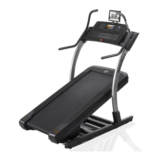
- Page 1 USER’S MANUAL Model No. NTL29016.0 Serial No. Write the serial number in the space above for reference. Serial Number Decal ACTIVATE YOUR WARRANTY To register your product and activate your warranty today, go to www.nordictrackservice.com/ registration. CUSTOMER CARE For service at any time, go to www.nordictrackservice.com.
-
Page 2: Table Of Contents
Apply the decal in the location shown. Note: The decals may not be shown at actual size. NORDICTRACK and IFIT are registered trademarks of ICON Health & Fitness, Inc. Google Maps is a trademark of Google Inc. The BLUETOOTH ®... -
Page 3: Important Precautions
14. To commercial, rental, or institutional setting. purchase a surge suppressor, see your local NORDICTRACK dealer, call the telephone 6. Keep the incline trainer indoors, away from number on the front cover of this manual, or moisture and dust. - Page 4 18. Read, understand, and test the emergency 25. Do not attempt to move the incline trainer stop procedure before using the incline until it is properly assembled. (See trainer. (See HOW TO TURN ON THE POWER ASSEMBLY on page 9, and HOW TO MOVE on page 17.) Always wear the clip while using THE INCLINE TRAINER on page 27.) You must the incline trainer.
- Page 6 STANDARD SERVICE PLANS...
-
Page 7: Before You Begin
BEFORE YOU BEGIN Thank you for selecting the revolutionary reading this manual, please see the front cover of this NORDICTRACK X22I INCLINE TRAINER. The X22I manual. To help us assist you, note the product model ® INCLINE TRAINER offers a selection of features number and serial number before contacting us. -
Page 8: Part Identification Chart
PART IDENTIFICATION CHART Use the drawings below to identify small parts used for assembly. The number in parentheses below each draw- ing is the key number of the part, from the PART LIST near the end of this manual. The number following the key number is the quantity used for assembly. -
Page 9: Assembly
ASSEMBLY • Assembly requires two persons. • To identify small parts, see page 8. • Place all parts in a cleared area and remove the • Assembly requires the following tools: packing materials. Do not dispose of the packing materials until you fi nish all assembly steps. the included hex keys •... - Page 10 2. Make sure that the power cord is unplugged. Remove the four 3/8" x 3 1/4" Screws (18) from the Base (74) (only one side is shown). Save the Screws. 3. Remove the four 3/8" x 2 3/4" Screws (22) from the Uprights (83).
- Page 11 4. Set the Uprights (83) on the Base (74). Make sure that the hole with the Upright Wire (75) is on the right side. Attach the right Upright (83) to the Base (74) with two of the 3/8" x 3 1/4" Screws (18) and two of the 3/8"...
- Page 12 6. Identify the Right Handrail (89). Hold the Right Handrail near the right side of the console assembly (C), and connect the two pulse wires (D). Next, set the Right Handrail (89) on the console assembly (C). Make sure that no wires are pinched.
- Page 13 8. If necessary, move the incline trainer to the desired location (see HOW TO MOVE THE INCLINE TRAINER on page 27). After the incline trainer is placed in the loca- tion where it will be used, make sure that the incline trainer rests firmly on the floor.
-
Page 14: The Chest Heart Rate Monitor
THE CHEST HEART RATE MONITOR HOW TO PUT ON THE HEART RATE MONITOR • Store the heart rate monitor in a warm, dry place. Do not store the heart rate monitor in a plastic bag or If the heart rate monitor looks like the one shown other container that may trap moisture. -
Page 15: How To Use The Incline Trainer
HOW TO USE THE INCLINE TRAINER HOW TO CONNECT THE POWER CORD more amps. To avoid overloading the circuit, do not plug other electrical devices, except for low- Use a Surge Suppressor power devices such as cell phone chargers, into the surge suppressor or into an outlet on the same Your incline trainer, like other electronic equipment, circuit. - Page 16 CONSOLE DIAGRAM FEATURES OF THE CONSOLE In addition, the console features a selection of onboard workouts. Each workout automatically controls the The advanced incline trainer console offers a selec- speed and incline of the incline trainer as it guides you tion of features designed to make your workouts more through an effective exercise session.
- Page 17 HOW TO TURN ON THE POWER HOW TO USE THE TOUCH SCREEN IMPORTANT: If the incline trainer has been The console features a tablet with a full-color touch exposed to cold temperatures, allow it to warm to screen. The following information will help you become room temperature before you turn on the power.
- Page 18 HOW TO SET UP THE CONSOLE To use the manual mode, see page 18. To use a map workout, see page 20. To use a draw your Before using the incline trainer for the first time, set up own map workout, see page 21. To use a distance the console.
- Page 19 If you press one of the numbered speed buttons, • The approximate number of calories you are the walking belt will gradually change speed until it burning per hour reaches the selected speed setting. • Your heart rate (see step 6) Note: When the incline setting is below 0% or above 15.5%, you will not be able to select the •...
- Page 20 To measure your heart rate, stand on the foot HOW TO USE A MAP WORKOUT rails and hold the contacts with your palms for approximately ten seconds; avoid moving your 1. Insert the key into the console. hands. When your pulse is detected, your heart rate will be shown.
- Page 21 5. Monitor your progress with the display modes. If you make a mistake, you can use the Undo but- ton on the left side of the screen. See step 5 on page 19. The screen will display the elevation and distance 6.
- Page 22 HOW TO USE A DISTANCE OR TIME WORKOUT 5. Select a distance or time workout that you have previously added to your schedule on iFit.com. Note: To use a distance or time workout, you must have access to a wireless network (see HOW TO USE To download a distance or time workout in your THE WIRELESS NETWORK MODE on page 25).
- Page 23 HOW TO USE THE WORKOUT SETTINGS SECTION HOW TO USE THE EQUIPMENT SETTINGS SECTION 1. Select the settings main menu. 1. Select the settings main menu. Insert the key into the console (see HOW TO TURN ON THE POWER on page 17). Next, See step 1 at the left.
- Page 24 HOW TO USE THE MAINTENANCE SECTION 4. Calibrate the incline system of the incline trainer. 1. Select the settings main menu. Touch the Calibrate Incline button. Then, touch the See step 1 on page 23. Begin button to calibrate the incline system. The incline trainer will automatically rise to the maxi- 2.
- Page 25 HOW TO USE THE WIRELESS NETWORK MODE An information box will ask if you want to connect to the wireless network. Touch the Connect button The console features a wireless network mode that to connect to the network or touch the Cancel but- allows you to set up a wireless network connection.
- Page 26 HOW TO USE THE SOUND SYSTEM HOW TO ADJUST THE ANGLE OF THE CONSOLE To play music or audio books through the console You can adjust the angle of the console by holding sound system while you exercise, plug a 3.5 mm male both sides of the console and tilting it to the desired to 3.5 mm male audio cable (not included) into the position.
-
Page 27: How To Move The Incline Trainer
HOW TO MOVE THE INCLINE TRAINER Before moving the incline trainer, insert the key Carefully roll the incline trainer on the wheels to the into the console, raise the incline to the maximum desired location, and then lower it to the level position. incline level, remove the key, and unplug the power CAUTION: To reduce the risk of injury, use extreme cord. -
Page 28: Maintenance And Troubleshooting
MAINTENANCE AND TROUBLESHOOTING MAINTENANCE b. After the power cord has been plugged in, make sure that the key is inserted into the console. Regular maintenance is important for optimal performance and to reduce wear. Inspect and properly c. Check the power switch located on the incline tighten all parts each time the incline trainer is used. - Page 29 SYMPTOM: The walking belt slows when walked on SYMPTOM: The walking belt is off-center or slips when walked on a. Use only a surge suppressor that meets all of the specifications described on page 15. a. If the walking belt is off-center, first adjust the incline to 40 percent.
- Page 30 SYMPTOM: The incline of the incline trainer does SYMPTOM: The console does not stay in place not change correctly a. If the console will not stay in the desired position a. Calibrate the incline system (see step 4 on page 24). because it is too loose, use a hex key to slightly tighten the console in the indicated location on both SYMPTOM: The incline trainer will not connect to...
-
Page 31: Exercise Guidelines
EXERCISE GUIDELINES Burning Fat—To burn fat effectively, you must exer- WARNING: cise at a low intensity level for a sustained period of Before beginning this time. During the first few minutes of exercise, your or any exercise program, consult your physi- body uses carbohydrate calories for energy. -
Page 32: Suggested Stretches
SUGGESTED STRETCHES The correct form for several basic stretches is shown at the right. Move slowly as you stretch —never bounce. 1. Toe Touch Stretch Stand with your knees bent slightly and slowly bend forward from your hips. Allow your back and shoulders to relax as you reach down toward your toes as far as possible. - Page 33 NOTES...
-
Page 34: Part List
PART LIST Model No. NTL29016.0 R1216A Key No. Qty. Description Key No. Qty. Description 3/8" x 5 1/2" Screw Cushion Cap 1/4" x 1 1/2" Screw Spring 3/8" Star Washer Cushion #8 x 3/4" Tek Screw Base Wire #8 x 3/4" Screw Rubber Cushion 3/8"... -
Page 35: Exploded Drawing
EXPLODED DRAWING A Model No. NTL29016.0 R1216A... - Page 36 EXPLODED DRAWING B Model No. NTL29016.0 R1216A...
- Page 37 EXPLODED DRAWING C Model No. NTL29016.0 R1216A...
- Page 38 EXPLODED DRAWING D Model No. NTL29016.0 R1216A...
- Page 39 EXPLODED DRAWING E Model No. NTL29016.0 R1216A...
-
Page 40: Ordering Replacement Parts
ORDERING REPLACEMENT PARTS To order replacement parts, please see the front cover of this manual. To help us assist you, be prepared to provide the following information when contacting us: • the model number and serial number of the product (see the front cover of this manual) •...
Need help?
Do you have a question about the NTL29016.0 and is the answer not in the manual?
Questions and answers