Table of Contents
Advertisement
Advertisement
Table of Contents

Subscribe to Our Youtube Channel
Related Manuals for Gigabyte GA-G41MT-S2


Summary of Contents for Gigabyte GA-G41MT-S2
- Page 1 GA-G41MT-S2 User's Manual Rev. 2101 12ME-G41MTS2-2101R...
-
Page 3: Identifying Motherboard Revision
The trademarks mentioned in this manual are legally registered to their respective owners. Disclaimer Information in this manual is protected by copyright laws and is the property of GIGABYTE. Changes to the specifications and features in this manual may be made by GIGABYTE without prior notice. -
Page 4: Table Of Contents
Table of Contents GA-G41MT-S2 Motherboard Layout ................5 GA-G41MT-S2 Motherboard Block Diagram ..............6 Chapter 1 Hardware Installation ..................7 Installation Precautions ..................7 Product Specifications ..................8 Installing the CPU ..................10 Installing the Memory ..................11 Installing an Expansion Card ................. 11 Back Panel Connectors .................. -
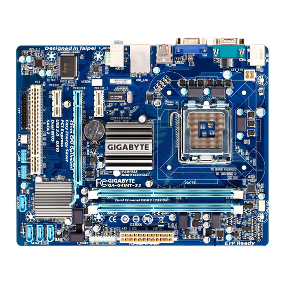
Page 5: Ga-G41Mt-S2 Motherboard Layout
GA-G41MT-S2 Motherboard Layout CPU_FAN KB_MS ATX_12V COMA LGA775 R_USB USB_LAN AUDIO Intel ® F_AUDIO Atheros/Realtek PCIEX1_1 GbE LAN B_BIOS M_BIOS PCIEX16 IT8720/ 8718 PCIEX1_2 SATA2 CODEC Intel ICH7 ® SATA2 0 SYS_FAN F_USB1 F_USB2 Box Contents GA-G41MT-S2 motherboard Motherboard driver disk... -
Page 6: Ga-G41Mt-S2 Motherboard Block Diagram
GA-G41MT-S2 Motherboard Block Diagram PCIe CLK CPU CLK+/- LGA775 (100 MHz) (333/266/200 MHz) Host Interface DDR3 1333(O.C.)/1066/800 MHz Dual Channel Memory PCI Express x16 Intel ® GMCH CLK D-Sub 1 PCI Express x16 (333/266/200 MHz) 2 PCI Express x1 Dual BIOS... -
Page 7: Chapter 1 Hardware Installation
Chapter 1 Hardware Installation Installation Precautions The motherboard contains numerous delicate electronic circuits and components which can become damaged as a result of electrostatic discharge (ESD). Prior to installation, carefully read the user's manual and follow these procedures: Prior to installation, make sure the chassis is suitable for the motherboard. •... -
Page 8: Product Specifications
4 GB. Dual channel memory architecture Š Support for DDR3 1333(O.C.)/1066/800 MHz memory modules Š (Go to GIGABYTE's website for the latest supported memory speeds and memory modules.) Onboard North Bridge: Š... - Page 9 Support for Microsoft Windows 7/Vista/XP Š ® System Form Factor Micro ATX Form Factor; 24.4cm x 19.4cm Š * GIGABYTE reserves the right to make any changes to the product specifications and product-related information without prior notice. - 9 -...
-
Page 10: Installing The Cpu
Read the following guidelines before you begin to install the CPU: Make sure that the motherboard supports the CPU. • (Go to GIGABYTE's website for the latest CPU support list.) Always turn off the computer and unplug the power cord from the power outlet before installing the •... -
Page 11: Installing The Memory
Make sure that the motherboard supports the memory. It is recommended that memory of the same • capacity, brand, speed, and chips be used. (Go to GIGABYTE's website for the latest supported memory speeds and memory modules.) Always turn off the computer and unplug the power cord from the power outlet before installing the •... -
Page 12: Back Panel Connectors
Back Panel Connectors PS/2 Keyboard and PS/2 Mouse Port Use the upper port (green) to connect a PS/2 mouse and the lower port (purple) to connect a PS/2 keyboard. Serial Port Use the serial port to connect devices such as a mouse, modem or other peripherals. D-Sub Port The D-Sub port supports a 15-pin D-Sub connector. -
Page 13: Internal Connectors
Internal Connectors ATX_12V F_AUDIO F_USB1/F_USB2 CPU_FAN SYS_FAN CLR_CMOS SATA2 0/1/2/3 F_PANEL Read the following guidelines before connecting external devices: First make sure your devices are compliant with the connectors you wish to connect. • Before installing the devices, be sure to turn off the devices and your computer. Unplug the power •... - Page 14 1/2) ATX_12V/ATX (2x2 12V Power Connector and 2x12 Main Power Connector) With the use of the power connector, the power supply can supply enough stable power to all the components on the motherboard. Before connecting the power connector, first make sure the power supply is turned off and all devices are properly installed.
-
Page 15: Fan Headers
3/4) CPU_FAN/SYS_FAN (Fan Headers) The motherboard has a 4-pin CPU fan header (CPU_FAN) and a 3-pin (SYS_FAN) system fan header. Most fan headers possess a foolproof insertion design. When connecting a fan cable, be sure to connect it in the correct orientation (the black connector wire is the ground wire). -
Page 16: Front Panel Header
6) F_PANEL (Front Panel Header) Connect the power switch, reset switch, speaker and system status indicator on the chassis front panel to this header according to the pin assignments below. Note the positive and negative pins before connecting the cables. SPEAK- PWR- Power LED... -
Page 17: Front Panel Audio Header
7) F_AUDIO (Front Panel Audio Header) The front panel audio header supports Intel High Definition audio (HD) and AC'97 audio. You may connect your chassis front panel audio module to this header. Make sure the wire assignments of the module connector match the pin assignments of the motherboard header. -
Page 18: Parallel Port Header
9) LPT (Parallel Port Header) The LPT header can provide one parallel port via an optional LPT port cable. For purchasing the optional LPT port cable, please contact the local dealer. Pin No. Definition Pin No. Definition STB- AFD- ERR- INIT- ACK- SLIN-... -
Page 19: Battery
11) BAT (Battery) The battery provides power to keep the values (such as BIOS configurations, date, and time information) in the CMOS when the computer is turned off. Replace the battery when the battery voltage drops to a low level, or the CMOS values may not be accurate or may be lost. You may clear the CMOS values by removing the battery: Turn off your computer and unplug the power cord. -
Page 20: Chapter 2 Bios Setup
To see more advanced BIOS Setup menu options, you can press <Ctrl> + <F1> in the main menu of the BIOS Setup program. To upgrade the BIOS, use either the GIGABYTE Q-Flash or @BIOS utility. Q-Flash allows the user to quickly and easily upgrade or back up BIOS without entering the operating •... -
Page 21: Mb Intelligent Tweaker(M.i.t.)
If you do not find the settings you want in the Main Menu or a submenu, press <Ctrl>+<F1> to • access more advanced options. Load Optimized Defaults item to set your When the system is not stable as usual, select the •... - Page 22 CMOS Setup Utility-Copyright (C) 1984-2011 Award Software MB Intelligent Tweaker(M.I.T.) Item Help x CAS Latency Time Auto Menu Level ` x tRCD Auto x tRP Auto x tRAS Auto >>>>> Advanced Timing Control ` Advanced Timing Control [Press Enter] ******** Mother Board Voltage Control ******** Voltage Types Normal Current...
- Page 23 CPU Host Frequency (Mhz) & Allows you to manually set the CPU host frequency. The adjustable range is from 100 MHz to 1200 MHz. This item is configurable only if the CPU Host Clock Control option is enabled. Important: It is highly recommended that the CPU frequency be set in accordance with the CPU specifications.
- Page 24 CMOS Setup Utility-Copyright (C) 1984-2011 Award Software Advanced Timing Control Item Help x tRRD Auto Menu Level `` x tWTR Auto x tWR Auto x tRFC Auto x tRTP Auto x Command Rate (CMD) Auto >>>>> Channel A ` Channel A Timing Settings [Press Enter] ` Channel A Driving Settings [Press Enter]...
- Page 25 tRD Phase0 Adjustment & Options are: Auto (default), 0-Normal, 1-Advanced. tRD Phase1 Adjustment & Options are: Auto (default), 0-Normal, 1-Advanced. tRD Phase2 Adjustment & Options are: Auto (default), 0-Normal, 1-Advanced. tRD Phase3 Adjustment & Options are: Auto (default), 0-Normal, 1-Advanced. Trd2rd(Different Rank) &...
- Page 26 Driving Strength Profile & Options are: Auto (default). Data Driving Pull-Up Level & Options are: Auto (default), +8~-7. Cmd Driving Pull-Up Level & Options are: Auto (default), +8~-7. Ctrl Driving Pull-Up Level & Options are: Auto (default), +8~-7. Clk Driving Pull-Up Level &...
-
Page 27: Standard Cmos Features
Standard CMOS Features CMOS Setup Utility-Copyright (C) 1984-2011 Award Software Standard CMOS Features Item Help Date (mm:dd:yy) Wed, Nov 30 2011 Menu Level ` Time (hh:mm:ss) 22:31:24 IDE Channel 0 Master [None] IDE Channel 0 Slave [None] IDE Channel 1 Master [None] IDE Channel 1 Slave [None]... -
Page 28: Advanced Bios Features
Advanced BIOS Features CMOS Setup Utility-Copyright (C) 1984-2011 Award Software Advanced BIOS Features Item Help ` Hard Disk Boot Priority [Press Enter] Menu Level ` Quick Boot [Disabled] EFI CD/DVD Boot Option [Auto] First Boot Device [Hard Disk] Second Boot Device [CDROM] Third Boot Device [Legacy LAN]... - Page 29 CPU Multi-Threading & (Note) Allows you to determine whether to enable all CPU cores and multi-threading function when using an Intel CPU that supports multi-core technology. This feature only works for operating systems that support multi-processor mode. Enabled Enables all CPU cores and multi-threading capability. (Default) Disabled Enables only one CPU core.
-
Page 30: Advanced Chipset Features
Advanced Chipset Features CMOS Setup Utility-Copyright (C) 1984-2011 Award Software Advanced Chipset Features Item Help ** VGA Setting ** Menu Level ` Onboard VGA [Enable If No Ext PEG] Init Display First [PCI] PAVP Mode [PAVP Lite Mode] PAVP Lite Mode [32MB] x Paranoid PAVP Mode (32+96)128MB... -
Page 31: Integrated Peripherals
Integrated Peripherals CMOS Setup Utility-Copyright (C) 1984-2011 Award Software Integrated Peripherals Item Help Azalia Codec [Auto] Menu Level ` Onboard H/W LAN [Enabled] ` SMART LAN [Press Enter] Onboard LAN Boot ROM [Disabled] Onboard Serial Port 1 [3F8/IRQ4] Onboard Parallel Port [378/IRQ7] Parallel Port Mode [SPP]... -
Page 32: Power Management Setup
Parallel Port Mode & Selects an operating mode for the onboard parallel (LPT) port. Options are: SPP (Standard Parallel Port) (default), EPP (Enhanced Parallel Port), ECP (Extended Capabilities Port), ECP+EPP. USB 1.0 Controller & Enables or disables the integrated USB 1.0 controller. (Default: Enabled) Disabled will turn off all of the USB functionalities below. - Page 33 Soft-Off by PWR-BTTN & Configures the way to turn off the computer in MS-DOS mode using the power button. Instant-Off Press the power button and then the system will be turned off instantly. (Default) Delay 4 Sec. Press and hold the power button for 4 seconds to turn off the system. If the power button is pressed for less than 4 seconds, the system will enter suspend mode.
-
Page 34: Pnp/Pci Configurations
AC Back Function & Determines the state of the system after the return of power from an AC power loss. Soft-Off The system stays off upon the return of the AC power. (Default) Full-On The system is turned on upon the return of the AC power. Memory The system returns to its last known awake state upon the return of the AC power. -
Page 35: Load Fail-Safe Defaults
Current Voltage(V) Vcore/DDR15V/+3.3V/+12V & Displays the current system voltages. Current CPU Temperature & Displays current CPU temperature. Current CPU/SYSTEM FAN Speed (RPM) & Displays current CPU/system fan speed. CPU Warning Temperature & Sets the warning threshold for CPU temperature. When CPU temperature exceeds the threshold, BIOS will emit warning sound. -
Page 36: Load Optimized Defaults
2-12 Load Optimized Defaults CMOS Setup Utility-Copyright (C) 1984-2011 Award Software MB Intelligent Tweaker(M.I.T.) PC Health Status Standard CMOS Features Load Fail-Safe Defaults Advanced BIOS Features Load Optimized Defaults Advanced Chipset Features Set Supervisor Password Integrated Peripherals Set User Password Load Optimized Defaults (Y/N)? N Power Management Setup Save &... -
Page 37: Save & Exit Setup
2-14 Save & Exit Setup CMOS Setup Utility-Copyright (C) 1984-2011 Award Software MB Intelligent Tweaker(M.I.T.) PC Health Status Standard CMOS Features Load Fail-Safe Defaults Advanced BIOS Features Load Optimized Defaults Save to CMOS and EXIT (Y/N)? Y Advanced Chipset Features Set Supervisor Password Integrated Peripherals Set User Password... -
Page 38: Chapter 3 Drivers Installation
Chapter 3 Drivers Installation Before installing the drivers, first install the operating system. • After installing the operating system, insert the motherboard driver disk into your optical drive. The • driver Autorun screen is automatically displayed which looks like that shown in the screen shot below. -
Page 39: Regulatory Statements
"end of life" product. Restriction of Hazardous Substances (RoHS) Directive Statement GIGABYTE products have not intended to add and safe from hazardous substances (Cd, Pb, Hg, Cr+6, PBDE and PBB). The parts and components have been carefully selected to meet RoHS requirement. Moreover, we at GIGABYTE are continuing our efforts to develop products that do not use internationally banned toxic chemicals. - Page 40 - 40 -...
- Page 41 - 41 -...
- Page 42 - 42 -...
- Page 43 - 43 -...
- Page 44 Tech. and Non-Tech. Support (Sales/Marketing) : http://ggts.gigabyte.com.tw WEB address (English): http://www.gigabyte.com WEB address (Chinese): http://www.gigabyte.tw You may go to the GIGABYTE website, select your language in the language list on the top right corner of the website. GIGABYTE Global Service System •...
Need help?
Do you have a question about the GA-G41MT-S2 and is the answer not in the manual?
Questions and answers