
Subscribe to Our Youtube Channel
Related Manuals for ASROCK H67M-GE/THW


Summary of Contents for ASROCK H67M-GE/THW
-
Page 1: User Manual
H67M-GE/THW User Manual Version 1.0 Published October 2010 Copyright©2010 ASRock INC. All rights reserved. -
Page 2: Copyright Notice
In no event shall ASRock, its directors, of cers, employees, or agents be liable for any indirect, special, incidental, or consequential damages (including damages for... -
Page 3: Table Of Contents
Contents 1 Introduction ............5 1.1 Package Contents ............5 1.2 Speci cations ..............6 1.3 Motherboard Layout ............12 1.4 I/O Panel ..............13 2 Installation ............15 2.1 Screw Holes ..............15 2.2 Pre-installation Precautions ......... 15 2.3 CPU Installation ............. 16 2.4 Installation of Heatsink and CPU fan ...... - Page 4 3 UEFI SETUP UTILITY ..........42 3.1 Introduction ..............42 3.1.1 UEFI Menu Bar ............ 42 3.1.2 Navigation Keys ........... 43 3.2 Main Screen ..............43 3.3 Advanced Screen ............44 3.3.1 CPU Con guration ..........45 3.3.2 Intel IGD SWSCI OpRegion Con guration... 47 3.3.3 Integrated Clock Chip Con guration ....
-
Page 5: Introduction
In case any modi cations of this manual occur, the updated version will be available on ASRock website without further notice. You may nd the latest VGA cards and CPU support lists on ASRock website as well. ASRock website http://www.asrock.com... -
Page 6: Speci Cations
Specifications - Micro ATX Form Factor: 9.6-in x 9.6-in, 24.4 cm x 24.4 cm Platform - Solid Capacitor for CPU power ® - Supports 2nd Generation Intel Core i7 / i5 / i3 in LGA1155 Package - 4 + 1 Power Phase Design ®... - Page 7 - PCIE x1 Gigabit LAN 10/100/1000 Mb/s - Realtek RTL8111E - Supports Wake-On-LAN - Supports LAN Cable Detection - Supports Energy Ef cient Ethernet 802.3az I/O Panel Rear Panel I/O - 1 x PS/2 Keyboard Port - 1 x VGA/D-Sub Port - 1 x VGA/DVI-D Port - 1 x HDMI Port - 1 x Optical SPDIF Out Port...
- Page 8 Certifi cations - ErP/EuP Ready (ErP/EuP ready power supply is required) (see CAUTION 15) * For detailed product information, please visit our website: http://www.asrock.com WARNING Please realize that there is a certain risk involved with overclocking, including adjusting the setting in the BIOS, applying Untied Overclocking Technology, or using the third-party overclocking tools.
- Page 9 ASRock Extreme Tuning Utility (AXTU). ASRock website: http://www.asrock.com ASRock Instant Flash is a BIOS ash utility embedded in Flash ROM. This convenient BIOS update tool allows you to update system BIOS without entering operating systems rst like MS-DOS or Windows ®...
- Page 10 10. To experience intuitive motion controlled games is no longer only avail- able at Wii. ASRock AIWI utility introduces a new way of PC gaming operation. ASRock AIWI is the world's rst utility to turn your iPhone/iPod touch as a game joystick to control your PC games. All you have to do is...
- Page 11 15. EuP, stands for Energy Using Product, was a provision regulated by Eu- ropean Union to de ne the power consumption for the completed system. According to EuP, the total AC power of the completed system shall be under 1.00W in off mode condition. To meet EuP standard, an EuP ready motherboard and an EuP ready power supply are required.
-
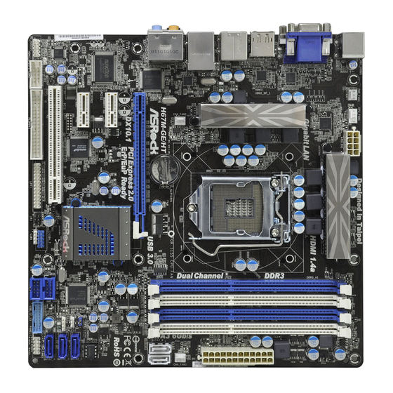
Page 12: Motherboard Layout
ATX12V1 B: USB1 HDMI 1.4a Gigabit LAN USB 2.0 T: USB2 B: USB3 USB 3.0 Top: T: USB4 RJ-45 B: USB5 CMOS H67M-GE/THW Battery USB 3.0 PCIE1 PCI Express 2.0 DX10.1 ErP/EuP Ready RoHS PCIE2 Intel 64Mb BIOS PCIE3 CLRCMOS1... -
Page 13: I/O Panel
1.4 I/O Panel USB 2.0 Ports (USB01) ** 9 Front Speaker (Lime) VGA/D-Sub Port Microphone (Pink) USB 2.0 Ports (USB23) USB 3.0 Ports (USB45) LAN RJ-45 Port eSATA2 Port Central / Bass (Orange) VGA/HDMI Port Rear Speaker (Black) VGA/DVI-D Port Optical SPDIF Out Port PS/2 Keyboard Port (Purple) Line In (Light Blue) - Page 14 To enable Multi-Streaming function, you need to connect a front panel audio cable to the front panel audio header. After restarting your computer, you will nd “Mixer” tool on your system. Please select “Mixer ToolBox” , click “Enable playback multi-streaming”, and click “ok”.
-
Page 15: Installation
Chapter 2: Installation This is a Micro ATX form factor (9.6" x 9.6", 24.4 x 24.4 cm) motherboard. Before you install the motherboard, study the con guration of your chassis to ensure that the motherboard ts into it. Make sure to unplug the power cord before installing or removing the motherboard. -
Page 16: Cpu Installation
2.3 CPU Installation For the installation of Intel 1155-Pin CPU, please follow the steps below. Load Plate Load Lever Socket Body Contact Array 1155-Pin Socket Overview Before you insert the 1155-Pin CPU into the socket, please check if the CPU surface is unclean or if there is any bent pin on the socket. Do not force to insert the CPU into the socket if above situation is found. - Page 17 Step 3. Insert the 1155-Pin CPU: Step 3-1. Hold the CPU by the edge where is marked with black line. Step 3-2. Orient the CPU with IHS (Integrated Heat Sink) up. Locate Pin1 and the two orientation key notches. orientation key notch alignment key Pin1 Pin1...
-
Page 18: Installation Of Cpu Fan And Heatsink
Installation of CPU Fan and Heatsink This motherboard is equipped with 1155-Pin socket that supports Intel 1155-Pin CPU. Please adopt the type of heatsink and cooling fan compliant with Intel 1155- Pin CPU to dissipate heat. Before you installed the heatsink, you need to spray thermal interface material between the CPU and the heatsink to improve heat dis- sipation. -
Page 19: Installation Of Memory Modules (Dimm)
2.5 Installation of Memory Modules (DIMM) This motherboard provides four 240-pin DDR3 (Double Data Rate 3) DIMM slots, and supports Dual Channel Memory Technology. For dual channel con- guration, you always need to install identical (the same brand, speed, size and chip-type) DDR3 DIMM pair in the slots of the same color. -
Page 20: Installing A Dimm
Installing a DIMM Please make sure to disconnect power supply before adding or removing DIMMs or the system components. Step 1. Unlock a DIMM slot by pressing the retaining clips outward. Step 2. Align a DIMM on the slot such that the notch on the DIMM matches the break on the slot. -
Page 21: Expansion Slots (Pci And Pci Express Slots)
2.6 Expansion Slots (PCI and PCI Express Slots) There are 1 PCI slot and 3 PCI Express slots on this motherboard. PCI slots: PCI slots are used to install expansion cards that have the 32-bit PCI interface. PCIE slots: PCIE2 / PCIE3 (PCIE x1 slot; White) is used for PCI Express cards with x1 lane width cards, such as Gigabit LAN card, SATA2 card, etc. -
Page 22: Dual Monitor And Surround Display Features
2.7 Dual Monitor and Surround Display Features Dual Monitor Feature This motherboard supports dual monitor feature. With the internal VGA output sup- port (DVI-D, D-Sub and HDMI), you can easily enjoy the bene ts of dual monitor feature without installing any add-on VGA card to this motherboard. This mother- board also provides independent display controllers for DVI-D, D-Sub and HDMI to support dual VGA output so that DVI-D, D-sub and HDMI can drive same or different display contents. - Page 23 Surround Display Feature This motherboard supports surround display upgrade. With the internal VGA output support (DVI-D, D-Sub and HDMI) and external add-on PCI Express VGA cards, you can easily enjoy the bene ts of surround display feature. Please refer to the following steps to set up a surround display environment: 1.
- Page 24 ® For Windows 7 / 7 64-bit / Vista / Vista 64-bit OS: Right click the desktop, choose “Personalize”, and select the “Display Settings” tab so that you can adjust the parameters of the multi-monitor according to the steps below. A.
-
Page 25: Jumpers Setup
2.8 Jumpers Setup The illustration shows how jumpers are setup. When the jumper cap is placed on pins, the jumper is “Short”. If no jumper cap is placed on pins, the jumper is “Open”. The illustration shows a 3-pin jumper whose pin1 and pin2 are “Short”... -
Page 26: Onboard Headers And Connectors
2.9 Onboard Headers and Connectors Onboard headers and connectors are NOT jumpers. Do NOT place jumper caps over these headers and connectors. Placing jumper caps over the headers and connectors will cause permanent damage of the motherboard! FDD connector (33-pin FLOPPY1) (see p.12 No. - Page 27 (9-pin USB8_9) USB_PWR (see p.12 No. 21) DUMMY USB_PWR (9-pin USB10_11) (see p.12 No. 22) USB_PWR P-11 P+11 DUMMY P+10 P-10 USB_PWR USB 3.0 Header Besides two default USB 3.0 IntA_P2_D+ IntA_P2_D- ports on the I/O panel, there is (19-pin USB_12_13) IntA_P2_SSTX+ IntA_P2_SSTX- one USB 3.0 header on this...
- Page 28 Front Panel Audio Header This is an interface for front PRESENCE# panel audio cable that allows (9-pin HD_AUDIO1) MIC_RET OUT_RET convenient connection and (see p.12 No. 29) control of audio devices. OUT2_L J_SENSE OUT2_R MIC2_R MIC2_L 1. High De nition Audio supports Jack Sensing, but the panel wire on the chassis must support HDA to function correctly.
- Page 29 HDLED (Hard Drive Activity LED): Connect to the hard drive activity LED on the chassis front panel. The LED is on when the hard drive is reading or writing data. The front panel design may differ by chassis. A front panel module mainly consists of power switch, reset switch, power LED, hard drive activity LED, speaker and etc.
- Page 30 ATX Power Connector Please connect an ATX power supply to this connector. (24-pin ATXPWR1) (see p.12 No. 7) Though this motherboard provides 24-pin ATX power connector, it can still work if you adopt a traditional 20-pin ATX power supply. To use the 20-pin ATX power supply, please plug your power supply along with Pin 1 and Pin 13.
- Page 31 The Installation Guide of Front USB 3.0 Panel Step 1 Screw the 2.5” HDD/SSD to the Front Prepare the bundled Front USB 3.0 Panel, four Step 2 USB 3.0 Panel with four HDD screws. HDD screws, and six chassis screws. Step 3 Screw the Front USB 3.0 Panel to the Intall the Front USB 3.0 Panel into the 2.5”...
-
Page 32: Serial Ata (Sata) / Serial Ataii (Sataii) Hard Disks Installation
2.10 Serial ATA (SATA) / Serial ATAII (SATAII) Hard Disks Installation ® This motherboard adopts Intel H67 chipset that supports Serial ATA (SATA) / Serial ATAII (SATAII) hard disks and RAID (RAID 0, RAID 1, RAID 10, RAID 5 and Intel Rapid Storage) functions. -
Page 33: Hot Plug And Hot Swap Functions For Sata / Sataii Hdds
2.12 Hot Plug and Hot Swap Functions for SATA / SATAII HDDs This motherboard supports Hot Plug and Hot Swap functions for SATA / SATAII in ® RAID / AHCI mode. Intel H67 chipset provides hardware support for Advanced Host controller Interface (AHCI), a new programming interface for SATA host controllers developed thru a joint industry effort. -
Page 34: Sata / Sataii / Sata3 Hdd Hot Plug Feature And Operation Guide
SATA / SATAII / SATA3 Hot Plug support information of our motherboard is indicated in the product spec on our website: www.asrock.com 2. Make sure your SATA / SATAII / SATA3 HDD can support Hot Plug function from your dealer or HDD user manual. - Page 35 How to Hot Plug a SATA / SATAII / SATA3 HDD: Points of attention, before you process the Hot Plug: Please do follow below instruction sequence to process the Hot Plug, improper procedure will cause the SATA / SATAII / SATA3 HDD damage and data loss. Step 1 Step 2 Please connect SATA power cable 1x4-pin end...
-
Page 36: Driver Installation Guide
2.15 Driver Installation Guide To install the drivers to your system, please insert the support CD to your optical drive rst. Then, the drivers compatible to your system can be auto-detected and listed on the support CD driver page. Please follow the order from up to bottom side to install those required drivers. -
Page 37: Setting Up A "Raid Ready" System
STEP 3: Use “RAID Installation Guide” to set RAID confi guration. Before you start to con gure the RAID function, you need to check the installation guide in the Support CD for proper con guration. Please refer to the document in the Support CD, “Guide to SATA Hard Disks Installation and RAID Con guration”, which is located in the folder at the following path: .. -
Page 38: Migrating A "Raid Ready" System To Raid 0,
® 5. Finish the Windows installation and install all necessary drivers. 6. Install the Intel(R) Rapid Storage software via the CD-ROM included with your motherboard or after downloading it from the Internet. This will add the Intel(R) Rapid Storage Console which can be used to manage the RAID con guration. 7. -
Page 39: Installing Windows ® 7 / 7 64-Bit / Vista
2.16.4 Installing Windows 7 / 7 64-bit / Vista / Vista 64-bit With ® RAID Functions ® If you want to install Windows 7 / 7 64-bit / Vista / Vista 64-bit on your SATA / SATAII / SATA3 HDDs with RAID functions, please follow below steps. STEP 1: Set up BIOS. -
Page 40: Xp / Xp 64-Bit Without Raid Functions
2.17 Installing Windows 7 / 7 64-bit / Vista / Vista 64-bit / XP ® / XP 64-bit Without RAID Functions ® If you want to install Windows 7 / 7 64-bit / Vista / Vista 64-bit / XP / XP 64- bit OS on your SATA / SATAII / SATA3 HDDs without RAID functions, please follow below procedures according to the OS you install. -
Page 41: Installing Windows ® 7 / 7 64-Bit / Vista
2.17.2 Installing Windows 7 / 7 64-bit / Vista / Vista 64-bit ® Without RAID Functions ® If you want to install Windows 7 / 7 64-bit / Vista / Vista 64-bit OS on your SATA / SATAII / SATA3 HDDs without RAID functions, please follow below steps. Using SATA / SATAII / SATA3 HDDs with NCQ function STEP 1: Set Up BIOS. -
Page 42: Uefi Setup Utility
Chapter 3: UEFI SETUP UTILITY Introduction This section explains how to use the UEFI SETUP UTILITY to con gure your system. The UEFI chip on the motherboard stores the UEFI SETUP UTILITY. You may run the UEFI SETUP UTILITY when you start up the computer. Please press <F2>... -
Page 43: Navigation Keys
3.1.2 Navigation Keys Please check the following table for the function description of each navigation key. Navigation Key(s) Function Description Moves cursor left or right to select Screens Moves cursor up or down to select items To change option for the selected items + / - To bring up the selected screen <Enter>... -
Page 44: Advanced Screen
Setting wrong values in this section may cause the system to malfunction. ASRock Instant Flash ASRock Instant Flash is a UEFI flash utility embedded in Flash ROM. This convenient UEFI update tool allows you to update system UEFI ® without entering operating systems rst like MS-DOS or Windows . -
Page 45: Cpu Configuration
3.3.1 CPU Configuration CPU Ratio Setting Use this item to change the ratio value of this motherboard. Intel SpeedStep Technology Intel SpeedStep technology is Intel’s new power saving technology. Pro- cessor can switch between multiple frequency and voltage points to en- able power savings. - Page 46 ® system that includes optimization for this technology, such as Microsoft ® ® ® Windows XP / Vista / 7. Set to [Enabled] if using Microsoft Windows XP, Vista , 7, or Linux kernel version 2.4.18 or higher. This option will be hidden if the installed CPU does not support Hyper-Threading technology.
-
Page 47: Intel Igd Swsci Opregion Con Guration
3.3.2 Intel IGD SWSCI OpRegion Configuration DVMT Mode Select Use this option to adjust DVMT mode. The default value is [DVMT Mode]. DVMT (Dynamic Video Memory Technology) is an architecture that offers breakthrough performance for the motherboard through ef cient memory utilization. -
Page 48: Integrated Clock Chip Con Guration
3.3.3 Integrated Clock Chip Configuration DIV-1S Integrated Clock Control options. DIV-2S Integrated Clock Control options. DIV3 Integrated Clock Control options. DIV4 Integrated Clock Control options. DIV-1NS Integrated Clock Control options. DIV-2NS Integrated Clock Control options. -
Page 49: Dram Configuration
3.3.4 DRAM Configuration DRAM Frequency If [Auto] is selected, the motherboard will detect the memory module(s) inserted and assigns appropriate frequency automatically. CAS# Latency (tCL) Use this item to change CAS# Latency (tCL) Auto/Manual setting. The default is [Auto]. RAS# to CAS# Delay (tRCD) Use this item to change RAS# to CAS# Delay (tRCD) Auto/Manual setting. - Page 50 Write to Read Delay (tWTR) Use this item to change Write to Read Delay (tWTR) Auto/Manual setting. The default is [Auto]. Read to Precharge (tRTP) Use this item to change Read to Precharge (tRTP) Auto/Manual setting. The default is [Auto]. Four Activate Window (tFAW) Use this item to change Four Activate Window (tFAW) Auto/Manual set- ting.
-
Page 51: North Bridge Configuration
3.3.5 North Bridge Configuration Low MMIO Align Low MMIO resources align at 64MB/1024MB. The default value is [64MB]. VT-d ® ® Use this to enable or disable Intel VT-d technology (Intel Virtualization Technology for Directed I/O). The default value of this feature is [Disabled]. Primary Graphics Adapter This allows you to select the boot graphic adapter priority. -
Page 52: South Bridge Configuration
3.3.6 South Bridge Configuration Restore on AC/Power Loss This allows you to set the power state after an unexpected AC/power loss. If [Power Off] is selected, the AC/power remains off when the power recovers. If [Power On] is selected, the AC/power resumes and the system starts to boot up when the power recovers. -
Page 53: Storage Configuration
3.3.7 Storage Configuration SATA Mode Use this to select SATA mode. Con guration options: [IDE Mode], [AHCI Mode] and [RAID Mode]. The default value is [IDE Mode]. AHCI (Advanced Host Controller Interface) supports NCQ and other new features that will improve SATA disk perfor- mance but IDE mode does not have these advantages. -
Page 54: Super Io Configuration
3.3.8 Super IO Configuration OnBoard Floppy Controller Use this item to enable or disable oppy drive controller. Serial Port Use this item to enable or disable the onboard serial port. Serial Port Address Use this item to set the address for the onboard serial port. Con guration options: [Auto], [3F8 / IRQ4], [2F8 / IRQ3], [3E8 / IRQ4], [2E8 / IRQ3]. -
Page 55: Voltage Configuration
3.3.9 Voltage Configuration CPU Core Voltage Offset Use this to select CPU Core Voltage Offset. Con guration options: [Auto], [-0.300V] to [+0.500V]. The default value is [Auto]. IGPU Voltage Use this to select IGPU Voltage. Con guration options: [Auto], [Offset Mode] and [Fix Mode]. The default value is [Auto]. DRAM Voltage Use this to select DRAM Voltage. -
Page 56: Acpi Configuration
3.3.10 ACPI Configuration Suspend to RAM Use this item to select whether to auto-detect or disable the Suspend-to- RAM feature. Select [Auto] will enable this feature if the OS supports it. PS/2 Keyboard Power On Use this item to enable or disable PS/2 keyboard to turn on the system from the power-soft-off mode. -
Page 57: Usb Configuration
3.3.11 USB Configuration USB 2.0 Controller Use this item to enable or disable the use of USB 2.0 controller. USB 3.0 Controller Use this item to enable or disable the use of USB 3.0 controller. Legacy USB Support Use this option to select legacy support for USB devices. There are four con guration options: [Enabled], [Auto], [Disabled] and [UEFI Setup Only]. -
Page 58: Hardware Health Event Monitoring Screen
3.4 Hardware Health Event Monitoring Screen In this section, it allows you to monitor the status of the hardware on your system, including the parameters of the CPU temperature, motherboard temperature, CPU fan speed, chassis fan speed, and the critical voltage. CPU Fan Setting This allows you to set the CPU fan speed. -
Page 59: Boot Screen
3.5 Boot Screen In this section, it will display the available devices on your system for you to con g- ure the boot settings and the boot priority. Setup Prompt Timeout This shows the number of seconds to wait for setup activation key. 65535(0XFFFF) means inde nite waiting. -
Page 60: Security Screen
3.6 Security Screen In this section, you may set or change the supervisor/user password for the system. For the user password, you may also clear it. -
Page 61: Exit Screen
3.7 Exit Screen Save Changes and Exit When you select this option, it will pop-out the following message, “Save con guration changes and exit setup?” Select [OK] to save the changes and exit the UEFI SETUP UTILITY. Discard Changes and Exit When you select this option, it will pop-out the following message, “Discard changes and exit setup?”... -
Page 62: Software Support
Click on a speci c item then follow the installation wizard to install it. 4.2.4 Contact Information If you need to contact ASRock or want to know more about ASRock, welcome to visit ASRock’s website at http://www.asrock.com; or you may contact your dealer for further information. -
Page 63: Installing Os On A Hdd Larger Than 2Tb
Installing OS on a HDD Larger Than 2TB ® This motherboard is adopting UEFI BIOS that allows Windows OS to be installed on a large size HDD (>2TB). Please follow below procedure to install the operating system. ® 1. Please make sure to use Windows Vista 64-bit (with SP1 or above) or ®...
Need help?
Do you have a question about the H67M-GE/THW and is the answer not in the manual?
Questions and answers