Table of Contents
Advertisement
Advertisement
Table of Contents

Related Manuals for ASROCK H670 Steel Legend


Summary of Contents for ASROCK H670 Steel Legend
- Page 2 (including damages for loss of profits, loss of business, loss of data, interruption of business and the like), even if ASRock has been advised of the possibility of such damages arising from any defect or error in the documentation or product.
- Page 3 If you require assistance please call ASRock Tel : +886-2-28965588 ext.123 (Standard International call charges apply) The terms HDMI®...
- Page 4 ES OF ANY KIND WHETHER UNDER THIS AGREEMENT OR OTHERWISE, EVEN IF INTEL HAS BEEN ADVISED OF THE POSSIBILITY OF SUCH DAMAGES. LICENSE TO USE COMMENTS AND SUGGESTIONS. This Agreement does NOT obligate Licensee to provide Intel with comments or suggestions regarding the Software. However, if Licensee provides Intel with comments or suggestions for the modification, correction, improvement or enhancement of (a) the Software or (b) Intel products or processes that work with the Software, Licensee grants to Intel a non-exclusive, worldwide,...
-
Page 5: Table Of Contents
Contents Chapter 1 Introduction Package Contents Specifications Motherboard Layout I/O Panel Chapter 2 Installation Installing the CPU Installing the CPU Fan and Heatsink Installing Memory Modules (DIMM) Expansion Slots (PCIe Slots) Jumpers Setup Onboard Headers and Connectors Smart Button Post Status Checker CrossFire Operation Guide 2.9.1 Installing Two CrossFire... - Page 6 Chapter 3 Software and Utilities Operation Installing Drivers ASRock Motherboard Utility (A-Tuning) 3.2.1 Installing ASRock Motherboard Utility (A-Tuning) 3.2.2 Using ASRock Motherboard Utility (A-Tuning) ASRock Live Update & APP Shop 3.3.1 UI Overview 3.3.2 Apps 3.3.3 BIOS & Drivers 3.3.4 Setting...
- Page 7 4.6.4 Intel(R) Thunderbolt 4.6.5 Super IO Configuration 4.6.6 ACPI Configuration 4.6.7 USB Configuration 4.6.8 Trusted Computing Tools Hardware Health Event Monitoring Screen Security Screen 4.10 Boot Screen 4.11 Exit Screen...
-
Page 8: Chapter 1 Introduction
ASRock’s website without further notice. If you require technical support related to this motherboard, please visit our website for specific information about the model you are using. You may find the latest VGA cards and CPU support list on ASRock’s website as well. ASRock website http://www.asrock.com. -
Page 9: Specifications
• 4 x DDR4 DIMM Slots • Supports DDR4 non-ECC, un-buffered memory up to 5000+(OC)* * Supports DDR4 3200 natively. * Please refer to Memory Support List on ASRock's website for more information. (http://www.asrock.com/) • Supports ECC UDIMM memory modules (operate in non- ECC mode) • Max. - Page 10 H670 Steel Legend • Dual graphics output: support HDMI and DisplayPort 1.4 ports by independent display controllers • Supports HDMI 2.1 TMDS Compatible with max. resolution up to 4K x 2K (4096x2160) @ 60Hz • Supports DisplayPort 1.4 with DSC (compressed) max.
- Page 11 Technology (M2_2 and M2_3 only) * Supports Intel® Volume Management Device (VMD) * Supports NVMe SSD as boot disks * Supports ASRock U.2 Kit RAID • Supports RAID 0, RAID 1, RAID 5 and RAID 10 for SATA storage devices • Supports RAID 0, RAID 1 and RAID 5 for M.2 NVMe...
- Page 12 • 1 x 4 pin 12V Power Connector (Hi-Density Power Connector) • 1 x Front Panel Audio Connector • 1 x Thunderbolt AIC Connector (5-pin) (Supports ASRock Thunderbolt 4 AIC Card) • 1 x USB 2.0 Header (Supports 2 USB 2.0 ports) (Supports ESD Protection) • 2 x USB 3.2 Gen1 Headers (Support 4 USB 3.2 Gen1 ports)
- Page 13 * For detailed product information, please visit our website: http://www.asrock.com Please realize that there is a certain risk involved with overclocking, including adjusting the setting in the BIOS, applying Untied Overclocking Technology, or using third-party overclocking tools. Overclocking may affect your system’s stability, or even cause damage to the components and devices of your system.
-
Page 14: Motherboard Layout
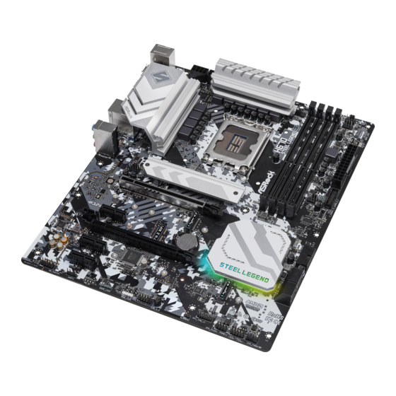
H670 Steel Legend 1.3 Motherboard Layout CPU_FAN2/WP CHA_FAN3/WP ATX12V1 ATX12V2 CPU_FAN1 BOOT DRAM BIOS _FB1 USB 3.2 Gen2 T:USB32_TA_1 B: USB32_TC_1 USB 2.0 Top: T: USB_2 RJ-45 B: USB_3 CHA_FAN1 CHA_FAN2/WP PCIE1 CT11 Intel H670 PCIE2 CMOS Battery T B1... - Page 15 No. Description 8 pin 12V Power Connector (ATX12V1) 4 pin 12V Power Connector (ATX12V2) CPU Fan Connector (CPU_FAN1) 2 x 288-pin DDR4 DIMM Slots (DDR4_A1, DDR4_B1) 2 x 288-pin DDR4 DIMM Slots (DDR4_A2, DDR4_B2) CPU/Water Pump Fan Connector (CPU_FAN2/WP) Addressable LED Header (ADDR_LED3) Addressable LED Header (ADDR_LED2) Post Status Checker (PSC) Chassis/Water Pump Fan Connector (CHA_FAN3/WP)
-
Page 16: I/O Panel
H670 Steel Legend 1.4 I/O Panel No. Description No. Description PS/2 Mouse/Keyboard Port USB 2.0 Ports (USB_2_3) USB 3.2 Gen2 Type-C Port DisplayPort 1.4 (USB32_TC_1) USB 3.2 Gen2 Type-A Port BIOS Flashback Button (USB32_TA_1) 2.5G LAN RJ-45 Port (Dragon USB 2.0 Ports (USB_0_1) - Page 17 ** Function of the Audio Ports in 7.1-channel Configuration: Port Function Light Blue (Rear panel) Rear Speaker Out Lime (Rear panel) Front Speaker Out Pink (Rear panel) Central /Subwoofer Speaker Out Lime (Front panel) Side Speaker Out...
-
Page 18: Chapter 2 Installation
H670 Steel Legend Chapter 2 Installation This is an ATX form factor motherboard. Before you install the motherboard, study the configuration of your chassis to ensure that the motherboard fits into it. Pre-installation Precautions Take note of the following precautions before you install motherboard components or change any motherboard settings. -
Page 19: Installing The Cpu
2.1 Installing the CPU 1. Before you insert the 1700-Pin CPU into the socket, please check if the PnP cap is on the socket, if the CPU surface is unclean, or if there are any bent pins in the socket. Do not force to insert the CPU into the socket if above situation is found. - Page 20 H670 Steel Legend...
- Page 21 Please save and replace the cover if the processor is removed. The cover must be placed if you wish to return the motherboard for after service.
-
Page 22: Installing The Cpu Fan And Heatsink
H670 Steel Legend 2.2 Installing the CPU Fan and Heatsink... -
Page 23: Installing Memory Modules (Dimm)
2.3 Installing Memory Modules (DIMM) This motherboard provides four 288-pin DDR4 (Double Data Rate 4) DIMM slots, and supports Dual Channel Memory Technology. 1. For dual channel configuration, you always need to install identical (the same brand, speed, size and chip-type) DDR4 DIMM pairs. 2. - Page 24 H670 Steel Legend...
-
Page 25: Expansion Slots (Pcie Slots)
2.4 Expansion Slots (PCIe Slots) There are 5 PCIe slots on the motherboard. Before installing an expansion card, please make sure that the power supply is switched off or the power cord is unplugged. Please read the documentation of the expansion card and make necessary hardware settings for the card before you start the installation. -
Page 26: Jumpers Setup
H670 Steel Legend 2.5 Jumpers Setup The illustration shows how jumpers are setup. When the jumper cap is placed on the pins, the jumper is “Short”. If no jumper cap is placed on the pins, the jumper is “Open”. Clear CMOS Jumper... -
Page 27: Onboard Headers And Connectors
2.6 Onboard Headers and Connectors Onboard headers and connectors are NOT jumpers. Do NOT place jumper caps over these headers and connectors. Placing jumper caps over the headers and connectors will cause permanent damage to the motherboard. System Panel Header Connect the power button, PLED+ PLED-... - Page 28 H670 Steel Legend Serial ATA3 Connectors These four SATA3 Right-Angle: connectors support SATA (SATA3_0: data cables for internal see p.7, No. 17)(Upper) storage devices with up to 6.0 (SATA3_1: Gb/s data transfer rate. see p.7, No. 17)(Lower) (SATA3_2: see p.7, No. 16)(Upper) (SATA3_3: see p.7, No.
- Page 29 Front Panel Audio Header This header is for connecting PRESENCE# (9-pin HD_AUDIO1) MIC_RET audio devices to the front OUT_RET (see p.7, No. 26) audio panel. OUT2_L J_SENSE OUT2_R MIC2_R MIC2_L 1. High Definition Audio supports Jack Sensing, but the panel wire on the chassis must support HDA to function correctly.
- Page 30 H670 Steel Legend CPU/Water Pump Fan This motherboard provides Connector a 4-Pin water cooling CPU (4-pin CPU_FAN2/WP) fan connector. If you plan to FAN_VOLTAGE CPU_F AN_SPEED (see p.7, No. 6) connect a 3-Pin CPU water FAN_SPEED_CONTROL cooler fan, please connect it to Pin 1-3.
- Page 31 SPI TPM Header This connector supports SPI SPI_DQ3 SPI_PWR (13-pin SPI_TPM_J1) Trusted Platform Module (TPM) Dummy (see p.7, No. 21) system, which can securely store SPI_MOSI RST# keys, digital certificates, passwords, TPM_PIRQ and data. A TPM system also helps enhance network security, protects SPI_TPM_CS# digital identities, and ensures RSMRST#...
-
Page 32: Smart Button
(BIOS_FB1) to flash the BIOS. (see p.9, No. 10) ASRock BIOS Flashback feature allows you to update BIOS without powering on the system, even without CPU. Before using the BIOS Flashback function, please suspend BitLocker and any encryption or security relying on the TPM. Make sure that you have already stored and backup-ed the recovery key. -
Page 33: Post Status Checker
2.8 Post Status Checker Post Status Checker (PSC) diagnoses the computer when users power on the machine. It emits a red light to indicate whether the CPU, memory, VGA or stor- age is dysfunctional. The lights go off if the four mentioned above are functioning normally. -
Page 34: Crossfire Tm Operation Guide
H670 Steel Legend 2.9 CrossFire Operation Guide This motherboard supports CrossFire that allows you to install up to two identical PCI Express x16 graphics cards. 1. You should only use identical CrossFire -ready graphics cards that are AMD certified. 2. Make sure that your graphics card driver supports AMD CrossFire technology. - Page 35 Step 3 Connect a VGA/DVI/DP/HDMI cable from the monitor to the corresponding port on the graphics card installed to the PCIE1 slot.
-
Page 36: Driver Installation And Setup
H670 Steel Legend 2.9.2 Driver Installation and Setup Step 1 Power on your computer and boot into OS. Step 2 Remove the AMD drivers if you have any VGA drivers installed in your system. The Catalyst Uninstaller is an optional download. We recommend using this utility to uninstall any previously installed Catalyst drivers prior to installation. -
Page 37: Wifi/Bt Pcie Wifi Module And Intel® Cnvi (Integrated Wifi/Bt) Installation Guide
2.10 M.2 WiFi/BT PCIe WiFi Module and Intel® CNVi (Integrated WiFi/BT) Installation Guide The M.2, also known as the Next Generation Form Factor (NGFF), is a small size and versatile card edge connector that aims to replace mPCIe and mSATA. The M.2 Socket (Key E) supports type 2230 WiFi/BT PCIe WiFi module and Intel®... - Page 38 H670 Steel Legend Step 3 Gently insert the WiFi/BT PCIe WiFi module or Intel® CNVi (Integrated WiFi/BT) into the M.2 slot. Please be aware that the module only fits in one orientation. Step 4 Tighten the screw with a screwdriver to secure the module into place.
-
Page 39: M.2_Ssd (Ngff) Module Installation Guide (M2_1)
2.11 M.2_SSD (NGFF) Module Installation Guide (M2_1) The M.2, also known as the Next Generation Form Factor (NGFF), is a small size and versatile card edge connector that aims to replace mPCIe and mSATA. The Hyper M.2 Socket (M2_1, Key M) supports type 2260/2280 PCIe Gen4x4 (64 Gb/s) mode. Installing the M.2_SSD (NGFF) Module Step 1 Prepare a M.2_SSD (NGFF) module... - Page 40 H670 Steel Legend Step 3 Depending on the PCB type and length of your M.2_SSD (NGFF) module, find the corresponding nut location to be used. Step 4 Prepare the M.2 standoff that comes with the package. Then hand tighten the standoff into the desired nut location on the motherboard.
- Page 41 Step 6 Tighten the screw with a screwdriver to secure the M.2 heatsink into place. Please do not overtighten the screw as this might damage the module and M.2 heatsink.
- Page 42 H670 Steel Legend M.2_SSD (NGFF) Module Support List (M2_1) Vendor Interface ADATA PCIe3 x4 ASX7000NP-128GT-C ADATA PCIe3 x4 ASX8000NP-256GM-C ADATA PCIe3 x4 ASX7000NP-256GT-C ADATA PCIe3 x4 ASX8000NP-512GM-C ADATA PCIe3 x4 ASX7000NP-512GT-C Apacer PCIe3 x4 AP240GZ280 Corsair PCIe3 x4 CSSD-F240GBMP500 Intel...
-
Page 43: M.2_Ssd (Ngff) Module Installation Guide (M2_2)
2.12 M.2_SSD (NGFF) Module Installation Guide (M2_2) The M.2, also known as the Next Generation Form Factor (NGFF), is a small size and versatile card edge connector that aims to replace mPCIe and mSATA. The Hyper M.2 Socket (M2_2, Key M) supports type 2242/2260/2280 PCIe Gen4x4 (64 Gb/s) mode. Installing the M.2_SSD (NGFF) Module Step 1 Prepare a M.2_SSD (NGFF) module... - Page 44 H670 Steel Legend Step 3 Move the standoff based on the module type and length. The standoff is placed at the nut location C by default. Skip Step 3 and 4 and go straight to Step 5 if you are going to use the default nut.
- Page 45 XP941-512G (MZHPU512HCGL) SanDisk PCIe SD6PP4M-128G SanDisk PCIe SD6PP4M-256G TEAM PCIe3 x4 TM8FP2240G0C101 TEAM PCIe3 x4 TM8FP2480GC110 PCIe3 x4 WDS256G1X0C-00ENX0 (NVME) PCIe3 x4 WDS512G1X0C-00ENX0 (NVME) For the latest updates of M.2_SSD (NFGG) module support list, please visit our website for details: http://www.asrock.com...
- Page 46 H670 Steel Legend 2.13 M.2_SSD (NGFF) Module Installation Guide (M2_3) The M.2, also known as the Next Generation Form Factor (NGFF), is a small size and versatile card edge connector that aims to replace mPCIe and mSATA. The Hyper M.2 Socket (M2_3, Key M), supports type 2260/2280/22110 SATA3 6.0 Gb/s &...
- Page 47 Step 3 Move the standoff based on the module type and length. The standoff is placed at the nut location C by default. Skip Step 3 and 4 and go straight to Step 5 if you are going to use the default nut. Otherwise, release the standoff by hand.
- Page 48 H670 Steel Legend M.2_SSD (NGFF) Module Support List (M2_3) Vendor Interface ADATA SATA3 AXNS330E-32GM-B ADATA SATA3 AXNS381E-128GM-B ADATA SATA3 AXNS381E-256GM-B ADATA SATA3 ASU800NS38-256GT-C ADATA SATA3 ASU800NS38-512GT-C ADATA PCIe3 x4 ASX7000NP-128GT-C ADATA PCIe3 x4 ASX8000NP-256GM-C ADATA PCIe3 x4 ASX7000NP-256GT-C ADATA PCIe3 x4...
- Page 49 SATA3 VLM100-120G-2280B-RD V-Color SATA3 VLM100-240G-2280RGB V-Color SATA3 VSM100-240G-2280 V-Color SATA3 VLM100-240G-2280B-RD SATA3 WDS100T1B0B-00AS40 SATA3 WDS240G1G0B-00RC30 PCIe3 x4 WDS256G1X0C-00ENX0 (NVME) PCIe3 x4 WDS512G1X0C-00ENX0 (NVME) For the latest updates of M.2_SSD (NFGG) module support list, please visit our website for details: http://www.asrock.com...
-
Page 50: Chapter 3 Software And Utilities Operation
H670 Steel Legend Chapter 3 Software and Utilities Operation 3.1 Installing Drivers The Support CD that comes with the motherboard contains necessary drivers and useful utilities that enhance the motherboard’s features. Running The Support CD To begin using the support CD, insert the CD into your CD-ROM drive. The CD automatically displays the Main Menu if “AUTORUN”... -
Page 51: Asrock Motherboard Utility (A-Tuning)
3.2.1 Installing ASRock Motherboard Utility (A-Tuning) ASRock Motherboard Utility (A-Tuning) can be downloaded from ASRock Live Update & APP Shop. After the installation, you will find the icon “ASRock Mother- board Utility (A-Tuning)“ on your desktop. Double-click the “ASRock Motherboard Utility (A-Tuning)“... - Page 52 H670 Steel Legend OC Tweaker Configurations for overclocking the system. System Info View information about the system. *The System Browser tab may not appear for certain models.
- Page 53 Settings Configure ASRock ASRock Motherboard Utility (A-Tuning). Click to select "Auto run at Windows Startup" if you want ASRock Motherboard Utility (A-Tuning) to be launched when you start up the Windows operating system.
-
Page 54: Asrock Live Update & App Shop
Double-click on your desktop to access ASRock Live Update & APP Shop utility. *You need to be connected to the Internet to download apps from the ASRock Live Update & APP Shop. 3.3.1 UI Overview Category Panel Hot News... -
Page 55: Apps
3.3.2 Apps When the "Apps" tab is selected, you will see all the available apps on screen for you to download. Installing an App Step 1 Find the app you want to install. The most recommended app appears on the left side of the screen. The other various apps are shown on the right. - Page 56 H670 Steel Legend Step 3 If you want to install the app, click on the red icon to start downloading. Step 4 When installation completes, you can find the green "Installed" icon appears on the upper right corner. To uninstall it, simply click on the trash can icon...
- Page 57 Upgrading an App You can only upgrade the apps you have already installed. When there is an available new version for your app, you will find the mark of "New Version" appears below the installed app icon. Step 1 Click on the app icon to see more details. Step 2 Click on the yellow icon to start upgrading.
-
Page 58: Bios & Drivers
H670 Steel Legend 3.3.3 BIOS & Drivers Installing BIOS or Drivers When the "BIOS & Drivers" tab is selected, you will see a list of recommended or critical updates for the BIOS or drivers. Please update them all soon. Step 1 Please check the item information before update. -
Page 59: Setting
3.3.4 Setting In the "Setting" page, you can change the language, select the server location, and determine if you want to automatically run the ASRock Live Update & APP Shop on Windows startup. -
Page 60: Nahimic Audio
H670 Steel Legend 3.4 Nahimic Audio Nahimic audio software provides an incredible high definition sound technology which boosts the audio and voice performance of your system. Nahimic Audio interface is composed of four tabs : Audio, Microphone, Sound Tracker and Settings. -
Page 61: Asrock Polychrome Sync
3.5 ASRock Polychrome SYNC ASRock Polychrome SYNC is a lighting control utility specifically designed for unique indi- viduals with sophisticated tastes to build their own stylish colorful lighting system. Simply by connecting the LED strip, you can customize various lighting schemes and patterns, including Static, Breathing, Strobe, Cycling, Music, Wave and more. - Page 62 H670 Steel Legend Connecting the Addressable RGB LED Strip Connect your Addressable RGB LED strips to the Addressable LED Headers (ADDR_LED1 / ADDR_LED2 / ADDR_LED3) on the motherboard. ADDR_LED2 DO_ADDR VOUT ADDR_LED3 DO_ADDR VOUT ADDR_LED1 DO_ADDR VOUT 1. Never install the RGB LED cable in the wrong orientation; otherwise, the cable may be damaged.
- Page 63 ASRock Polychrome SYNC Utility Now you can adjust the RGB LED color through the ASRock Polychrome SYNC Utility. Download this utility from the ASRock Live Update & APP Shop and start coloring your PC style your way! Drag the tab to customize your preference.
-
Page 64: Chapter 4 Uefi Setup Utility
H670 Steel Legend Chapter 4 UEFI SETUP UTILITY 4.1 Introduction This section explains how to use the UEFI SETUP UTILITY to configure your system. You may run the UEFI SETUP UTILITY by pressing <F2> or <Del> right after you power on the computer, otherwise, the Power-On-Self-Test (POST) will continue with its test routines. -
Page 65: Ez Mode
4.2 EZ Mode The EZ Mode screen appears when you enter the BIOS setup program by default. EZ mode is a dashboard which contains multiple readings of the system’s current status. You can check the most crucial information of your system, such as CPU speed, DRAM frequency, SATA information, fan speed, etc. -
Page 66: Advanced Mode
H670 Steel Legend 4.3 Advanced Mode The Advanced Mode provides more options to configure the BIOS settings. Refer to the following sections for the detailed configurations. To access the EZ Mode, press <F6> or click the "EZ Mode" button at the upper right corner of the screen. -
Page 67: Navigation Keys
4.3.2 Navigation Keys Use < > key or < > key to choose among the selections on the menu bar, and use < > key or < > key to move the cursor up or down to select items, then press <Enter>... -
Page 68: Main Screen
H670 Steel Legend 4.4 Main Screen When you enter the UEFI SETUP UTILITY, the Main screen will appear and display the system overview. The availability and location of BIOS settings can be different for different models and BIOS versions. My Favorite... -
Page 69: Oc Tweaker Screen
4.5 OC Tweaker Screen In the OC Tweaker screen, you can set up overclocking features. Because the UEFI software is constantly being updated, the following UEFI setup screens and descriptions are for reference purpose only, and they may not exactly match what you see on your screen. - Page 70 H670 Steel Legend AVX2 Ratio Offset AVX2 Ratio Offset specifies a negative offset from the CPU Ratio for AVX workloads. AVX is a more stressful workload that lower the AVX ratio to ensure maximum possible ratio for SSE workloads. Core Ratio Extension Mode Enable or disable core ratio above 85 Extension mode.
- Page 71 Intel SpeedStep Technology Intel SpeedStep technology allows processors to switch between multiple frequen- cies and voltage points for better power saving and heat dissipation. Intel Turbo Boost Technology Intel Turbo Boost Technology enables the processor to run above its base operating frequency when the operating system requests the highest performance state.
- Page 72 H670 Steel Legend GT Unlimited Current Limit To unlock voltage regulator current limit completely, you can set this option to Enabled. GT Current Limit Configure the current limit of the GT slice. A lower limit can protect the CPU and save power, while a higher limit may improve performance.
- Page 73 Row Precharge: The number of clock cycles required between the issuing of the precharge command and opening the next row. RAS# Active Time (tRAS) The number of clock cycles required between a bank active command and issuing the precharge command. Command Rate (CR) The delay between when a memory chip is selected and when the first active command can be issued.
- Page 74 H670 Steel Legend tREFI Configure refresh cycles at an average periodic interval. tCKE Configure the period of time the DDR4 initiates a minimum of one refresh command internally once it enters Self-Refresh mode. Turn Around Timing Turn Around Timing Optimization Auto is enabled in general case.
- Page 75 tWRRD_dg Configure between module write to read delay. tWRRD_dr Configure between module write to read delay. tWRRD_dd Configure between module write to read delay. tWRWR_sg Configure between module write to write delay. tWRWR_dg Configure between module write to write delay. tWRWR_dr Configure between module write to write delay.
- Page 76 H670 Steel Legend tRDWR_dr Configure between module read to write delay. tRDWR_dd Configure between module read to write delay. tWRRD_sg Configure between module write to read delay. tWRRD_dg Configure between module write to read delay. tWRRD_dr Configure between module write to read delay.
- Page 77 Initial RTL (A2) Configure round trip latency initial value. Initial RTL (B1) Configure round trip latency initial value. Initial RTL (B2) Configure round trip latency initial value. ODT Setting Dimm ODT Training ODT values will be optimized by Dimm On-Die Termination Training. ODT WR (A1) Configure the memory on die termination resistors' WR for channel A1.
- Page 78 Advanced Setting ASRock Timing Optimization Configure the fast path through the MRC. ASRock DRAM Frequency Optimization Enable/Disable ASRock DRAM Frequency Optimization. When enabled, the DRAM Frequency will run ASRock optimized procedure. MRC Training Respond Time Try Slowest MRC Training. Realtime Memory Timing Configure the realtime memory timings.
- Page 79 [STABLE]: Smaller range voltage for stable system. CPU Core/Cache Voltage Input voltage for the processor by the external voltage regulator. Core/Cache V/F Curve Configure CPU Core/Cache Voltage/Frequency Curve. CPU Core/Cache Load-Line Calibration CPU Core/Cache Load-Line Calibration helps prevent CPU Core/Cache voltage droop when the system is under heavy loading.
- Page 80 H670 Steel Legend +1.05 PCH Voltage Configure the voltage for the +1.05 PCH. AVX Configuration AVX2 Voltage Guardband Scale Factor AVX2 Voltage Guardband Scale Factor controls the voltage guardband applied to AVX2 workloads. A value > 1.00 will increase the voltage guardband, and < 1.00 will decrease the voltage guardband.
- Page 81 E-Core L2 Extra Turbo Voltage Specifies the extra turbo voltage applied while Atom L2 is operating in turbo mode. Uses Mailbox MSR 0x150, cmd 0x10, 0x11. Range 0-2000 mV. E-Core L2 Voltage Offset Specifies the Offset Voltage applied to the Atom L2 domain. This voltage is specified in millivolts.
- Page 82 H670 Steel Legend GT Extra Turbo Voltage Specifies the extra turbo voltage applied while GT is operating in turbo mode. Uses Mailbox MSR 0x150, cmd 0x10, 0x11. Range 0-2000 mV. GT Voltage Offset Specifies the Offset Voltage applied to the GT domain. This voltage is specified in millivolts.
-
Page 83: Advanced Screen
4.6 Advanced Screen In this section, you may set the configurations for the following items: CPU Configuration, Chipset Configuration, Storage Configuration, Intel(R) Thunderbolt, Super IO Configuration, ACPI Configuration, USB Configuration and Trusted Comput- ing. Setting wrong values in this section may cause the system to malfunction. UEFI Configuration UEFI Setup Style Select the default mode when entering the UEFI setup utility. -
Page 84: Cpu Configuration
H670 Steel Legend 4.6.1 CPU Configuration Processor E-Core Information This item displays the E-Core Information. Processor P-Core Information This item displays the P-Core Information. Intel Hyper Threading Technology Intel Hyper Threading Technology allows multiple threads to run on each core, so that the overall performance on threaded software is improved. - Page 85 CPU C6 State Support Enable C6 deep sleep state for lower power consumption. CPU C7 State Support Enable C7 deep sleep state for lower power consumption. Package C State Support Enable CPU, PCIe, Memory, Graphics C State Support for power saving. CFG Lock This item allows you to disable or enable the CFG Lock.
-
Page 86: Chipset Configuration
H670 Steel Legend 4.6.2 Chipset Configuration Primary Graphics Adapter Select a primary VGA. Above 4G Decoding Enable or disable 64bit capable Devices to be decoded in Above 4G Address Space (only if the system supports 64 bit PCI decoding). C.A.M (Clever Access Memory) If system has Resizable BAR capable PCIe Devices, use this option to enable or disable Resizable BAR support (only of the system supports 64-bit PCI decoding). - Page 87 PCIE1 Link Speed Select the link speed for PCIE1. PCIE2 Link Speed Select the link speed for PCIE2. PCIE3 Link Speed Select the link speed for PCIE3. PCIE4 Link Speed Select the link speed for PCIE4. PCIE5 Link Speed Select the link speed for PCIE5. PCI Express Native Control Select Enable for enhanced PCI Express power saving in OS.
- Page 88 H670 Steel Legend Onboard HD Audio Enable/disable onboard HD audio. Set to Auto to enable onboard HD audio and automatically disable it when a sound card is installed. Front Panel Enable/disable front panel HD audio. Onboard HDMI HD Audio Enable audio for the onboard digital outputs.
-
Page 89: Storage Configuration
4.6.3 Storage Configuration SATA Controller(s) Enable/disable the SATA controllers. SATA Mode Selection AHCI: Supports new features that improve performance. Hybrid Storage Detection and Configuration Mode This item allows you select Hybrid Storage Detection and Configuration Mode. SATA Aggressive Link Power Management SATA Aggressive Link Power Management allows SATA devices to enter a low power state during periods of inactivity to save power. - Page 90 H670 Steel Legend VMD Configuration This item allows you to enable or disable the Intel VMD support function.
-
Page 91: Intel(R) Thunderbolt
4.6.4 Intel(R) Thunderbolt Discrete Thunderbolt(TM) Support Enable or disable the Discrete Thunderbolt(TM) Support. Thunderbolt Boot Support Enabled to allow booting from Bootable devices which are present behind Thunderbolt. Thunderbolt Usb Support Enabled to allow booting from Usb devices which are present behind Thunderbolt. Windows 10 Thunderbolt support Enable or disable the Windows 10 Thunderbolt support. -
Page 92: Super Io Configuration
H670 Steel Legend 4.6.5 Super IO Configuration PS2 Y-Cable Enable the PS2 Y-Cable or set this option to Auto. -
Page 93: Acpi Configuration
4.6.6 ACPI Configuration Suspend to RAM Select disable for ACPI suspend type S1. It is recommended to select auto for ACPI S3 power saving. PS/2 Keyboard S4/S5 Wakeup Support Allow the system to be waked up by a PS/2 Keyboard in S4/S5. PCIE Devices Power On Allow the system to be waked up by a PCIE device and enable wake on LAN. -
Page 94: Usb Configuration
H670 Steel Legend 4.6.7 USB Configuration Legacy USB Support Enable or disable Legacy OS Support for USB 2.0 devices. If you encounter USB compatibility issues it is recommended to disable legacy USB support. Select UEFI Setup Only to support USB devices under the UEFI setup and Windows/Linux operating systems only. -
Page 95: Trusted Computing
4.6.8 Trusted Computing NOTE: Options vary depending on the version of your connected TPM module. Security Device Support Use this item to enable or disable BIOS support for security device. O.S. will not show Security Device. TCG EFI protocol and INT1A interface will not be available. Active PCR banks This item displays active PCR Banks. - Page 96 H670 Steel Legend Platform Hierarchy Use this item to enable or disable Platform Hierarchy. Storage Hierarchy Use this item to enable or disable Storage Hierarchy. Endorsement Hierarchy Use this item to enable or disable Endorsement Hierarchy. Physical Presence Spec version Select this item to tell OS to support PPI spec version 1.2 or 1.3.
-
Page 97: Tools
ASRock Polychrome RGB Select LED lighting color. UEFI Tech Service Contact ASRock Tech Service if you are having trouble with your PC. Please setup network configuration before using UEFI Tech Service. Easy RAID Installer Easy RAID Installer helps you to copy the RAID driver from the support CD to your USB storage device. - Page 98 Intel MEI Flash Starts BIOS recovery flash. Internet Flash - DHCP (Auto IP), Auto ASRock Internet Flash downloads and updates the latest UEFI firmware version from our servers for you. Please setup network configuration before using Internet Flash. *For BIOS backup and recovery purpose, it is recommended to plug in your USB pen drive before using this function.
-
Page 99: Hardware Health Event Monitoring Screen
4.8 Hardware Health Event Monitoring Screen This section allows you to monitor the status of the hardware on your system, including the parameters of the CPU temperature, motherboard temperature, fan speed and voltage. Fan Tuning Measure Fan Min Duty Cycle. Fan-Tastic Tuning Select a fan mode for CPU Fan, or choose Customize to set 5 CPU temperatures and assign a respective fan speed for each temperature. - Page 100 H670 Steel Legend CPU Fan 2 Control Mode Select DC/PWM mode for CPU Fan 2. CPU Fan 2 Setting Select a fan mode for CPU Fan 2, or choose Customize to set 5 CPU temperatures and assign a respective fan speed for each temperature.
- Page 101 Chassis Fan 2 Setting Select a fan mode for Chassis Fan 2, or choose Customize to set 5 CPU temperatures and assign a respective fan speed for each temperature. Chassis Fan 2 Temp Source Select a fan temperature source for Chassis Fan 2. Chassis Fan 2 Step Up Set the value of Chassis Fan 2 Step Up.
- Page 102 H670 Steel Legend Chassis Fan 4 Setting Select a fan mode for Chassis Fan 4, or choose Customize to set 5 CPU temperatures and assign a respective fan speed for each temperature. Chassis Fan 4 Temp Source Select a fan temperature source for Chassis Fan 4.
-
Page 103: Security Screen
4.9 Security Screen In this section you may set or change the supervisor/user password for the system. You may also clear the user password. Supervisor Password Set or change the password for the administrator account. Only the administrator has authority to change the settings in the UEFI Setup Utility. Leave it blank and press enter to remove the password. -
Page 104: Boot Screen
H670 Steel Legend 4.10 Boot Screen This section displays the available devices on your system for you to configure the boot settings and the boot priority. Fast Boot Fast Boot minimizes your computer's boot time. In fast mode you may not boot from an USB storage device. - Page 105 Full Screen Logo Enable to display the boot logo or disable to show normal POST messages. AddOn ROM Display Enable AddOn ROM Display to see the AddOn ROM messages or configure the AddOn ROM if you've enabled Full Screen Logo. Disable for faster boot speed. Boot Failure Guard Message If the computer fails to boot for a number of times the system automatically restores the default settings.
- Page 106 H670 Steel Legend Launch Storage OpROM Policy Select UEFI only to run those that support UEFI option ROM only. Select Legacy only to run those that support legacy option ROM only. Select Do not launch to not execute both legacy and UEFI option ROM.
-
Page 107: Exit Screen
4.11 Exit Screen Save Changes and Exit When you select this option the following message, “Save configuration changes and exit setup?” will pop out. Select [OK] to save changes and exit the UEFI SETUP UTILITY. Discard Changes and Exit When you select this option the following message, “Discard changes and exit setup?”... - Page 108 Contact Information If you need to contact ASRock or want to know more about ASRock, you’re welcome to visit ASRock’s website at http://www.asrock.com; or you may contact your dealer for further information. For technical questions, please submit a support request form at https://event.asrock.com/tsd.asp...
- Page 109 13848 Magnolia Ave, Chino, CA91710 Phone/Fax No: +1-909-590-8308/+1-909-590-1026 hereby declares that the product Product Name : Motherboard H670 Steel Legend Model Number : Conforms to the following speci cations: FCC Part 15, Subpart B, Unintentional Radiators Supplementary Information: is device complies with part 15 of the FCC Rules. Operation is subject to the...
- Page 110 EU Declaration of Conformity For the following equipment: Motherboard (Product Name) H670 Steel Legend / ASRock (Model Designation / Trade Name) ASRock Incorporation (Manufacturer Name) 2F., No.37, Sec. 2, Jhongyang S. Rd., Beitou District, Taipei City 112, Taiwan (R.O.C.) (Manufacturer Address)
Need help?
Do you have a question about the H670 Steel Legend and is the answer not in the manual?
Questions and answers