Table of Contents
Advertisement
Copyright Notice:
No part of this installation guide may be reproduced, transcribed, transmitted, or trans-
lated in any language, in any form or by any means, except duplication of documentation
by the purchaser for backup purpose, without written consent of ASRock Inc.
Products and corporate names appearing in this guide may or may not be registered
trademarks or copyrights of their respective companies, and are used only for identi ca-
tion or explanation and to the owners' bene t, without intent to infringe.
Disclaimer:
Speci cations and information contained in this guide are furnished for informational use
only and subject to change without notice, and should not be constructed as a commit-
ment by ASRock. ASRock assumes no responsibility for any errors or omissions that may
appear in this guide.
With respect to the contents of this guide, ASRock does not provide warranty of any kind,
either expressed or implied, including but not limited to the implied warranties or condi-
tions of merchantability or tness for a particular purpose. In no event shall ASRock, its
directors, of cers, employees, or agents be liable for any indirect, special, incidental, or
consequential damages (including damages for loss of pro ts, loss of business, loss of
data, interruption of business and the like), even if ASRock has been advised of the pos-
sibility of such damages arising from any defect or error in the guide or product.
This device complies with Part 15 of the FCC Rules. Operation is subject to the following
two conditions:
(1) this device may not cause harmful interference, and
(2) this device must accept any interference received, including interference that
may cause undesired operation.
CALIFORNIA, USA ONLY
The Lithium battery adopted on this motherboard contains Perchlorate, a toxic substance
controlled in Perchlorate Best Management Practices (BMP) regulations passed by the
California Legislature. When you discard the Lithium battery in California, USA, please
follow the related regulations in advance.
"Perchlorate Material-special handling may apply, see
www.dtsc.ca.gov/hazardouswaste/perchlorate"
ASRock Website: http://www.asrock.com
Published October 2010
Copyright©2010 ASRock INC. All rights reserved.
1
ASRock H67M-GE/THW Motherboard
Advertisement
Table of Contents

Related Manuals for ASROCK H67M-GE/THW


Summary of Contents for ASROCK H67M-GE/THW
-
Page 1: Copyright Notice
ASRock. ASRock assumes no responsibility for any errors or omissions that may appear in this guide. With respect to the contents of this guide, ASRock does not provide warranty of any kind, either expressed or implied, including but not limited to the implied warranties or condi- tions of merchantability or tness for a particular purpose. -
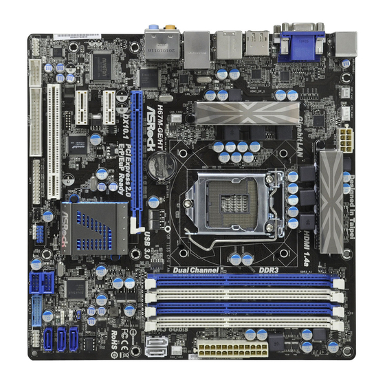
Page 2: Motherboard Layout
PCI Express 2.0 x1 Slot (PCIE2, White) SATA2 Connector (SATA2_4, Blue) PCI Express 2.0 x16 Slot (PCIE1, Blue) System Panel Header (PANEL1, White) Chassis Fan Connector (CHA_FAN2) Chassis Speaker Header (SPEAKER 1, White) USB 3.0 Header (USB_12_13, Light Blue) ASRock H67M-GE/THW Motherboard... - Page 3 See the table below for connection details in accordance with the type of speaker you use. TABLE for Audio Output Connection Audio Output Channels Front Speaker Rear Speaker Central / Bass Line In or (No. 9) (No. 6) (No. 5) Side Speaker (No. 8) ASRock H67M-GE/THW Motherboard...
- Page 4 “ok”. Choose “2CH”, “4CH”, “6CH”, or “8CH” and then you are allowed to select “Realtek HDA Primary output” to use Rear Speaker, Central/Bass, and Front Speaker, or select “Realtek HDA Audio 2nd output” to use front panel audio. ASRock H67M-GE/THW Motherboard...
-
Page 5: Package Contents
In case any modi cations of this manual occur, the updated version will be available on ASRock website without further notice. You may nd the latest VGA cards and CPU support lists on ASRock website as well. ASRock website http://www.asrock.com... -
Page 6: Specifications
- Supports HDCP function with DVI and HDMI ports - Supports Full HD 1080p Blu-ray (BD) / HD-DVD playback with DVI and HDMI ports - 7.1 CH HD Audio with Content Protection Audio (Realtek ALC892 Audio Codec) - Premium Blu-ray audio support ASRock H67M-GE/THW Motherboard... - Page 7 - 24 pin ATX power connector - 8 pin 12V power connector - Front panel audio connector - 3 x USB 2.0 headers (support 6 USB 2.0 ports) - 1 x USB 3.0 header (supports 2 USB 3.0 ports) ASRock H67M-GE/THW Motherboard...
- Page 8 Certifi cations - ErP/EuP Ready (ErP/EuP ready power supply is required) (see CAUTION 15) * For detailed product information, please visit our website: http://www.asrock.com WARNING Please realize that there is a certain risk involved with overclocking, including adjusting the setting in the BIOS, applying Untied Overclocking Technology, or using the third-party overclocking tools.
- Page 9 ASRock Extreme Tuning Utility (AXTU). ASRock website: http://www.asrock.com ASRock Instant Flash is a BIOS ash utility embedded in Flash ROM. This convenient BIOS update tool allows you to update system BIOS without entering operating systems rst like MS-DOS or Windows ®...
- Page 10 10. To experience intuitive motion controlled games is no longer only avail- able at Wii. ASRock AIWI utility introduces a new way of PC gaming operation. ASRock AIWI is the world's rst utility to turn your iPhone/iPod touch as a game joystick to control your PC games. All you have to do is...
- Page 11 Intel’s suggestion, the EuP ready power supply must meet the standard of 5v standby power ef ciency is higher than 50% under 100 mA current consumption. For EuP ready power supply selection, we recommend you checking with the power supply manufacturer for more details. ASRock H67M-GE/THW Motherboard...
-
Page 12: Cpu Installation
CPU surface is unclean or if there is any bent pin on the socket. Do not force to insert the CPU into the socket if above situation is found. Other- wise, the CPU will be seriously damaged. ASRock H67M-GE/THW Motherboard... - Page 13 Pin1 Pin1 alignment key 1155-Pin Socket orientation key notch 1155-Pin CPU For proper inserting, please ensure to match the two orientation key notches of the CPU with the two alignment keys of the socket. ASRock H67M-GE/THW Motherboard...
-
Page 14: Installation Of Cpu Fan And Heatsink
Please be noticed that this motherboard supports Combo Cooler Option (C.C.O.), which provides the exible option to adopt three dif- ferent CPU cooler types, Socket LGA 775, LGA 1155 and LGA 1156. The white throughholes are for Socket LGA 1155/1156 CPU fan. ASRock H67M-GE/THW Motherboard... -
Page 15: Installation Of Memory Modules (Dimm)
It is not allowed to install a DDR or DDR2 memory module into DDR3 slot; otherwise, this motherboard and DIMM may be dam- aged. Some DDR3 1GB double-sided DIMMs with 16 chips may not work on this motherboard. It is not recommended to install them on this motherboard. ASRock H67M-GE/THW Motherboard... -
Page 16: Installing A Dimm
DIMM if you force the DIMM into the slot at incorrect orientation. Step 3. Firmly insert the DIMM into the slot until the retaining clips at both ends fully snap back in place and the DIMM is properly seated. ASRock H67M-GE/THW Motherboard... -
Page 17: Installing An Expansion Card
Step 4. Align the card connector with the slot and press rmly until the card is completely seated on the slot. Step 5. Fasten the card to the chassis with screws. Step 6. Replace the system cover. ASRock H67M-GE/THW Motherboard... -
Page 18: Dual Monitor And Surround Display Features
VGA driver from our support CD to your system and restart your computer. D-Sub, DVI-D and HDMI monitors cannot be enabled at the same time. You can only choose the combination: DVI-D + HDMI, DVI-D + D-Sub, or HDMI + D-Sub. ASRock H67M-GE/THW Motherboard... - Page 19 F. Set the “Screen Resolution” and “Color Quality” as appropriate for the second monitor. Click “Apply” or “OK” to apply these new values. G. Repeat steps C through E for the diaplay icon identi ed by the number one, two, three and four ASRock H67M-GE/THW Motherboard...
- Page 20 HDTV set-top-boxes, as well as few entertainment PCs requires a secure connection to a compliant display. Due to the increase in manufacturers employing HDCP in their equipment, it is highly recommended that the HDTV or LCD monitor you purchase is compatible. ASRock H67M-GE/THW Motherboard...
- Page 21 Please be noted that the password, date, time, user default pro le, 1394 GUID and MAC address will be cleared only if the CMOS battery is removed. ASRock H67M-GE/THW Motherboard...
-
Page 22: Onboard Headers And Connectors
USB 2.0 Headers Besides four default USB 2.0 ports on the I/O panel, there (9-pin USB6_7) are three USB 2.0 headers on (see p.2 No. 23) this motherboard. Each USB 2.0 header can support two USB 2.0 ports. ASRock H67M-GE/THW Motherboard... - Page 23 This is an interface for print AFD# ERROR# PINIT# port cable that allows (25-pin LPT1) SLIN# convenient connection of printer (see p.2 No. 26) SPD7 devices. SPD6 ACK# SPD5 BUSY SPD4 SPD3 SLCT SPD2 SPD1 SPD0 STB# ASRock H67M-GE/THW Motherboard...
- Page 24 Connect to the power status indicator on the chassis front panel. The LED is on when the system is operating. The LED keeps blinking when the sys- tem is in S1 sleep state. The LED is off when the system is in S3/S4 sleep state or powered off (S5). ASRock H67M-GE/THW Motherboard...
- Page 25 CPU fan still can work successfully even without the fan speed control function. If you plan to connect the 3-Pin CPU fan to the CPU fan connector on this motherboard, please connect it to Pin 1-3. Pin 1-3 Connected 3-Pin Fan Installation ASRock H67M-GE/THW Motherboard...
- Page 26 HDMI_SPDIF header, providing SPDIF audio output to HDMI (2-pin HDMI_SPDIF1) VGA card, allows the system to (see p.2 No. 30) SPDIFOUT connect HDMI Digital TV/ projector/LCD devices. Please connect the HDMI_SPDIF connector of HDMI VGA card to this header. ASRock H67M-GE/THW Motherboard...
- Page 27 Unscrew the two screws from the Front USB 3.0 Put the USB 3.0 cable and the rear USB 3.0 Panel. bracket together. Step 4 Step 3 Screw the two screws into the rear USB 3.0 Put the rear USB 3.0 bracket into the bracket. chassis. ASRock H67M-GE/THW Motherboard...
-
Page 28: Driver Installation Guide
Using SATA / SATAII / SATA3 HDDs without NCQ function STEP 1: Set up BIOS. A. Enter BIOS SETUP UTILITY Advanced screen SATA Con guration. B. Set the option “SATA Mode” to [IDE]. ® STEP 2: Install Windows XP / XP 64-bit OS on your system. ASRock H67M-GE/THW Motherboard... -
Page 29: Installing Windows
STEP 1: Set Up BIOS. A. Enter BIOS SETUP UTILITY Advanced screen SATA Con guration. B. Set the option “SATA Mode” to [AHCI]. ® STEP 2: Install Windows 7 / 7 64-bit / Vista / Vista 64-bit OS on your system. ASRock H67M-GE/THW Motherboard... -
Page 30: Bios Information
It will display the Main Menu automatically if “AUTORUN” is enabled in your computer. If the Main Menu does not appear automatically, locate and double-click on the le “ASSETUP.EXE” from the BIN folder in the Support CD to display the menus. ASRock H67M-GE/THW Motherboard... - Page 31 1.1 パッケージ内容 ASRock H67M-GE/THW マザーボード: (Micro ATX フォームファクター : 9.6-in x 9.6-in, 24.4 cm x 24.4 cm) ASRock H67M-GE/THW クイックインストレーションガイド ASRock H67M-GE/THW サポート CD 2 x シリアル ATA (SATA) データケーブル(オプション) 1 x I/O パネルシールド 1 x USB 3.0 前面パネル 4 x HDD ねじ...
- Page 32 - HDMI 1.4a 搭載 Blu-ray Stereoscopic 3D 対応 - HDCP 機能、DVI ポートおよび HDMI ポートをサポート - 1080p Blu-ray (BD) / HD-DVD 再生サポート、DVI ポートおよび HDMI ポートをサポート オーディオ - 7.1 CH HD オーディオ ( コンテンツ保護付 ) (Realtek ALC892 オーディオ Codec) - Premium Blu-ray オーディオのサポー ASRock H67M-GE/THW Motherboard...
- Page 33 コンシューマー赤外線モジュールヘッダー x 1 - プリントポートヘッダ x 1 - COM ポートヘッダ x 1 - HDMI_SPDIF ヘッダー x 1 - 電源 LED ヘッダー x 1 - CPU/ シャーシ / 電源ファンコネクタ - 24 ピン ATX 電源コネクター - 8 ピン 12V 電源コネクター ASRock H67M-GE/THW Motherboard...
- Page 34 - ASRock Extreme チューニングユーティリティ (AXTU) ( 注意 8 参照 ) - インスタントブート - ASRock Instant Flash ( 注意 9 参照 ) - ASRock AIWI ( 注意 10 を参照 ) - ASRock APP ヱャージャー ( 注意 11 を参照 ) - SmartView ( 注意 12 を参照 ) - ハイブリッドブースタ...
- Page 35 7 64-bit / 7 / Vista 64-bit / Vista で使用できます。 マイク入力の場合、このマザーボードはステレオとモノラルモードをどちら もサポートします。オーディオ出力の場合、このマザーボードは 2 チャン ネル、4 チャンネル、6 チャンネルと 8 チャンネルモードをサポートしま す。正しい接続については、3 ページの表をチェックしてください。 ASRock Extreme Tuning Utility (AXTU) は、分かりやすいインター フェイスでさまざまなシステム機能を微調整するオールインワンツールで、 ハードウェアモニタ、ファンコントロール、オーバークロッキング、OC DNA、ES な どを含んでいます。ハードウェアモニタでは、システムの主要な読み込みを 示します。ファンコントロールでは、調整するファン速度と温度を示します。オー バークロッキングでは、CPU 周波数をオーバークロックして最適のシステムパ フォーマンスを出すことができます。OC DNA では、プロファイルとして OC 設...
- Page 36 直感的なモーションコントロールゲームは Wii だけのものではなくなりました。 ASRock AIWI ユーティリティによって、新しい PC ゲームの楽しみかたが広が ります。ASRock AIWI は、iPhone/iPod touch をジョイスティック代 わりに使用して PC ゲームをコントロールする世界初のユーティリティです。 ASRock AIWI ユーティリティを ASRock の公式 Web サイトまたは ASRock ソフトウェアサポート CD のいずれかからマザーボードにインストールし、無償の AIWI Lite を App ストアから iPhone/iPod touch にダウンロードするだ けという簡単さ。PC を Apple デバイスに Bluetooth(ブルートゥース)または...
- Page 37 ションを用意しています。すべての 775 と 1156 CPU ファンを使用できるわけ ではないことにご注意ください。 Energy Using Product(エコデザイン)の略語 EuP は完成システムの消 費電力を定義するために欧州連合により規制された条項です。 EuP に従っ て、管制システムの総 AC 電力はオフモード条件下で 1.00W 未満に抑える必 要があります。EuP 規格を満たすには、EuP 対応マザーボードと EuP 対応 電源が必要です。 Intel の提案に従い、EuP 対応電源装置は規格を満たす 必要があります、つまり 5v のスタンバイ電力効率は 100 mA の消費電流下 で 50% 以上でなければなりません。 EuP 対応電源装置を選択する場合、電 源装置製造元に詳細を確認するようにお勧めします。 ASRock H67M-GE/THW Motherboard...
- Page 38 梱包されていたバッグに収納してください。マザーボードをシャーシに取り 付ける為にネジをネジ穴に入れるときは、ネジを締め過ぎないようにしてく ださい。締めすぎるとマザーボードを傷つけます。 CPU インストレーション Intel 1155-LAND CPU の取り付けについては、 以下のステップに従ってください。 Load Plate Load Lever Socket Body Contact Array 1155 ピンソケットの概要 1155-LAND CPU をソケットに挿入する前に、CPU の表面が汚れていない か、ソケットに曲がったピンがないか確認してください。上の状況が見つ かった場合、CPU をソケットに無理に挿入しないでください。CPU がひど く損傷します。 ステップ 1. ソケットを開く : ステップ 1-1. レバーをフックまで押し下げて 保持タブを取り外します。 ASRock H67M-GE/THW Motherboard...
- Page 39 の方に向けます。ピン 1 と方向キー の 2 つの刻み目を探します。 方向キーの刻み目 位置合わせキー ピン 1 ピン 1 位置合わせキー 方向キーの刻み目 1155 ピンソケット 1155-LAND CPU 正しく挿入するために、CPU の 2 つの方向キーの刻み目がソケットの 2 つの 位置合わせキーに一致していることを確認してください。 ステップ 3-3. ソケットを完全に垂直移動するこ とによって、CPU をソケットに慎 重に配置します。 ステップ 3-4. CPU がソケット内部にあり、方向 キーに正しく一致していることを 確認します。 ASRock H67M-GE/THW Motherboard...
- Page 40 Press Down (4 Places) け、ロックします。残りのファスナー についても、上の操作を繰り返します。 ファスナーを時計回りに回転せずに押すと、ヒートシンクはマザーボード に固定できません。 ステップ 5. ファンヘッダをマザーボードの CPU ファンコネクタに説明します。 ステップ 6. ケーブルがファン動作の邪魔をしたり他のコンポーネントに触れな いように、余分なケーブルをタイラップでまとめます。 このマザーボードはコンボクーラーオプション (C.C.O.) に対応しており、 Socket LGA 775、LGA 1155 と LGA 1156 の 3 つの異なる CPU クーラー タイプを採用できる、柔軟なオプションを用意しています。白い貫通穴は Socket LGA 1155/1156 CPU 用です。 ASRock H67M-GE/THW Motherboard...
- Page 41 メモリーモジュール (DIMM) 取り付け H67M-GE/THW マザーボードには、240 ピン DDR3 (Double Data Rate 3) DIMM 用スロットが 4 カ所あり、デュアルチャンネルメモリーテクノロジーをサポートしています。 デュアルチャンネルコンフィギュレーションに関しては、常に同一 ( 同じメーカー、同じ速 度、同じサイズ、同じチップタイプ ) の DDR3 DIMM ペアを同じ色のスロットに取り付ける 必要が有ります。つまり、同一の DDR3 DIMM ペアをデュアルチャンネル A (DDR3_A1 お よび DDR3_B1、青色いスロット、2 ページの No.5 を参照 ) に挿入するか、同一の DDR3 DIMM ペアをデュアルチャンネル B (DDR3_A2 および DDR3_B2、白のスロット、2 ページ...
- Page 42 DIMM スロットが用意されています。 DIMM やシステムコンポーネントの着脱の前は電源が OFF になっているこ とを確認してください。 ステップ 1. 固定クリップを外側に押して DIMM スロットのロックを外します。 ステップ 2. DIMM のノッチがスロットの切れ目の位置に対応するように DIMM とスロット を合わせます。 notch break notch break DIMM は 1 つの正しい向きでのみ装着されるようになっています。DIMM を間違った向きでスロットに装着すると、マザーボードや DIMM に重大な 損傷がもたらされることがあります。 ステップ 3. 最後に、DIMM をスロットに挿入し、両端の固定クリップを所定の位置まで 戻して、DIMM をしっかり装着してください。 ASRock H67M-GE/THW Motherboard...
- Page 43 2.4 拡張スロット(PCI スロット、PCI Express スロット) H67M-GE/THW マザーボードには、PCI スロット 1 基、PCI Express スロット 3 基が備わっ ています。 PCI スロット : PCI スロットは、32 ビット PCI インターフェイスを持つ拡張 カードのインストールに使用します。 PCIE スロット : PCIE2 / PCIE3 (PCIE x1 スロット、白 ) は Gigabit LAN カー ド、SATA2 カードなど、PCI Express x1 レーン幅カードで使用さ...
- Page 44 シリアル ATAII コネクタ これら 3 本のシリアル ATAII SATA2_2 (SATAII)コネクタは内蔵スト SATA2_2: レーデバイスに使用する SATA ページ 2, アイテム 14 を参照 データケーブルに対応していま SATA2_3: SATA2_3 す。現在の SATAII インタフェー ページ 2, アイテム 15 を参照 スの最大データ転送速度は SATA2_4: 3.0 Gb/s です。 ページ 2, アイテム 16 を参照 SATA2_4 ASRock H67M-GE/THW Motherboard...
- Page 45 IntA_P2_D+ IntA_P2_D- 3.0 ポート 2 基に加え、USB 3.0 (19 ピン USB_12_13) IntA_P2_SSTX+ ヘッダが本マザーボードについてい ま ページ2, アイテム 19 を参照 IntA_P2_SSTX- す。この USB 3.0 ヘッダは USB 3.0 IntA_P2_SSRX+ IntA_P2_SSRX- Vbus ポート 2 基をサポートできます。 Vbus IntA_P1_SSRX- IntA_P1_SSRX+ IntA_P1_SSTX- IntA_P1_SSTX+ IntA_P1_D- IntA_P1_D+ ASRock H67M-GE/THW Motherboard...
- Page 46 MIC2_L ハイディフィニションオーディオはジャックセンシングをサポー トしますが、正しく機能するためにシャーシのパネルワイヤが HAD をサポートする必要があります。このマニュアルとシャー シのマニュアルの指示に従って、システムを取り付けてくださ い。 AC’97 オーディオパネルを使用する場合、次のように前面パ ネルのオーディオヘッダに取り付けてください。 Mic_IN (MIC) を MIC2_L に接続します。 Audio_R (RIN) を OUT2_R に、Audio_L (LIN) を OUT2_L に接続します。 Ground (GND) を Ground (GND) に接続しま す。 MIC_RET と OUT_RET はオーディオパネル専用です。 AC’97 オーディオパネルに接続する必要はありません。 ASRock H67M-GE/THW Motherboard...
- Page 47 押してコンピュータを再起動します。 PLED ( システム電源 LED): シャーシの前面パネルに付いている電源ステータスインジケータに接続しま す。LED は、システムが動作しているときに点灯します。LED はシステム が S1 スリープ状態のときに点滅します。システムが S3 または S4 スリープ状 態になるか、電源オフ (S5) になると、LED は消灯します。 HDLED ( ハードドライブアクティビティ LED): シャーシの前面パネルに付いているハードドライブアクティビティ LED に接続 します。LED は、ハードドライブがデータの読み込みまたは書き込み動作を しているときに点灯します。 前面パネルのデザインはシャーシによって異なります。前面パネルモジュール は、主に電源スイッチ、リセットスイッチ、電源 LED、ハードドライブア クティビティ LED、スピーカーなどから構成されています。シャーシの前面 パネルモジュールをこのヘッダに接続する際は、ワイヤとピンの割り当てが正 しく対応していることを確認してください。 ASRock H67M-GE/THW Motherboard...
- Page 48 (4 ピン CPU_FAN1) +12V アースピンに接続してください。 ページ2, アイテム 2 を参照 1 2 3 4 このマザーボードでは 4 ピン CPU ファン ( クワイエットファン ) がサポートされていますが、 ファン速度コントロール機能がない場合でも、3 ピン CPU ファンは正常に作動します。3 ピン CPU ファンをこのマザーボードの CPU ファンコネクタに接続しようとしている場合、 ピン 1-3 に接続してください。 接続されたピン 1-3 3 ピンファンのインストール ASRock H67M-GE/THW Motherboard...
- Page 49 (9 ピン COM1) ジュールをサポートします。 ページ2, アイテム 28 を参照 HDMI_SPDIF ヘッダ HDMI_SPDIF ヘッダは、SPDIF (2- ピン HDMI_SPDIF1) 音声出力を HDMI VGA カードに提 SPDIFOUT ページ2, アイテム 30 を参照 供し、システムで HDMI デジタル TV/ プロジェクタ /LCD デバイスに 接続できるようにします。HDMI VGA カードの HDMI_SPDIF コネク タを、このヘッダに接続してくださ い。 ASRock H67M-GE/THW Motherboard...
- Page 50 手順 手順 5 手順 手順 6 前面USB 3.0ケーブルをマザーボードのUSB これで前面USB 3.0パネルの 3.0ヘッダ(USB_12_13)に差し込みます。 使用準備は完了です。 背面USB 3.0ブラケットの取り付けガイド 手順 手順 1 手順 手順 2 前面USB 3.0パネルの2本のネジをはずします。 USB 3.0ケーブルと背面USB 3.0ブラケットを組み立てます。 手順 手順 4 手順 手順 3 背面USB 3.0ブラケットにネジを2本取り付け 背面USB 3.0ブラケットを筐体に ます。 取り付けます。 ASRock H67M-GE/THW Motherboard...
- Page 51 XP 64-bit ビット OS をインストールする場合、次のステップに従ってください。 NCQ およびホットプラグ機能を搭載しない SATA / SATAII / SATA3 HDD デバイスを 使用する ステップ 1: セットアップ BIOS。 A. BIOS セットアップユーティリティ、詳細画面、SATA 構成に入ります。 B. 「SATA Mode」を [IDE] に設定し。 ® ステップ 2: システムに Windows XP / XP 64- ビット OS をインストールします。 ASRock H67M-GE/THW Motherboard...
- Page 52 NCQ およびホットプラグ機能を搭載した SATA / SATAII / SATA3 HDD デバイスを使 用する ステップ 1: セットアップ BIOS。 A. BIOS セットアップユーティリティ、詳細画面、SATA 構成に入ります。 B. 「SATA Mode」を [AHCI] に設定し。 ステップ 2: システムに Windows ® 7 / 7 64- ビット / Vista / Vista 64 ビ ト OS をインストールします。 ASRock H67M-GE/THW Motherboard...
- Page 53 7 / 7 64-bit / Vista / Vista bit / XP / XP 64-bit といった様々なマイクロソフト ウインドウズ オペレーティングシ ステムをサポートします。マザーボードに付属しているサポート CD はマザーボードの特徴 を有効にするために必要なドライバやユーティリティを含んでいます。サポート CD を使用 するには、CDROM ドライブに CD を挿入してください。AUTORUN 機能が有効な場合、自 動的にメインメニュウが立ち上がります。AUTORUN 機能が無効な場合、サポート CD 内の BIN フォルダにある ASSETUP.EXE をダブルクリックすることにより、メインメニュウが立ち 上がります。 ASRock H67M-GE/THW Motherboard...
-
Page 54: Installing Os On A Hdd Larger Than 2Tb
Installing OS on a HDD Larger Than 2TB ® This motherboard is adopting UEFI BIOS that allows Windows OS to be installed on a large size HDD (>2TB). Please follow below procedure to install the operating system. ® 1. Please make sure to use Windows Vista 64-bit (with SP1 or above) or ®...
Need help?
Do you have a question about the H67M-GE/THW and is the answer not in the manual?
Questions and answers