2N EasyRoute User Manual
Umts data and voice gateway
Hide thumbs
Also See for EasyRoute:
- User manual (102 pages) ,
- How-to (6 pages) ,
- Quick setup manual (3 pages)

Related Manuals for 2N EasyRoute


Summary of Contents for 2N EasyRoute
-
Page 1: User Manual
® EasyRoute UMTS Data and Voice Gateway User Manual Version 1.06 www.2n.cz... - Page 2 2N TELEKOMUNIKACE administers the FAQ database to help you quickly find information and to answer your questions about 2N products and services. On faq.2n.cz you can find information regarding products adjustment and instructions for optimum use and procedures „What to do if...“.
-
Page 3: Table Of Contents
1. Product Overview ............. 5 Product Description ....................6 Basic Features ......................6 ® Advantages of 2N EasyRoute Use ................6 Safety Precautions ....................... 7 Changes in Documentation ..................9 Terms and Symbols Used ..................10 Symbols in Manual ..................... 10 Future Functions ...................... - Page 4 4. Function and Use ............81 Voice Function ......................82 Outgoing Call ......................82 Incoming Call ......................82 Automatic Call (BabyCall) ..................82 16 or 12 kHz Tariff Pulses ..................83 Ethernet Switch and WiFi Interface ................. 84 Static Network Configuration ..................84 Dynamic Network Assignment ..................
-
Page 5: Product Overview
Product Overview ® In this section, we introduce the 2N EasyRoute product, outline its application options and highlight the advantages following from its use. This chapter also includes safety instructions. Here is what you can find in this section: Product Description... -
Page 6: Product Description
Product Description 1.1 Product Description ® The 2N EasyRoute GSM/UMTS gateway is a new product, which has been developed and manufactured to provide the maximum utility value, quality and reliability. We ® hope you will be fully satisfied with 2N EasyRoute for a long time. -
Page 7: Safety Precautions
RF electromagnetic field radiation while telephoning. Full GSM/UMTS coverage ® EasyRoute supports all GSM bands (1900, 1800, 900, 850MHz). EasyRoute is available in version for all used UMTS bands (2100 1900, 900, 850MHz). Fast Ethernet switch ® EasyRoute provides a 4-port Fast Ethernet switch for you to connect all the required devices (using an external switch for a larger port extension). - Page 8 Any mobile telephone use prohibition based on RF energy radiation applies to ® EasyRoute too. ® EasyRoute may disturb the function of TV sets, radio sets and PCs. ® Warning! 2N EasyRoute contains components that may be swallowed by small children (SIM card, antenna, etc.).
-
Page 9: Changes In Documentation
The User Manual applies to FW Version 2.02. (IPsec, PPPoE) Caution The manufacturer is committed to meeting customers’ requirements by ® improving the firmware. For the latest 2N EasyRoute processor firmware and the User Manual see www.2n.cz. ® For a detailed description of the 2N EasyRoute firmware upgrade refer to ®... -
Page 10: Terms And Symbols Used
Note Routines or advice for efficient use of the device. Future Functions ® The grey-marked text in this document designates the 2N EasyRoute functions that are under preparation or development at present. Caution In future, ERF will be replaced with VoIP in the FAX version name. Thus, ®... -
Page 11: Description And Installation
Description and Installation ® This section describes the 2N EasyRoute product and its installation. Here is what you can find in this section: Description Before You Start Mounting Telephone Line Connection... -
Page 12: Description
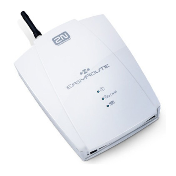
EasyRoute consists of a plastic-encased GSM/UMTS gateway, removable antenna and telephone network/LAN connecting cables. ® The 2N EasyRoute status is indicated by the LED on its front side. All possible states are described in the following figure. Figure 2.1 ®... -
Page 13: Before You Start
EasyRoute on sites exposed to direct solar radiation or near heat sources. ® EasyRoute is designed for indoor use. It may not be exposed to rain, flowing water, condensed moisture, fog, etc. ® EasyRoute may not be exposed to aggressive gas, acid vapours, solvents, etc. -
Page 14: Mounting
The antenna should be located within the same building as 2N EasyRoute. SIM Card Installation ® Release the safety pin and open the SIM cardholder on the 2N EasyRoute backside. Insert the SIM card and click the holder back into position. Figure 2.3... -
Page 15: Wall Mounting
EasyRoute Wall Mounting Power Supply ® EasyRoute is fed with 10–16V DC. Where a source other than the included power ® supply adapter is used, the voltage range and polarity shown on the 2N EasyRoute power supply connector have to be maintained... -
Page 16: Telephone Line Connection
2.4 Telephone Line Connection PBX Connection ® Connect 2N EasyRoute to a vacant CO line of your PBX. Configure your PBX in such a manner that UMTS and GSM (VoIP for EFR) outgoing calls are routed to ® EasyRoute. ®... -
Page 17: N Easyroute Configuration
® EasyRoute Configuration ® This section describes configuration of the 2N EasyRoute product. Here is what you can find in this section: ® EasyRoute Configuration Table of Programmable Parameters... -
Page 18: Easyroute Configuration
3.1 2N EasyRoute Configuration ® ® EasyRoute is configured via a user-friendly network web interface. 2N EasyRoute is factory set to make administration as easy as possible. PC Connection You have received a Fast Ethernet cable for PC connection. The DHCP server is active in the gateway and assigns your PC an IP address ranging from 192.168.1.100 to... - Page 19 2N® EasyRoute Configuration Initial username: User Password: The User is authorised to work with SMS, access the call register and manage the User password. Caution We recommend that you should change the web access username and password after the first power up!
-
Page 20: Table Of Programmable Parameters
Table of Programmable Parameters 3.2 Table of Programmable Parameters ® All programmable parameters of 2N EasyRoute are listed in this subsection. The unit ® used, description of 2N EasyRoute's behaviour upon a change, setting options, the setting step and the default (initialisation) setting are included for each parameter. - Page 21 Table of Programmable Parameters Icons There are three navigation icons in the right-hand upper corner of the screen for you to access the SETUP, SMS and STATUS menus quickly and easily. The following basic control buttons are located in the right-hand bottom corner of the configuration interface: Refresh –...
-
Page 22: Status Menu
Table of Programmable Parameters Connect – connect to the UMTS network manually. Disconnect – disconnect from the UMTS network manually. Sale – generate a new HotSpot ticket. Menu The left-hand section of the screen shows menus that can be opened by a mouse click. The WIZARD menu will help you configure the basic gateway functions quickly. -
Page 23: Connection Type
(e.g. requires the PIN), the Limited service message is displayed. Connection type ® Displays the type of 2N EasyRoute connection to a wireless network (GSM, EDGE, GPRS, UMTS, HSDPA/HSUPA, etc.). FUP limit Displays the counter capacity according to FUP parameters. - Page 24 Displays the current telephone number for the registered line. Registrar Displays the current server to which the 2N® EasyRoute SIP account should register. Proxy Displays the current server via which the 2N® EasyRoute - VoIP provider SIP communication takes place. Others WLAN Gateway WiFi network state.
-
Page 25: Wizard Menu
PIN correctly before inserting a new SIM card. Now click on Apply to confirm the currently made changes. Having done this, you move to the next Wizard window and 2N® EasyRoute will, if the PIN is correct, log in to the wireless network. - Page 26 (Service Set Identifier) is the WiFi identifier that is sent to users. It is a unique network identifier in the given space. System sets security to the 2N® EasyRoute WiFi interface. The available security levels include WEP, WPA, WPA2 and WPA+WPA2. The WiFi security...
-
Page 27: Calls Menu
The WiFi security Key consists of a sequence of alphanumeric characters, or hexadecimal symbols as defined in the Key format. Having set the values, click on Apply. Now your 2N® EasyRoute gateway is ready for basic operation. Refer to the subsections below or the HOW TO manuals for details on all programmable parameters. -
Page 28: Sms Menu
Table of Programmable Parameters Missed The menu gives an overview of all missed incoming gateway calls. The meanings of the menu columns correspond to those in the All section. To move between the pages use the page numbers in the bottom part of the screen. Use the >> symbol to jump onto the oldest call. -
Page 29: Setup Menu > Cellular
Type Type of the SIM card inserted. Options: SIM, USIM, or Unknown when ® EasyRoute cannot identify the SIM card. Status Status of the SIM card inserted. Some statuses are rather rare and so the most important SIM card statuses are mentioned only. - Page 30 The PIN is displayed not in the text format but as a dot only. Remember Select Remember to make 2N® EasyRoute save the PIN after a successful SIM login and enter the same automatically upon the next start. A wrong PIN is not remembered.
- Page 31 Mobile Network Code (MNC). Use the parameter to select the provider to ® which 2N EasyRoute with a SIM should log for roaming purposes. Just select a provider from the list of available networks and the provider code will be set automatically.
- Page 32 Displays the name of the provider to which the SIM is logged in. If the SIM card cannot log in to a network (e.g. requires the PIN), the Limited service message is displayed. Connection type ® Displays the type of 2N EasyRoute connection to a wireless network (GSM, EDGE, GPRS, UMTS, HSDPA/HSUPA, etc.). Internet...
- Page 33 To display the internal APN database, click on the List link. The currently used data are highlighted in the table. If no table row is highlighted, ® EasyRoute has no data on your provider. In that case, enter the data manually. LCP echo interval [0 – 3600 s] Set the timeout after which the LCP echo should be sent.
- Page 34 Table of Programmable Parameters Disconnection notification [1 – 3600s] A notification SMS is sent when the defined period of time elapses. Errors must come in a sequence to be considered. This means that the first correct attempt clears the counter even if the next one is wrong again. DNS1/DNS2 The IP address of the DNSs used as assigned by the provider upon network login.
-
Page 35: Noise Suppression
Table of Programmable Parameters data transmitted in the given direction. The third parameter sets the amount of data to be transmitted. The fourth parameter defines units. Time Enable that the preset time limit should be applied to Internet connection. The second parameter is for information only and displays the current time of connection use. - Page 36 Table of Programmable Parameters Headset Car kit (AEC) – for noisy environments Speaker RX AVC (Automatic Volume Control) Enable/disable the automatic setting of the receiving signal volume. RX AGC (Automatic Gain Control) Enable/disable the automatic setting of the signal receive gain. TX AGC (Automatic Gain Control) Enable/disable the automatic setting of the signal transmit gain.
- Page 37 Table of Programmable Parameters Phone number to SMS notification Set up to 5 nine-digit numbers (e.g. 765123456) to which notification SMS on the ® EasyRoute state should be sent. All generated SMS will be sent to all the numbers entered here. Balance Enable Enable USSD commands to be sent.
-
Page 38: Setup Menu > Telephony
SETUP Menu > Telephony SLIC - Basic Version This section is split into two subsections to distinguish the two available ® EasyRoute versions – the basic version (standard, ER version) and the FAX version (ERF). Dialling Time to dial ®... - Page 39 FSK/ETSI receiving device on your telephone line. Setting options: Disable ® EasyRoute restricts CLI towards the telephone line. FSK during ringing ® EasyRoute transmits the FSK-based CLI according to the ETSI EN 300 659 standard during ringing.
- Page 40 Table of Programmable Parameters Replace ‘+’ by If this parameter is enabled, the ‘+’ character is replaced with the defined string in the international prefix of the CLI. It is because the ‘+’ character can neither be transmitted by the FSK protocol nor dialled in the DTMF format from a terminal. Setting options: 0–15 characters (0–9, *, #) Signalling...
- Page 41 Table of Programmable Parameters 10 nF Two-wire Impedance Synthesis Adjust the telephone line to the FXS interface. Setting options: 600 Ohm 900 Ohm 600 Ohm + 2.16 µF 900 Ohm + 2.16 µF 270 Ohm + 750 Ohm || 150 nF 220 Ohm + 820 Ohm || 120 nF 220 Ohm + 820 Ohm || 115 nF 370 Ohm + 620 Ohm || 310 nF...
- Page 42 Minimal onhook time Set the minimum line current discontinuation to be evaluated as hang-up by ® EasyRoute. If shorter, the discontinuation is ignored by the gateway. Minimal offhook time Set the minimum time interval after which the off-hook state is detected.
- Page 43 FSK/DTMF (ETSI) receiving device on your telephone line. Setting options: Disable ® EasyRoute restricts CLI towards the telephone line. ETSI FSK ® EasyRoute transmits CLI using FSK (Frequency Shift Keying) to a telephone line.
- Page 44 Table of Programmable Parameters ETSI DTMF ® EasyRoute transmits the received CLI using the DTMF (Dual Tone MultiFrequency) signalling to a telephone line. Default setting: ETSI FSK Enable or disable the echo cancelling function (Line Echo Canceller). RX gain Set the gain for the receive path.
- Page 45 User agent Set the name to be displayed to the called subscriber. Local port ® Set the port to be used for SIP communication by 2N EasyRoute. RTP port base Set the port for RTP stream sending. RTP port count Set the range of the RTP ports to be used.
- Page 46 So do not change the default values of Codec 5 for the time being (Unused). SIP > Account Enable registration Enable 2N® EasyRoute to register the selected account to the VoIP provider. Registrar Set the IP address or domain name for the registrar server. Proxy ®...
- Page 47 Set the time intervals for stimulation packet sending. The Flood function has been developed to compensate the initial data ® transmission slowness in the UMTS network. Thus, 2N EasyRoute sends stimulation packets at preset intervals to achieve the optimum data flow at initial stages of bulk data transmissions.
- Page 48 Set the maximum UDP/TCP datagram size. Default setting: 200 B Error correction Define how to correct the errors in the FAX messages to be transmitted. Setting options: Redundancy ® EasyRoute uses the Redundancy Error Correction. ® EasyRoute uses the Forward Error Correction.
- Page 49 Default setting: Disabled ® Each network to which 2N EasyRoute is connected may behave in a different way. If you have FAX transmission problems, you can probably resolve them by setting the above mentioned parameters properly. Output signal power Set the output signal level for FAX modulation.
- Page 50 Table of Programmable Parameters Default setting: Control transmission redundancy (V.21) Set the UDPTL protocol parameters. Setting options: 0 - 4 Default setting: Duplication of T.30 indicator Set how many times the indicator (CNG, CED, e.g.) should be copied. Setting options: 0 - 4 Default setting: Packets for FEC...
-
Page 51: Routing Mode
The lower screen menu helps you set the mode of the routing table use. Setting options: ® All to GSM: 2N EasyRoute routes all calls to the GSM network regardless of the routing table settings. ® All to VOIP: 2N EasyRoute routes all calls to the VoIP network regardless of the routing table settings. - Page 52 VoIP ® Only in fax version of 2N EasyRoute. Use this parameter to redirect calls with the prefixes specified on the given row to VoIP network. Length Use the Length parameter to define the expected length of a number including its prefix for the given row.
-
Page 53: Setup Menu > Hotspot
Table of Programmable Parameters Refer to S. 4 of this User Manual for table setting examples. SETUP Menu > Hotspot Hotspot is a function allowing a user to access, on a time or data (FUP) basis, the Internet with the aid of a valid access password (ticket). It is intended for Internet coffee bars and similar public facilities. - Page 54 Table of Programmable Parameters Ticket valid time Set the time period during which the connection may be activated. After this time period passes, the ticket becomes invalid. Setting options: 1 minute to 60 days Enable calculation Enable the connection cost calculation and ticket registration. Unit price (per hour) Set the unit price for the ticket cost calculation.
- Page 55 Table of Programmable Parameters Tickets Overview of the generated tickets and their use – valid tickets only. History Overview of the generated tickets and their use – including used and invalid tickets. This menu allows an export of records to Excel for future use. It gives an overview of prices of sold tickets.
- Page 56 Table of Programmable Parameters Ticket valid time Set the time period during which the connection may be activated. After this time period passes, the ticket becomes invalid. The value predefined in the Basic menu is used by default. Setting options: 1 minute to 60 days Ticket preview Displays the parameters of the ticket to be generated and information on the last...
-
Page 57: Setup Menu > Network
Valid network address of the DNS LAN1 – LAN4/WAN The interfaces connected are displayed. If you connect the cable to the 2N® EasyRoute switch, you get the connection rate and type for each port. If you enable the WAN port, LAN4 is converted into WAN. - Page 58 Even if both the options are selected and saved in the database, the option that is programmed is applied. Static ® IP address assigned to your 2N EasyRoute WAN port as communicated by your Internet provider or network administrator. Subnet ® Mask of the network where your 2N EasyRoute gateway will be operating as communicated by your Internet provider or network administrator.
- Page 59 DNS1, DNS2, IP These parameters cannot be programmed. They are for information only and ® provide the data that 2N EasyRoute received from the ADSL provider after authorisation. Note LCP echo is a function of the PPP demon, which is responsible for connection to the provider (UMTS/PPPoE).
- Page 60 Set the maximum size of packets for a wireless network. Setting options: 0–2,346 B WLAN > Security System ® Set the 2N EasyRoute WiFi interface security system. Setting options: WPA2 WPA+WPA2 Key format Set the WiFi interface security key format. Setting options:...
- Page 61 Table of Programmable Parameters The WiFi security key consists of a sequence of alphanumeric characters or hexadecimal symbols (as defined in the Key format). Setting options: For WEP key: Enter 5, 13 or 16 alphanumeric characters, or 10, 26 or 32 hexadecimal symbols.
- Page 62 Specify how the user should get connected to the Internet. If you select Manual ® connection, 2N EasyRoute will not connect to the Internet until you push the Connect button in the STATUS menu. Caution To make the system work properly, make sure that: The WAN port is set and connected properly.
- Page 63 Varování ® Be sure to disable this protection when you access 2N EasyRoute remotely via the WAN port to avoid gateway response failures. Check ICMP Enable/disable the check of the ICMP packets passing through the gateway.
- Page 64 Table of Programmable Parameters Firewall > Port Forwarding Used for routing packets coming from the Internet to specified ports, routed to specified internal addresses and ports. The function is often designated as the static NAT. Input Define the port to be forwarded. If a packet routed to this port comes to the gateway, it is automatically forwarded to the destination specified in the Target column.
-
Page 65: Setup Menu > Services
Table of Programmable Parameters SETUP Menu > Services DHCP... - Page 66 Gateway IP address of the currently used gateway. The item can include either an IP ® address defined by the user in the LAN menu or the 2N EasyRoute IP address. DNS1/DNS2 IP addresses of the currently used DNSs. The item can include the servers defined by the user in the LAN menu or assigned by the GSM provider, or the ®...
- Page 67 EasyRoute DNS. Enable cache ® Enable/disable the 2N EasyRoute cache memory for DNS entries. Cache low Minimum number of DNS entries in the cache memory. Cache high Maximum number of DNS entries in the cache memory. When this limit is reached, entries are deleted down to the minimum number of entries as provided by the Cache low parameter.
-
Page 68: Host Name
Internet domain in real time. The DDNS allows you to use a stable DNS name instead of a variable IP address. Enable ® Enable/disable the use of the dyndns.org server by 2N EasyRoute. Username Enter the username for DDNS connection. The user must be registered with the dyndns.org server. - Page 69 Thu Jan 1 00:00:00 2009 after every gateway restart. SSH - Basic The SSH (Secure Shell) protocol provides encoded connection with the SSH- ® supporting servers. 2N EasyRoute always works in the client mode.
- Page 70 Table of Programmable Parameters Enable SSH client Enable the use of the SSH protocol. SSH server name ® Enter the name of the SSH server to which 2N EasyRoute is to be connected. Client public key ® A key generated by 2N EasyRoute (represented by a code), which can be stored on a disk.
- Page 71 Set the maximum server response time. Max failures before re-connect Set the maximum count of attempts before the Peer-to-Peer Protocol (PPP) is ® restarted in 2N EasyRoute. Setting options: 0 to 1,000 (0 – no restart, 0 is not displayed) Notification limit A notification SMS is sent when the set value is reached.
- Page 72 No data are transmitted in the main mode. 2N® EasyRoute uses the ISAKMP for this phase. The Quick mode is used for data transmission, which is the essence of IPsec.
-
Page 73: Nat Traversal
Aggressive. Identifier Define the identifier for authorisation at the opponent’s. Options: Address, FQDN or USER FQDN. The PSK table setting is verified. NAT Traversal Enable the use of NAT: 2N® EasyRoute always finds the whole route and use of NATs. - Page 74 IPsec - Manual Caution Setting the IPsec function in this menu is rather difficult. Refer to the dedicated IPsec HOW TO manual at www.2n.cz or on the enclosed CD for more details. IPsec – PSK In this menu set the pre-shared security keys. The keys are included in the table below according to the identifier settings in the VPN menu.
-
Page 75: Setup Menu > System
Push this button to save the new settings. (Button is placed bottom right.) Firmware This menu is used for downloading the current gateway firmware, module or bootloader versions into 2N® EasyRoute. Module Information on the module version and date of issue. -
Page 76: Time Zone
Table of Programmable Parameters Firmware 0/1 Information on the firmware version, date of issue and downloading instance number (behind the ‘#’ symbol). An Active note is added to one of the firmware instances to indicate the currently used one. The new firmware is stored automatically, replacing the preceding one, and becomes active after restart. - Page 77 Current gateway system time depending on the SNTP, time zone and daylight saving time settings. Configuration Operation This choice enables import/export of 2N ® EasyRoute setinngs or SMS databaze. The operation is done after clicking on the Save button placed right bottom on the screen. File to import Select path to the file with configuration or SMS database.
- Page 78 Table of Programmable Parameters IMSI lock MSI (International Mobile Subscriber Identity) is a unique identification code for SIM cards. Using the IMSI lock, the gateway locks a selected SIM card, rejecting the other ones. Capture This menu helps you capture events on your gateway network elements. Packets are saved into files dimensioned by the Pool parameter according to the Filter and Interface selection.
-
Page 79: System Log
System reports from the 2N Telekomunikace program module (registrations, calls, faxes, etc.). Note The Event reporter is identical for either 2N® EasyRoute version. The 2N® EasyRoute and System logs are only supported in the basic version. The other logs are useless because the functions are not supported. -
Page 81: Function And Use
Function and ® This section describes the basic and extending functions of the 2N EasyRoute product. Here is what you can find in this section: Voice Function Ethernet Switch and WiFi Interface SIM Card PIN Protection FAX Sending/Receiving... -
Page 82: Voice Function
® antenna connected and 2N EasyRoute logged-in to the GSM network – the GSM network LED is flashing and you can hear the dialtone upon off-hook. A VoIP account is configured and the gateway is logged in to the provider in the ERF version. -
Page 83: Or 12 Khz Tariff Pulses
16 or 12 kHz Tariff Pulses ® EasyRoute has a tariff pulse transmitter. You can use the pulses for outgoing call ® metering and/or billing. 2N EasyRoute offers pseudo tariff metering only – its tariff pulses do not correspond to the provider’s call tariffs but are transmitted according to... -
Page 84: Ethernet Switch And Wifi Interface
Ethernet Switch and WiFi Interface 4.2 Ethernet Switch and WiFi Interface ® EasyRoute is equipped with a 4-port Fast Ethernet switch and a WiFi card. These ® interfaces allow a PC/LAN to be connected to 2N EasyRoute. A proper network address and mask settings are needed for correct LAN and Internet connections. -
Page 85: Sim Card Pin Protection
PIN is entered automatically upon every gateway power up. Automatic PIN Entering ® You do not have to enter the PIN upon power up if it is stored in the 2N EasyRoute memory - it is entered automatically. This function is convenient in case of power ®... -
Page 86: Fax - Erf
® connected and 2N EasyRoute logged in to a GSM network – the UMTS/GSM network indicator is flashing and, having seized the line, you hear the dialtone. Suppose the VoIP account is configured and the gateway is logged in to a T.38 fax transmission supporting VoIP provider. -
Page 87: Incoming Fax
FAX - ERF transmission you can hear the fax machine ‘beeping’. Beeping is normal; it is a sequence of predefined T.38 tones. The Line indicator keeps shining during the whole FAX transmission process. Typically, you are informed of your FAX transmission success or failure through a success or failure report printout. -
Page 89: Technical Parameters
Technical Parameters ® This section describes the technical parameters of the 2N EasyRoute product. -
Page 90: Technical Parameters
Technical Parameters 5.1 Technical Parameters 850 / 1 900 / 2 100 MHz UMTS WCDMA / HSDPA MC8790V 850 / 900 MHz EGSM / GPRS / EDGE 1 800/1 900 MHz GSM / GPRS / EDGE 2 100 MHz UMTS WCDMA / HSDPA MC8791V 850 / 900 MHz EGSM / GPRS / EDGE 1 800/1 900 MHz GSM / GPRS / EDGE... -
Page 91: Power Supply
Technical Parameters Power Supply Mains supply 100–240 V/12 V; 2A adapter DC power supply 10 to 16V DC Standby 350 mA Voice call 450 mA 12 V consumption Data connection 400 mA Voice and data 500 mA Supply connector DC Jack 2.1 mm Phone Interface –... -
Page 92: Ethernet Switch
Technical Parameters Calling line identification CLIP during ringing according to ETSI FSK / DTMF Ethernet Switch Interface type 4-port Fast Ethernet switch 100Mbps Connector RJ-45 WiFi Bandwidth 2,5 / 5 GHz Standard 802.11a/b/g Others Dimensions (w/o 170×130×45 mm connectors) 0 C to 45 C Operating temperature Operating status signalling 3 LEDs (On;... -
Page 93: Supplementary Information
Supplementary Information This section provides supplementary information on the product. Here is what you can find in this section: Directives, Laws and Regulations Troubleshooting List of Abbreviations General Instructions and Cautions... -
Page 94: Directives, Laws And Regulations
Directives, Laws and Regulations 6.1 Directives, Laws and Regulations ® EasyRoute conforms to the following directives, laws and regulations: Act No. 22/1997 Coll. Of January 24, 1997 on technical requirements of products and amendments to some laws Directive 1999/5/EC of the European Parliament and of the Council, of 9 March 1999 –... -
Page 95: Troubleshooting
Troubleshooting 6.2 Troubleshooting For tips for the solution of other potential problems see faq.2n.cz. ´ No LED is on after power up. u Check the power supply. ´ ® EasyRoute is not logging into the GSM network. u Check the SIM card. -
Page 96: List Of Abbreviations
List of Abbreviations 6.3 List of Abbreviations APN (Access Point Name) Necessary for the GPRS service. CLIP (Calling Line Identification Presentation) CSD (Circuit Switched Data) DTMF (Dual Tone MultiFrequency) Tone dialling. FSK (Frequency Shift Keying) A transmission protocol using variable signal frequencies for logic level encoding. -
Page 97: General Instructions And Cautions
General Instructions and Cautions 6.4 General Instructions and Cautions Please read this User Manual carefully before using the product. Follow all instructions and recommendations included herein. Any use of the product that is in contradiction with the instructions provided herein may result in malfunction, damage or destruction of the product. -
Page 98: Electric Waste And Used Battery Pack Handling
General Instructions and Cautions Electric Waste and Used Battery Pack Handling Do not place used electric devices and battery packs into municipal waste containers. An undue disposal thereof might impair the environment! Deliver your expired electric appliances and battery packs removed from them to dedicated dumpsites or containers or give them back to the dealer or manufacturer for environmental-friendly disposal. - Page 99 2N TELEKOMUNIKACE a.s. Modřanská 621, 143 01 Prague 4 Tel.: +420 261 301 500, Fax: +420 261 301 599 E-mail: sales@2n.cz Web: www.2n.cz 1571v1.06...