Advertisement
Model No. 831.15629.0
Serial No.
Write the serial number in the
space above for reference.
Serial Number Decal (under seat)
• Assembly
• Adjustments
• Part List and Drawing
CAUTION
Read all precautions and instruc-
tions in this manual before using
this equipment. Save this manu-
al for future reference.
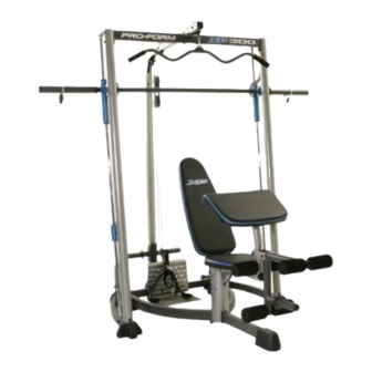
WEIGHT BENCH EXERCISER
Sears, Roebuck and Co., Hoffman Estates, IL 60179
User's Manual
Advertisement
Table of Contents

Subscribe to Our Youtube Channel
Related Manuals for Pro-Form XP 300


Summary of Contents for Pro-Form XP 300
- Page 1 Model No. 831.15629.0 Serial No. WEIGHT BENCH EXERCISER Write the serial number in the space above for reference. User’s Manual Serial Number Decal (under seat) • Assembly • Adjustments • Part List and Drawing CAUTION Read all precautions and instruc- tions in this manual before using this equipment.
-
Page 2: Table Of Contents
TABLE OF CONTENTS WARNING DECAL PLACEMENT ............. 2 IMPORTANT PRECAUTIONS . -
Page 3: Important Precautions
IMPORTANT PRECAUTIONS WARNING: To reduce the risk of serious injury, read the following important precautions before using the weight bench. 1. Read all instructions in this manual and all 10. Always make sure that the backrest knob is warnings on the weight bench before using fully inserted into the backrest frame before the weight bench. -
Page 4: Before You Begin
BEFORE YOU BEGIN Thank you for selecting the versatile PROFORM ® reading this manual, call 1-800-4-MY-HOME ® 300 weight bench. The weight bench is designed to (1-800-469-4663). To help us assist you, please note help develop every major muscle group of the body. -
Page 5: Assembly
ASSEMBLY • Tighten all parts as you assemble them, unless Make Things Easier for Yourself instructed to do otherwise. Everything in this manual is designed to ensure • For help identifying small parts, use the PART that the weight bench can be assembled suc- IDENTIFICATION CHART. - Page 6 2. Attach the Bench Foot (15) to the Seat Base (1) with two M4 x 16mm Self-tapping Screws (91) and two M4 Washers (84). 3. Insert two M10 x 100mm Screws (26) up through the Base Plate (34), and the Seat Base (1), and the Right and Left Seat Bases (2, 3).
- Page 7 5. Attach the Backrest (11) to the Backrest Frame (8) with four M6 x 15mm Button Screws (17). 6. Grease the M10 x 87mm Button Bolt (94). Attach the Backrest Frame (8) to the Seat Frame (5) with the Bolt and an M10 Nylon Locknut (77). Do not overtighten the Locknut;...
- Page 8 8. Attach the Seat (12) to the Seat Frame (5) with four M6 x 63mm Button Screws (92) and four M6 Washers (81). 9. Insert a Pad Tube (10) into the Leg Lever (6). Slide two Foam Pads (14) onto the Pad Tube. Assemble the other two Pad Tubes (10) to the Leg Lever (6) and the Seat Frame (5) in the same manner.
- Page 9 11. Attach the Left Rack Base (37) to the Center Rack Base (39) with two M10 x 67mm Bolts (86), an M10 Washer (80), and an M10 Nylon Locknut (77). Do not tighten the Bolts. Repeat this step with the Right Rack Base (38). 12.
- Page 10 14. Insert the M10 x 20mm Bolt (89) into the Weight Carriage (42) from the side shown. Slide the Weight Carriage Stop (58) onto the Rear Upright (41). Slide the Weight Carriage (42) onto the Rear Upright. 15. Attach a Guide Rod (46) to the Left Rack Base (37) with an M8 x 53mm Bolt (9), two M8 Washers (83), an 11mm x 8mm Spacer (82), and an M8 Nylon Locknut (78).
- Page 11 17. Attach a Front Upright (43) to the Right Rack Base (38) with two M10 x 82mm Bolts (85), two M10 Washers (80), and an M10 Nylon Locknut (77). Do not tighten the Bolts. Attach the Front Upright (43) to the right Guide Rod (46) with an M10 x 25mm Bolts (88).
- Page 12 20. Orient the Locking Bar (50) as shown. Slide the Barbell (51) through the Left Barbell Guide (52), the Locking Bar, and the Right Barbell Guide (53). Make sure that the Barbell is centered in the Barbell Guides. Engage the Locking Bar into the Uprights (43) at the lowest position.
- Page 13 24. Route the Cable (61) under a Pulley (63). Attach the Pulley, a Cable Trap (66), and two Half Finger Guards (65) to the two Pulley Plates (35) with an M10 x 50mm Bolt (79) and an M10 Nylon Locknut (77).
-
Page 14: Adjustments
29. Attach the Cable (61) to the Rear Rack Base (40) with an M10 x 67mm Bolt (86), two M10 Washers (80), and an M10 Nylon Locknut (77). 77 80 30. Make sure that all parts are properly tightened. The use of the remaining parts will be explained in ADJUSTMENTS starting below. - Page 15 ATTACHING ACCESSORIES The Lat Bar (55) can be attached to a Cable (61) with a Cable Clip (71). For some exercises the Chain (24) should be attached between the Cable and the Lat Bar with two Cable Clips. The other accessories can be attached to the Cables (61) in the same manner.
- Page 16 ADJUSTING THE BARBELL STOPS Hold the handle on the Barbell Stop Hook (48) and disengage the Hook from the Front Upright (43). Move the Barbell Stop (47) to the lowest point you want the Barbell (51) to go during the exercise. Reengage the Hook into the Upright.
-
Page 17: Cable Diagram
CABLE DIAGRAM The cable diagram shows the proper routing of the Cables (61). Use the diagrams to make sure that the cables and the cable traps have been assembled cor- rectly. If the cables have not been correctly routed, the weight bench will not function properly and dam- age may occur. -
Page 18: Exercise Guidelines
EXERCISE GUIDELINES THE FOUR BASIC TYPES OF WORKOUTS PERSONALIZING YOUR EXERCISE PROGRAM Muscle Building Determining the exact length of time for each workout, To increase the size and strength of your muscles, as well as the number of repetitions or sets completed, push them close to their maximum capacity. - Page 19 Rest for a short period of time after each set. The slowly as you stretch and do not bounce. Ease into ideal resting periods are: each stretch gradually and go only as far as you can • Rest for three minutes after each set for a muscle without strain.
-
Page 20: Part Identification Chart
PART IDENTIFICATION CHART Refer to the drawings below to identify small parts used in assembly. The number in parentheses by each draw- ing is the key number of the part, from the PART LIST in the center of this manual. Note: Some small parts may have been pre-attached. -
Page 21: Grease
PART LIST—Model No. 831.15629.0 R0905A Key No. Qty. Description Key No. Qty. Description Seat Base Barbell Right Seat Base Left Barbell Guide Left Seat Base Right Barbell Guide Bumper Barbell Adapter Seat Frame Lat Bar Leg Lever Handgrip Curl Post Weight Carriage Bushing Backrest Frame Weight Carriage Stop... - Page 22 EXPLODED DRAWING A—Model No. 831.15629.0 R0905A...
- Page 23 EXPLODED DRAWING B—Model No. 831.15629.0 R0905A...
-
Page 24: Full 90-Day Warranty
FULL 90-DAY WARRANTY For 90 days from the date of purchase, if failure occurs due to defect in material or workmanship in this WEIGHT BENCH EXERCISER, contact the nearest Sears Service Center throughout the United States and Sears will repair or replace the WEIGHT BENCH EXERCISER, free of charge. This warranty does not apply when the WEIGHT BENCH EXERCISER is used commercially or for rental purposes.
Need help?
Do you have a question about the XP 300 and is the answer not in the manual?
Questions and answers
type lubricant for weight bench exerciser