Omnia ONE Installation And Operation Manual
Stereo audio processor
Hide thumbs
Also See for ONE:
- Installation and operation manual (71 pages) ,
- Installation and operation manual (124 pages)
Table of Contents
Advertisement
Advertisement
Table of Contents

Related Manuals for Omnia ONE


Summary of Contents for Omnia ONE
- Page 1 Omnia.ONE Stereo Audio Processor Installation and Operation Manual Revised: June 2013 Applicable to All Software Styles Software Version 2.6 Omnia ● 1241 Superior Avenue East, Cleveland, Ohio 44114 USA TEL: +1 216.241.7225 ● FAX: +1 216.241.4103 ● www.omniaaudio.com...
-
Page 3: President's Message
It was 1986, in the engineering shop at Z-100, (WHTZ-FM) New York City where our first product was born - The Vigilante FM Limiter. Twenty-one years later and with an incredibly talented team of designers behind it, we offer you the newest baby in our ever-growing family, Omnia.ONE! -
Page 5: Omnia.one Fm Quick-Start Setup
Omnia.ONE FM Quick-Start Setup We know that you’re probably in a hurry to begin using your new Omnia.ONE FM. If you have technical expertise and previous knowledge of audio processor fundamentals, using this Quick-Start guide will get you up and running as quickly as possible. - Page 6 10. Navigate back to the Main Menu, highlight Preset: and click. Rotate the jog wheel to display the preset you would like to start with and click to select it. Go through all of the presets and start with one that sounds best to you.
-
Page 7: Omnia.one.sg Quick-Start Setup
Using typical program material, turn up the main clipper drive on your external FM processor temporarily to provide a more steady “worst-case” level at the input of the Omnia ONE.SG. If using a digital output on the external FM processor, set its peak output level to -12.0dBFS if possible. If so, set the Omnia’s input Level control in the Discrete I/O / Input menu to 0.0dB to start. - Page 8 In the Discrete I/O / Input submenu, adjust the appropriate input Level control until the peak-reading input bargraph meters are just lighting only the first one or two yellow LEDs. If there is some overshoot in the output of your external FM processor or the link between it and the Omnia ONE.SG, more than the first LED may light.
-
Page 9: Omnia.one Am Quick-Start Setup
Main Menu / G/R Metering LCD Display Level Meters Install the Omnia.ONE in the equipment rack using at least two rack screws. If only two screws are used, they MUST be installed in the bottom holes of the rack ears! Connect the audio inputs that are appropriate for your installation. - Page 10 12. Navigate back to the Main Menu, highlight Preset: and click. Rotate the jog wheel to display the preset you would like to start with and click to select it. Go through all of the presets and start with one that sounds best to you.
-
Page 11: Omnia.one Multicast / Dab / Studio Pro Quick-Start Setup
Main Menu / G/R Metering LCD Display Level Meters Install the Omnia.ONE in the equipment rack using at least two rack screws. If only two screws are used, they MUST be installed in the bottom holes of the rack ears! Connect the audio inputs that are appropriate for your installation. - Page 12 Navigate back to the Main Menu, highlight Preset: and click. Rotate the jog wheel to display the preset you would like to start with and click to select it. It is best to go through all of the appropriate presets and start with one that sounds best to you.
-
Page 13: Table Of Contents
Omnia.ONE FM Quick-Start Setup ................... iii Omnia.ONE.SG Quick-Start Setup....................v Omnia.ONE AM Quick-Start Setup ..................vii Omnia.ONE Multicast / DAB / Studio Pro Quick-Start Setup ..........ix S A F E T Y I N S T R U C T I O N S ..................xv HAZARD / WARNING LABELS .................... - Page 14 Air-Sound Equalization Changes ..................15 Thunder Bass ........................16 AM Style ..........................16 Using Omnia.ONE AM with Early PWM Transmitters ........... 16 The Factory Presets ......................17 Increasing Density/Loudness .................... 18 Adding More Detail — When Loudness Isn’t the Last Word .......... 19 Air-Sound Equalization Changes ..................
- Page 15 Appendix A: Performance Specifications ................117 Omnia.ONE FM ........................117 Omnia.ONE SG ........................120 Omnia.ONE AM ........................123 Omnia.ONE Multicast/DAB & Studio Pro................. 126 Appendix B: Troubleshooting/Service/Warranty ..............129 Diagnostics and Error Messages..................130 Electrical and mechanical safety note! ................131 Narrowing down problems....................131 Obtaining Service .......................132...
- Page 16 Warranty ..........................133 Appendix C: Remote Control and Software Update Procedure ..........135 Remote Control ........................135 Remote ..........................136 Preset Tab........................137 Processing Tab ......................137 In Tab ...........................138 Out Tab ........................139 IO Tab ..........................139 Encode Tab (FM Style Only) ..................139 Livewire .......................... 140 File Transfer ........................
-
Page 17: S A F E T Y
S A F E T Y I N S T R U C T I O N S Read All Instructions. All safety and operating 14. Object and Liquid Entry. Never push objects of any instructions must be read before operating the kind into this product through openings as they may product. -
Page 18: Hazard / Warning Labels
HAZARD / WARNING LABELS The Exclamation Point symbol, within an equilateral triangle, alerts the user to the presence of important operating and maintenance (servicing) instructions in product literature and instruction manuals. The Lightning Flash With Arrowhead symbol, within an equilateral triangle, alerts the user to the presence of non-insulated dangerous voltages within the product's enclosure that may be of sufficient magnitude to constitute a risk of electric shock. -
Page 19: Manual Update Notification
This Directive bans the placing on the European market of new electrical and electronic equipment containing more than agreed levels of lead, cadmium, mercury, hexavalent chromium, polybrominated biphenyl (PBB) and polybrominated diphenyl ether (PBDE) flame retardants. Omnia.ONE FM is in compliance with the EU RoHS Directive. -
Page 20: Chapter-1: Installation
Omnia.ONE (or any other microcomputer-based equipment). A White Paper by one of our Support Engineers can be found on the Telos Systems website at the URL listed below. It details proper grounding and contains links to some surge suppression products for both the power mains and the often-neglected telephone, Ethernet and ISDN line connections that can (and do) conduct powerful surges into the equipment. -
Page 21: Installation & Connections
Rack Mounting & Grounding The Omnia.ONE requires one RU (1.75" [44.45 mm]) of rack space. Rack mount the unit using four rack screws. If only two screws are going to be used, they should be in the bottom holes in the Omnia front panel. No other two-... -
Page 22: Rear Panel Connections
A Note about Relative Phase: If the relative phase of your installation (including the Omnia.ONE) differs from that of your existing system, your announcers may feel that they sound “weird” in their headphones. If this occurs, then the relative phase of the processor is 180 degrees from what your air talent is used to. -
Page 23: 19 Khz Sync Output (Bnc) (Active On Fm And Sg Styles Only)
SCA Input (BNC) (Active on FM and SG Styles Only) Any SCA or RDS signal above 53 kHz can be added to the composite outputs of the Omnia.ONE by connecting the signal to the SCA INPUT connector. The SCA signal is mixed in the analog domain directly into both composite outputs. -
Page 24: Ethernet / Livewire Connection
232 connector of the Omnia and the external modem. Typically this would be 9-pin to 25-pin cable. (External modems traditionally have 25 pin connectors in "DCE" configuration. The Omnia.ONE has a 9 pin in "DTE" configuration, so the standard 9-pin to 25-pin cable will work). -
Page 25: General Purpose Interface (Gpi) (Db-9F)
This DB9-female connector serves as a four-input, optoisolated interface to the Omnia's internal GPI functions. Four of the pins are “ground-sink” inputs, one is a bias voltage input, one is a +5V power output, and the remaining three are “ground.” The inputs can be used to dynamically alter the Omnia.ONE’s operation in response to logic transitions on the interface connection. -
Page 26: Chapter-2: Getting To Know Your Omnia.one
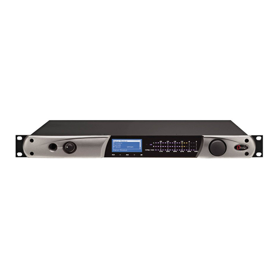
The Omnia.ONE User Interface Now that your Omnia.ONE is rack-mounted, connected to a program audio source, and turned on, you’re ready to learn how to operate it! This chapter covers the Front Panel User Interface, your window into the Omnia.ONE processor. -
Page 27: Audio I/O Level Display
AGC, Limiter and Clipper sections within the Omnia.ONE. (varies with style) If the “Menu Display” is currently showing on the Omnia.ONE’s LCD screen, press and hold the jog-wheel for two seconds to switch to the processing meter display as shown below. -
Page 28: Main Menu
The Omnia.ONE menu system has been designed to be intuitive and simple to use. Most operating parameters can be found under one of the menu headings and sub-headings, allowing adjustments to be made quickly and with ease. Rotating the jog-wheel sequentially highlights each menu item in turn. (See “Using the Jog... -
Page 29: Using The Jog Wheel
Using the Jog Wheel The main user control for the Omnia.ONE is the easy to use jog wheel with its integral push-switch. Using the control is both intuitive and efficient, making it easy to navigate the menu structure of the Omnia.ONE. Processing changes and system adjustments can be quickly made with ease without having to remember multiple controls, their positions, and what they do in each menu. -
Page 30: User Interface Tutorial - Input Source Selection And Peak Level Setting
(less headroom) is strongly discouraged unless there is another level-control device prior to the Omnia.ONE that will keep the input levels from reaching the maximum digital level of 0 dBFS. During normal operation, you should never see the red “0” segments light. -
Page 31: An Important Word About Time Delay
We have measured the propagation time delay, the amount of time it takes for the audio signal to travel from the analog input of Omnia.ONE to the output at approximately 7.7ms for the FM Style when using AES/EBU digital I/O, about 9.2ms when using analog I/O. This is enough for a slight voice-character coloration to be audible to the person speaking, but usually not enough to be a problem for talent monitoring off the air. -
Page 32: Chapter-3: Getting The Sound You Want
The Factory Presets If you go through and listen to all of the included factory presets, you should get a “feel” for them and find one to start with that is close to the sound you are looking for. -
Page 33: Increasing Density/Loudness
Conversely, if you have the luxury to strive for increased sound quality, we’ve got suggestions for you too! Omnia.ONE FM has been designed to minimize the trade-offs between quality and loudness, and we recommend that before starting the process of cranking it up, try to determine beforehand what sonic characteristics might be lacking. -
Page 34: Adding More Detail - When Loudness Isn't The Last Word
Once you have satisfactory results in one area (like overall density) you can then move the focus to the next area that you feel needs more tweaking. -
Page 35: Thunder Bass
Thunder Bass Omnia.ONE FM has the power to shake the walls with low end! If your source material has it, Omnia.ONE FM can expose that deep bass and do it with muscle! Tailoring Thunder Bass for more dominance is simple, and is done by adjusting the following parameters and in the order listed: 1. -
Page 36: The Factory Presets
95% may be a good idea, regardless of the presence of the “cliff effect” in your transmitter. The Factory Presets If you go through and listen to all of the included factory presets, you should get a “feel” for them and find one to start with that is close to the sound you are looking for. -
Page 37: Increasing Density/Loudness
The Omnia.ONE AM is definitely capable of generating moment-to-moment loudness; it has the muscle. It also maintains that famous Omnia clarity sought after by top programmers all over the world. Omnia.ONE AM is designed to minimize the impact of the quality vs. loudness trade-off. -
Page 38: Adding More Detail - When Loudness Isn't The Last Word
Once you have satisfactory results in one area (like overall density) you can then move the focus to the next area that you feel needs more tweaking. -
Page 39: Thunder Bass
Thunder Bass Omnia.ONE AM has the power to shake the walls with low end! If your source material has it, Omnia.ONE AM can expose that deep bass and do it with muscle! Tailoring Thunder Bass for more dominance is simple, and is done by adjusting the following parameters and in the order listed: 1. -
Page 40: Sensus Technology: Audio Processing
(or too expensive) to do in the past. Running on a platform of the latest high power DSP chips, the Omnia.ONE and our new Sensus technology takes digital dynamics processing into a completely new frontier. -
Page 41: So... What's So Smart About Sensus
In other words, what you hear at the output of the Omnia.ONE Multicast will bear no relationship to the audio quality that will be achieved after the audio has passed through the coding process! Need a corollary to this? It’s like trying to taste a pizza while still in the grocery store and staring at the raw ingredients that haven’t been purchased... -
Page 42: A Word About Density, Clarity, And Intelligibility
“breathing,” “dense,” or “mushy.” It can even induce exaggerated “swish/swirl” artifacts from the codec. Please remember that the core objective of the Omnia.ONE Multicast product is maximum intelligibility at low bitrates and processing that creates heavy density can completely mask that effort. A codec provisioning processor is in quite a different role than a conventional on-air processor. -
Page 43: Increasing Density/Loudness
Once you have satisfactory results in one area (like overall density) you can then move the focus to the next area that you feel needs more tweaking. -
Page 44: Equalization (Eq) Changes
Thunder Bass Omnia.ONE Multicast has the power to shake the walls with low end! If your source material has it, Omnia.ONE Multicast can expose that deep bass and do it with muscle! Tailoring Thunder Bass for more dominance is simple, and is done by adjusting the following parameters and in the order listed: 1. -
Page 45: Coded Audio Considerations
If everything is working properly the vocal quality should not change due to the coding process. If this is noticed, try reducing the Sensus function value by one adjustment click and then re-evaluate. -
Page 46: Equalization (Eq) Changes
The currently loaded preset is displayed to the right of Preset: on the top line of the Main Menu. You must select a factory preset to get started. Start by listening to each one with typical program material and then start with the one that sounded best to you. -
Page 47: Bass Enhancement
Bass Enhancement Omnia.ONE Studio Pro has the power to shake the walls with low end! If your source material has it, Omnia.ONE Studio Pro can expose that deep bass and do it with muscle! Tailoring the bass is simple, and is done by adjusting the following parameters and in the order listed: Increase the amount of Bass boost in the Enhance section. -
Page 48: Chapter-4: Main Menu Selections
100. FM Style Here is a block diagram of the fully digital, DSP based processing stages within the Omnia.ONE FM: The first processing stage is a Wideband AGC (Automatic Gain Control) for overall, automatic “hand on the pot” leveling to keep the following multi-Band stages in their “sweet spot”, followed by the Bass Enhancers (Deep Bass EQ and Phat Bass) and the Crossover (XO), which splits the audio into 4 bands for optimum processing in each of the Bass (L), Midrange (M), Presence (P) and Treble (H) frequency ranges. -
Page 49: Preset
Preset Omnia.ONE is equipped with a selection of factory presets that can be used to instantly configure the processing for common applications. The currently loaded preset is displayed to the right of Preset: on the top line of the Main Menu. -
Page 50: Save Preset
" ^ " symbol and click again. The new character appears. Now rotate the knob to select the desired character for it and click to accept. (Note that this inserts a new character before the one selected, and keeps the originally selected character intact as what it was before choosing "^") -
Page 51: Rename Preset
<-Exit Click on this option to return to the Main Menu. Adjust Processing This submenu allows changes to be made in any of the Omnia.ONE’s several dozen processing parameters. These adjustments alter the sound and texture of the audio. <-Exit Click on this option to return to the Processing menu. - Page 52 AGC Drv (AGC Drive) This control adjusts the amount of drive to the wideband AGC stage. Increasing the drive causes deeper compression to be achieved, and deeper compression allows quieter passages in the input audio to be raised further than if lesser drive (and less compression) was used.
- Page 53 reduction in the lower AGC bands and may cause muddiness with certain program material. A little goes a long way. Warmth This Warm Bass EQ is a shelf boost at 150 Hz. Warmth EQ compensates for program material that is naturally lacking in upper-bass fullness. Be judicious about applying too much, as the resonant frequency of many automobile interiors lies in this frequency range! Also, too much can cause excessive gain reduction in the following 4-Band AGC stage.
-
Page 54: Low Band Agc
OV Lim Drv (Overall Limiter Drive) Adjusts the overall amount of drive to all four bands of the multiband Limiter section simultaneously over a + / - 6 dB range. Higher settings will increase density. This can increase loudness but be careful because too much gain reduction in the limiters can lead to a “wall of sound”... -
Page 55: High Band Agc
Pres Band AGC (Presence Band AGC) See description of settings for Low Band AGC High Band AGC See description of settings for Low Band AGC Low Band Limiter LFLim Drv (Low Frequency Limiter Drive) Adjusts the drive level to the individual Limiter band. Used when you desire more or less density in a specific band. -
Page 56: Mid Band Limiter
In fact, instead of reducing the output of one of the audio bands in the Final Mixer section, you could instead “dynamically reduce” the level in that band (which also increases density in that band) by lowering the limiter threshold. - Page 57 amount of perceived bass in the program material. Be careful! Too much clipping by the Bass Clipper can soften bass 'punch'. It may also be heard as a “rattling” sound in the bass. Girth Clip When “ON”, this Bass Clipper style is designed to create a phatter effect to low frequencies, and it will help create the illusion of more bass on smaller speakers.
- Page 58 Click on this option to return to the Adjust Processing submenu. Clipper The Clipper is the Omnia.ONE’s final limiting stage. Here is where the Omnia.ONE’s loudness versus quality advantage is most evident! The main clipper is a very powerful algorithm, is highly over-sampled, and is fully anti-aliased.
-
Page 59: Input/Output
Failover Time is a feature that when set to a value other than zero (disabled) allows the Omnia.ONE to automatically select another input source if the currently selected one fails. Failover Time is the amount of time that will elapse after the failure of audio on the primary input source before the unit makes the decision to switch to the secondary (failover) input source. - Page 60 “Both” is typically selected if it sounds “better” to an announcer (monitoring themselves in headphones using the output of the processing) than “None”. One of the two settings should. The goal is to make the relative phase of the headphone feed more in phase with the announcer’s own bone conduction.
- Page 61 Allows a +/-3dB adjustment of the right analog audio channel gain to correct minor problems in equipment following the Omnia.ONE. The left channel output gain is not affected by this control and is set using the master Analog Level control previously described.
- Page 62 Note: Normally, the “Off” selection under the Pre-emphasis options would not be used in conventional FM transmission applications, but is provided in instances where processing of a flat signal is desired. One example would be when preprocessing prior to a satellite uplink in distributed radio networks.
- Page 63 (STL). In these kinds of installations it is very important that the Omnia.ONE FM is the ONLY device applying the pre-emphasis. All other equipment following the Omnia.ONE FM must have their pre-emphasis disabled for optimum peak modulation control and sound quality.
- Page 64 Stereo Generator SCA Input Gain (Control On Rear Panel) The SCA Input Gain control is an analog trimpot and does not appear in the menu. This trimpot is located just above the SCA Input BNC jack on the rear panel. A small flat-blade screwdriver will be needed to adjust it.
- Page 65 Use this to save your I/O configuration as the system default or save more than one configuration if the unit will be used with different external equipment configurations. These saved configurations can be recalled using the “Load IO Config”...
-
Page 66: Administrative
Now rotate the knob to select the desired character for it and click to accept. (Note that this inserts a new character before the one selected, and keeps the originally selected character intact as what it was before choosing "^") When you are finished, simply rotate the knob clockwise with the cursor in “select”... -
Page 67: Network Configuration
Accepts data in the form of four octets to describe the Ipv4 network address assigned to the Omnia.ONE’s network interface. The entries have the form of: [ octet] . [ octet] . [ octet ] . [ octet] which when entered may appear as a network address such as: 192 . -
Page 68: Lock Front Panel
Rotating it counter-clockwise will scroll through the numeric characters first, and then through the lower case English alphabet. Once the desired character is found, click to accept that character, rotate the jog wheel one notch clockwise to advance the cursor to the next position and click again to display the editing cursor. -
Page 69: Sg Style
SG Style The Omnia ONE SG style is designed to accept the output of an external FM audio processor either directly or through a linear digital STL system. It has no audio processing onboard except for a composite clipper stage designed to remove small overshoots from the processed input audio if needed. - Page 70 [SB Mode] (Sideband Mode - DSB or SSB) The normal setting for the stereo generator is the DSB setting which provides the full double- sideband, suppressed carrier L-R signal. The special SSB setting provides a single-sideband, suppressed carrier L-R signal that can help reduce multipath and provide increased protection to the baseband spectrum.
-
Page 71: Discrete I/O
When set to a value other than zero (disabled) allows the Omnia.ONE to automatically select another input source if the currently selected one fails. Failover Time is the amount of time that will elapse after the failure of audio on the primary input source before the unit makes the decision to switch to the secondary (failover) input source. - Page 72 Adjusts the level of the right channel input only over a range of +/- 3.0dB in 0.1dB steps. Invert Inverts the phase of one channel (L inverts only the left channel) (R inverts only the right channel) or BOTH channels. None (the default) passes through both channels normally.
- Page 73 [Mono L+R] - Configures the DSP processing chain to have both the Left and Right internal channels fed from the sum of the Left Channel and Right Channels of the input source selected. Note that this selection is active in all sources selected as Primary and Secondary (Failover) audio sources.
- Page 74 Use this to save your I/O configuration as the system default or save more than one configuration if the unit will be used with different external equipment configurations. These saved configurations can be recalled using the “Load IO Config” option. To save an IO configuration proceed as follows: Highlight “Save IO Config”...
-
Page 75: Load Io Config
(Note that this inserts a new character before the one selected, and keeps the originally selected character intact as what it was before choosing "^") When you are finished, simply rotate the knob clockwise with the cursor in “select” mode until the Save button is highlighted and click to save the configuration preset. -
Page 76: Administrative
Administrative About Presents a dialog displaying the Omnia.ONE software style, firmware release version and front panel software version currently active in the unit. Contrast Adjusts the contrast of the front panel LCD display to optimize it for various viewing angles. -
Page 77: Lock Front Panel
English alphabet. Once the desired character is found, click to accept that character, rotate the jog wheel one notch clockwise to advance the cursor to the next position and click again to display the editing cursor. -
Page 78: Am Style
AM Style Here is a block diagram of the fully digital, DSP-based processing stages within the Omnia.ONE AM: The first processing stage is a Wideband AGC (Automatic Gain Control) for overall, automatic “hand on the pot” leveling to keep the following 4-Band stages in their “sweet spot”, followed by the Bass Enhancers (Deep Bass EQ and Phat Bass) and the Crossover (XO), which splits the audio into 4 bands for optimum processing in each of the Bass (L), Midrange (M), Presence (P) and Treble (H) frequency ranges. -
Page 79: Preset
Preset Omnia.ONE is equipped with a selection of factory presets that can be used to instantly configure the processing for common applications. The currently loaded preset is displayed to the right of Preset: on the top line of the Main Menu. -
Page 80: Delete Preset
" ^ " symbol and click again. The new character appears. Now rotate the knob to select the desired character for it and click to accept. (Note that this inserts a new character before the one selected, and keeps the originally selected character intact as what it was before choosing "^") -
Page 81: Exit
<-Exit Click on this option to return to the Main Menu. Adjust Processing This submenu allows changes to be made in any of the Omnia.ONE’s several dozen processing parameters. These adjustments alter the sound and texture of the audio. <-Exit Click on this option to return to the Main Menu. - Page 82 AGC Att (AGC Attack) The attack control adjusts how fast the AGC responds to sudden increases in audio level, and higher numbers equate to faster response times. Faster attack times reduce the transient nature of the input audio, while slower attack times improve it. Extremely slow attack times must be used with caution because allowances must be made in later stages to not overload them during the time when the broadband AGC is adjusting the level downwards.
- Page 83 is unable to reproduce. On systems with larger speakers, the effect of Phat Bass becomes subtler because the extended frequency response of those systems allows the fundamentals of the low notes to be heard, masking the added harmonics contributed by Phat Bass.
- Page 84 Pres Drive Adjusts the amount of gain reduction in the Presence Band AGC. Higher numbers result in more drive and because of the increased compression, a more consistent output from the band. Hi Drive Adjusts the amount of gain reduction in the High Band AGC. Higher numbers result in more drive and because of the increased compression, a more consistent output from the band.
- Page 85 Gt Thresh (Gate Threshold) When the input audio falls below a certain level, the gain control action of the AGC stage is “frozen” by the gate. The level at which this freeze, or hold takes place is controlled by the setting of the Gate Threshold control. Higher numbers cause the gate to activate at higher audio levels.
- Page 86 In fact, instead of reducing the output of one of the audio bands in the Final Mixer section, you could instead “dynamically reduce” the level in that band (which also increases density in that band) by lowering the limiter threshold.
- Page 87 Mid Band Limiter See description of settings for Low Band Limiter Presence Band Limiter See description of settings for Low Band Limiter High Band Limiter See description of settings for Low Band Limiter Bass Clipper The Bass Clipper operates between the output of the Low Band Limiter and the Low Band Mixer, the output of which feeds the main Clipper.
- Page 88 Click on this option to return to the Adjust Processing submenu. Clipper The Clipper is the Omnia.ONE’s final limiting stage. Here is where the Omnia.ONE’s loudness versus quality advantage is most evident! The main clipper is a very powerful algorithm, is highly over-sampled, and is fully anti-aliased.
-
Page 89: Input/Output
<-Exit Click on this option to return to the Input/Output menu. Input Src (Input Source) Allows the selection of Analog, AES/EBU (digital) or Livewire as the primary input source to the Omnia.ONE. Fover Time (Failover Time) - Page 90 No Channel inversion is performed (factory default) [Both] – Both left and right channel phase is inverted. “Both” is typically selected if it sounds “better” to an announcer (monitoring themselves in headphones using the output of the processing) than “None”. One of the two settings...
- Page 91 XLR male connectors. This control adjusts both the left d right stereo channels simultaneously. Right Trim Allows a +/-3dB adjustment of the right analog audio channel gain to correct minor problems in equipment following the Omnia.ONE. The left channel output gain is not...
- Page 92 Allows a +/-3dB adjustment of the right digital audio channel gain to correct minor left/right balance problems in equipment following the Omnia.ONE. The left channel output gain is not affected by this control and is set using the master AES Level control previously described.
- Page 93 The following spectrograph displays the performance of the 10kHz NRSC-compliant low pass filter: [Tilt EQ] (Tilt Equalization) [Tilt Freq] (Tilt Frequency) Low frequency tilt and equalization controls have been provided after the Omnia.ONE AM’s clipper section in order to compensate for certain design deficiencies in older...
- Page 94 Omnia’s Tilt Equalizer when it is being used on older, less adequate transmitters! Navigate to the Omnia.ONE’s Output Menu, and reduce the output levels to 0dBU on both Left and Right channels. Connect a sine wave Audio Oscillator to the Omnia.ONE AM audio inputs. Set the oscillator to provide a 50 Hz, 0dBu output.
- Page 95 After optimizing the Tilt controls for your particular transmitter, the Tilt adjustment is complete. Normal programming may be applied and the Omnia.ONE’s output levels adjusted for the desired negative and positive modulation. Please see the following oscilloscope photographs of three examples of tilt equalization on the next page.
- Page 96 Use this to save your I/O configuration as the system default or save more than one configuration if the unit will be used with different external equipment configurations. These saved configurations can be recalled using the “Load IO Config” option. To save an IO configuration proceed as follows: Highlight “Save IO Config”...
-
Page 97: Administrative
(Note that this inserts a new character before the one selected, and keeps the originally selected character intact as what it was before choosing "^") When you are finished, simply rotate the knob clockwise with the cursor in “select” mode until the Save button is highlighted and click to save the configuration preset. - Page 98 Accepts data in the form of four octets to describe the Ipv4 network address assigned to the Omnia.ONE’s network interface. The entries have the form of: [ octet] . [ octet] . [ octet ] . [ octet] which when entered may appear as a network address such as: 192 .
-
Page 99: Lock Front Panel
English alphabet. Once the desired character is found, click to accept that character, rotate the jog wheel one notch clockwise to advance the cursor to the next position and click again to display the editing cursor. -
Page 100: Multicast/Dab Style
Omnia.ONE: 24, 32, 48 and 64 kbps. By starting with one of the factory presets (usually the one named closest to the primary programming and bitrate to be used on the channel the Omnia.ONE Multicast is processing) and then altering it using the controls in the Processing menu, you may change the sound of a preset and then save it with your changes as a user preset for either immediate use or later recall. -
Page 101: Preset
Preset Omnia.ONE is equipped with a selection of factory presets that can be used to instantly configure the processing for common applications. The currently loaded preset is displayed to the right of Preset: on the top line of the Main Menu. -
Page 102: Delete Preset
" ^ " symbol and click again. The new character appears. Now rotate the knob to select the desired character for it and click to accept. (Note that this inserts a new character before the one selected, and keeps the originally selected character intact as what it was before choosing "^") -
Page 103: Adjust Processing
Adjust Processing This submenu allows changes to be made in any of the Omnia.ONE’s several dozen processing parameters. These adjustments alter the sound and texture of the audio. <-Exit Click on this option to return to the Processing menu. Pre-processing... - Page 104 The release control adjusts how fast the AGC recovers from periods of more gain reduction when the input audio levels fall. Faster release times (higher numbers) result in a more dense sound. Even though the Omnia uses program controlled release algorithms, setting the control for extremely fast release times can result in ‘pumping’.
- Page 105 Xover (Crossover) The crossover splits the audio signal into 4 independent bands to enable optimum processing for the bass (L), midrange (M), presence (P) and treble (H) frequency ranges. There are two four-band processing stages that share the same crossover. The crossover points are 180Hz, 1kHz and 3.3kHz plus 6.5kHz for the optional 5 limiter band.
- Page 106 Low Band AGC Attack The attack control adjusts how fast the AGC responds to sudden increases in audio level, and higher numbers equate to faster response times. Faster attack times reduce the transient nature of the input audio, while slower attack times improve it. Extremely slow attack times must be used with caution so as not to allow later stages to be overloaded during the time when the AGC is adjusting the level downwards.
- Page 107 Low Band Limiter LFLim Drv (Low Frequency Limiter Drive) Adjusts the drive level to the individual Limiter band. Used when you desire more or less density in a specific band. These Limiter Drive controls can also be used as secondary dynamic EQ controls after the Drive controls in the AGC Xover.
- Page 108 The drawback is that it can generate intermodulation distortion in the Final Limiter and increase artifacts in the codec employed after the Omnia.ONE Multicast. When both the Girth Clip and Tight Clip settings are both set to “OFF”, the Bass Clipper is effectively bypassed.
- Page 109 Mid Band Adjusts the output level of the mid band limiter into the following Final Limiter stage. Higher numbers result in more midrange but too much mix level can make the following final limiter work unnecessarily hard. Presence Band Adjusts the output level of the presence band limiter into the following Final Limiter stage. Higher numbers result in more presence but too much mix level can make the following final limiter work unnecessarily hard.
- Page 110 Omnia.ONE Multicast offers this feature as a low pass output filter that can be set to one of seven stop band frequencies. Each of the filters possess minimal passband ripple and are phase linear below cutoff.
-
Page 111: Input/Output
The Nyquist Theorem states that the maximum frequency that may be applied to a sampled data system is one half the sampling frequency. When signals beyond half the sampling frequency are present, aliasing occurs which causes the appearance of an inverted spectral image of the audio spectrum to be “folded around” the... - Page 112 Failover Time is a feature that when set to a value other than zero (disabled) allows the Omnia.ONE to automatically select another input source if the currently selected one fails. Failover Time is the amount of time that will elapse after the failure of audio on the primary input source before the unit makes the decision to switch to the secondary (failover) input source.
- Page 113 “Both” is typically selected if it sounds “better” to an announcer (monitoring themselves in headphones using the output of the processing) than “None”. One of the two settings should. The goal is to make the relative phase of the headphone feed more in phase with the announcer’s own bone conduction.
- Page 114 Allows a +/-3dB adjustment of the right analog audio channel gain to correct minor problems in equipment following the Omnia.ONE. The left channel output gain is not affected by this control and is set using the master Analog Level control previously described.
- Page 115 Use this to save your I/O configuration as the system default or save more than one configuration if the unit will be used with different external equipment configurations. These saved configurations can be recalled using the “Load IO Config” option. To save an IO configuration proceed as follows: Highlight “Save IO Config”...
-
Page 116: Administrative
(Note that this inserts a new character before the one selected, and keeps the originally selected character intact as what it was before choosing "^") When you are finished, simply rotate the knob clockwise with the cursor in “select” mode until the Save button is highlighted and click to save the configuration preset. - Page 117 Accepts data in the form of four octets to describe the Ipv4 network address assigned to the Omnia.ONE’s network interface. The entries have the form of: [ octet] . [ octet] . [ octet ] . [ octet] which when entered may appear as a network address such as: 192 .
-
Page 118: Lock Front Panel
English alphabet. Once the desired character is found, click to accept that character, rotate the jog wheel one notch clockwise to advance the cursor to the next position and click again to display the editing cursor. -
Page 119: Studio Pro Style
Preset Omnia.ONE is equipped with a selection of factory presets that can be used to instantly configure the processing for common applications. The currently loaded preset is displayed to the right of Preset: on the top line of the Main Menu. -
Page 120: Adjust Processing
We will discuss the Save Preset, Delete Preset, Rename Preset and <-Exit options first before delving into the details of the Adjust Processing menu. Adjust Processing This submenu allows changes to be made in any of the Omnia.ONE’s several dozen processing parameters. These adjustments alter the sound and texture of the audio. <-Exit Click on this option to return to the Processing menu. - Page 121 AGC Att (AGC Attack) The attack control adjusts how fast the AGC responds to sudden increases in audio level, and higher numbers equate to faster response times. Faster attack times reduce the transient nature of the input audio, while slower attack times improve it. Extremely slow attack times must be used with caution because allowances must be made in later stages to not overload them during the time when the broadband AGC is adjusting the level downwards.
- Page 122 with larger speakers, the effect of Phat Bass becomes subtler because the extended frequency response of those systems allows the fundamentals of the low notes to be heard, masking the added harmonics contributed by Phat Bass. Be careful though, too much Phat Bass boost can lead to excessive gain reduction in the lower AGC bands and may cause muddiness with certain program material.
- Page 123 consistent. Be careful though because too much compression can cause the program material to sound less natural and cause low-level noise in the program material to be brought up. OV Lim Drv (Overall Limiter Drive Adjusts the overall amount of drive to all four bands of the multiband Limiter section simultaneously over a + / - 6 dB range.
- Page 124 <-Exit Click on this option to return to the Adjust Processing submenu. Mid Band AGC See description of settings for Low Band AGC Pres Band AGC (Presence Band AGC) See description of settings for Low Band AGC High Band AGC See description of settings for Low Band AGC Low Band Limiter LFLim Drv (Low Frequency Limiter Drive)
- Page 125 Be careful! Too much clipping by the Bass Clipper can soften bass 'punch'. It may also be heard as a “rattling” sound in the bass or cause additional artifacts in the codec following the Omnia.ONE Studio Pro. Girth Clip When “ON”, this Bass Clipper style is designed to create a phatter effect to low frequencies, and it...
- Page 126 Click on this option to return to the Adjust Processing submenu. Final Limit The Omnia.ONE Studio Pro employs a defeatable final look-ahead limiter to provide absolute precision peak control. This limiter has been designed to minimize processing side-effects like IM distortion, which are usually associated with limiters of this type.
-
Page 127: Input/Output
Final Limiter. Ensure that there is enough headroom in the equipment following the Omnia.ONE or reduce the Omnia.ONE’s output level as needed to prevent clipping of the output or overloading the input of the equipment following the Omnia.ONE. - Page 128 Failover Time is a feature that when set to a value other than zero (disabled) allows the Omnia.ONE to automatically select another input source if the currently selected one fails. Failover Time is the amount of time that will elapse after the failure of audio on the primary input source before the unit makes the decision to switch to the secondary (failover) input source.
- Page 129 “Both” is typically selected if it sounds “better” to an announcer (monitoring themselves in headphones using the output of the processing) than “None”. One of the two settings should. The goal is to make the relative phase of the headphone feed more in phase with the announcer’s own bone conduction.
- Page 130 Allows a +/-3dB adjustment of the right analog audio channel gain to correct minor problems in equipment following the Omnia.ONE. The left channel output gain is not affected by this control and is set using the master Analog Level control previously described.
-
Page 131: Save Io Config
" ^ " symbol and click again. The new character appears. Now rotate the knob to select the desired character for it and click to accept. (Note that this inserts a new character before the one selected, and keeps the originally selected character intact as what it was before choosing "^") -
Page 132: Administrative
Click on this option to return to the Main Menu. Administrative About Presents a dialog displaying the Omnia.ONE software style, firmware release version and front panel software version currently active in the unit. Contrast Adjusts the contrast of the front panel LCD display to optimize it for various viewing angles. - Page 133 Accepts data in the form of four octets to describe the Ipv4 gateway address assigned to the Omnia.ONE’s network interface. The entries have the form of: [ octet] . [ octet] . [ octet ] . [ octet] which when entered may appear as a network address such as: 192 .
-
Page 134: Lock Front Panel
English alphabet. Once the desired character is found, click to accept that character, rotate the jog wheel one notch clockwise to advance the cursor to the next position and click again to display the editing cursor. -
Page 136: Appendix A: Performance Specifications
Appendix A: Performance Specifications Omnia.ONE FM Note: Discrete I/O measurements have been made in "Bypass" mode (available in the Input/Output menu). FM composite measurements have been made using the "Proof_Perf" preset. General Audio Specifications Frequency Response: Complies with the standard 50 or 75 microsecond pre-emphasis curve within ± 0.50 dB, 30 Hz to 15 kHz. - Page 137 Electronically balanced. Input impedance 10k ohms resistive. Maximum Input Level: +22 dBu. Nominal Input Level: +4dBu, which nets a -18dBFS input meter reading on a steady- state signal when the Input Gain control is set to 0.0dB. Program material with a nominal average level (VU reading) of +4dBu will typically produce peak readings on the input meter in the range of -12 dBFS to -6dBFS.
- Page 138 Humidity: 0-95% RH, non-condensing. Dimensions: 19" wide x 1.75" high x 16" deep (48.26cm wide x 13.335 cm high x 40.64 cm deep) including connectors. Unit requires one EIA rack space for mounting. Shipping Weight: 12 lbs. / 5.5 kg StudioHub...
-
Page 139: Omnia.one Sg
Omnia.ONE SG General Audio Specifications Frequency Response: Complies with the standard 50 or 75 microsecond pre-emphasis curve within ± 0.50 dB, 30 Hz to 15 kHz. The analog left/right outputs and AES/EBU Digital outputs can be configured for flat or pre- emphasized output. - Page 140 A/D Conversion: Crystal Semiconductor CS5361, 24 bit 128x over-sampled delta sigma converter with linear-phase anti-aliasing filter. Pre-ADC anti-alias filter, with high-pass filter at <10 Hz. Connectors: Two, EMI-suppressed XLR-female. Pin 1 chassis ground, Pin 2 "Hot". Analog Audio Output: Left/Right Stereo. Electronically balanced. Output Impedance 20 ohms.
- Page 141 Humidity: 0-95% RH, non-condensing. Dimensions: 19" wide x 1.75" high x 16" deep (48.26cm wide x 13.335 cm high x 40.64 cm deep) including connectors. Unit requires one EIA rack space for mounting. Shipping Weight: 12 lbs. / 5.5 kg StudioHub...
-
Page 142: Omnia.one Am
Omnia.ONE AM Note: Discrete I/O measurements have been made in "Bypass" mode (available in the Input/Output menu). Note: All measurements made with the supplied “FACT_TEST” preset, which is available in the Preset Submenu. System Frequency Response Complies with the NRSC emphasis curve within ± 0.50 dB, 30 Hz to 10 kHz. - Page 143 Operating Temperature: 32 to 122 deg. F / 0 to 50 deg. C for all operating voltage ranges. Humidity: 0-95% RH, non-condensing. Dimensions: 19" wide x 1.75" high x 16" deep (48.26cm wide x 13.335 cm high x 40.64 cm deep) including connectors. Unit requires one EIA rack space for mounting.
- Page 144 Shipping Weight: 12 lbs. / 5.5 kg StudioHub is a registered trademark of Radio Systems. Telos/Omnia Research and Development is constantly working to improve the quality of our products. Actual specifications are subject to change or improvement without notice.
-
Page 145: Omnia.one Multicast/Dab & Studio Pro
Omnia.ONE Multicast/DAB & Studio Pro As of February 2009 – Version 2.2 Multicast, DAB or Studio Pro Software Note: All measurements made using "Bypass" mode, which is available in the Input/Output menu. General Audio Specifications Frequency Response: ± 0.50 dB, 20 Hz to 20 kHz with high pass filter disabled. - Page 146 Humidity: 0-95% RH, non-condensing. Dimensions: 19" wide x 1.75" high x 16" deep (48.26cm wide x 13.335 cm high x 40.64 cm deep) including connectors. Unit requires one EIA rack space for mounting. Shipping Weight: 12 lbs. / 5.5 kg StudioHub...
-
Page 148: Appendix B: Troubleshooting/Service/Warranty
RS-232 port, as well as viewing of any error messages that may be encountered. This chapter explains the various boot up and error messages that may be encountered while troubleshooting the unit. We'll cover some basic troubleshooting techniques for isolating possible Omnia.ONE problems in the field, and also how to obtain help or repair service from Omnia. -
Page 149: Diagnostics And Error Messages
Diagnostics and Error Messages To run a system diagnostics check of the Omnia.ONE unit that can be used by Telos/Omnia Customer Support personnel in case of difficulty with the unit, click on the “Factory Diagnostics” link option in the Utilities section at the bottom of the Configuration screen: A report similar to the below will be generated. -
Page 150: Electrical And Mechanical Safety Note
If the signal is dead at all three, then this points to a digital audio problem after the dynamic processing DSP chips. If one of the output sections is not operating, then it can be localized to that specific section. -
Page 151: Obtaining Service
Obtaining Service • Before contacting Omnia Customer Support, please have the serial number of the unit (located on a barcode sticker on the rear panel in this format: 0220WXXXX) and a description of the symptoms/problems ready for the technician. • All units being returned to for service MUST have a Return Authorization (RA) number assigned to them first. -
Page 152: Warranty
Warranty This Warranty covers "the Products," which are defined as the various audio equipment, parts, software and accessories manufactured, sold and/or distributed by TLS Corp., d/b/a Omnia (hereinafter "Omnia"). With the exception of software-only items, the Products are warranted to be free from defects in material and workmanship for a period of two years from the date of receipt by the end-user. -
Page 154: Appendix C: Remote Control And Software Update Procedure
The above screenshot shows the Processing screen of the Omnia.ONE’s built-in remote control applet. NOTE: The FM software style will be used to illustrate the Omnia.ONE Remote Control screens in this chapter. Some screens and their available controls will differ slightly in the other styles. -
Page 155: Remote
Once Java is installed on your computer, using a Web browser, connect to the IP address of your Omnia.ONE as follows: (see Network Configuration on Page 48 if you need to enter the Network parameters into the Omnia.ONE) Open a standard Web Browser on your computer and connect to the Omnia.ONE by entering:... -
Page 156: Preset Tab
Omnia.ONE’s front panel. To refresh the front panel preset name, simply click the Omnia.ONE’s jog wheel to enter one of the menus and then click “<-Exit”. (Or enter the Preset menu, rotate the Jog Wheel to the right and select “Cancel*”... -
Page 157: In Tab
To change the “radio button” settings, simply click once on the button or name of the desired setting and release. In Tab Clicking on the “In” tab will display all of the controls for the Omnia.ONE’s Input menu in the main applet screen. Adjustment of the controls works the same way as described above... -
Page 158: Out Tab
To enter the IO Configuration menu, click on the “IO” tab. Here you can select a previously saved IO Configuration from the Omnia.ONE’s memory, save your changes to an existing IO configuration, save your IO settings as a new IO Configuration or delete an existing IO Configuration. -
Page 159: Livewire
Livewire output stream mode is selected. The Livewire output can also be disabled here. In the “Input to Omnia.ONE” section, the channel from your Livewire system to be input to the Omnia.ONE is selected. The Mode: dropdown box should normally be left at the default setting: “From source”. -
Page 160: File Transfer
Presets are saved as small, text-based files with the “.opr” extension. To upload a previously saved user preset to the Omnia.ONE, use the file entry box (or the browse button) to enter the path to the preset file name to be uploaded and press the “Upload” button. -
Page 161: I/O Configuration File Transfer
So, after uploading a preset to the unit from the remote, simply save any preset as a new name, rename a preset or delete a preset using the front panel jog wheel and the uploaded preset should then show up in the front panel’s preset list. -
Page 162: Software Update Procedure
This is a safeguard against loss of power or other interruption during the update. In this event, the Omnia.ONE should still boot into the active bank containing the “old” software (but it is best to avoid interruptions in any case). - Page 163 1, double-click it so that it appears in the “Update File:” box, then click the “Update” button. The file will now be uploaded to the Omnia.ONE. This may take up to 5 minutes. A progress bar may or may not appear, depending on the browser being used but once the file is successfully uploaded to the Omnia.ONE, the following “Update Initiated”...
- Page 164 Scroll down the Configuration page to find the “Select Software Bank:” section: In this example, the new software has been uploaded to Bank 1. You will notice that the previous software (Bank 0 in this case) is still selected and running. You can choose to change to the other bank to activate the new software or keep running the current software and reboot later.
-
Page 166: Appendix D: Gpi Using The "Interface" Connector (New In Version 2.6)
Appendix D: GPI using the “INTERFACE” connector (New in Version 2.6) Pin 1: +5VDC Out Pin 2: In COM+ Pin 3: IN 1: Trigger input #1 Pin 4: IN 2: Trigger input #2 Pin 5: IN 3: Trigger input #3 Pin 6: IN 4: Trigger input #4 Pins 7,8,9: GND For operation, a voltage must be applied to voltage input on pin 2. - Page 167 The Omnia ONE offers the ability to control several functions by means of trigger events (a trigger event is either a physical contact closure or a virtual LiveWire GPIO event). Currently, presets may be selected, the primary and secondary input sources may be selected, and the failover state may be set (forcing a switch to the secondary input) or cleared (forcing a restore to primary input).
- Page 168 Each of the five pins acts independently of the others. Each pin can have one preset assigned to a rising edge on the pin and one preset assigned to a falling edge (or "no action" may be selected for either or both edges).
- Page 169 GPO 3: -- PRI <src> -- Select the given source, <src>, as the primary input source. <src> must be one of: ANA (for analog), AES (for AES/EBU), or LWR (for LiveWire). -- SEC <src> -- Select the given source, <src>, as the secondary input source that will be used in case of failover.
Need help?
Do you have a question about the ONE and is the answer not in the manual?
Questions and answers