Turbo Air TGM-69R Service Manual
Commercial refrigerator & freezer
Hide thumbs
Also See for TGM-69R:
- Installation and operation manual (8 pages) ,
- Service manual (128 pages) ,
- Service manual (85 pages)

Related Manuals for Turbo Air TGM-69R


Summary of Contents for Turbo Air TGM-69R
- Page 1 Headquarter: 1250 Victoria street CARSON, CA 90746 & Canada Toll Free 800-627-0032 TEL: (562)981-0123 FAX: (562)981-0124 www.turboairinc.com 0210001...
- Page 2 Commercial Refrigerator & Freezer Service Manual Model No.: TGM-69R TGM-48R TGM-45R TGM-35R TGM-33R TGM-22R TGM-14R TGM-11R TGM-5R TGF-23F TGF-13F TGF-9F...
- Page 3 Commercial Refrigerator Service Manual Model No.: TGM-69R TGM-48R TGM-45R TGM-35R TGM-33R TGM-22R TGM-14R TGM-11R TGM-5R...
-
Page 4: Table Of Contents
TABLE OF CONTENTS <REFRIGERATOR> 1. FEATURE CHART ......................2 2. WIRING DIAGRAM ......................9 3. REFRIGERANT CYCLE DIAGRAM ................13 4. SPECIFICATION OF MAIN COMPONENTS ............... 14 5. TROUBLE SHOOTING CHART ..................17 1. REFRIGERATION SYSTEM ........................17 2. REFRIGERATION SYSTEM ........................18 3. -
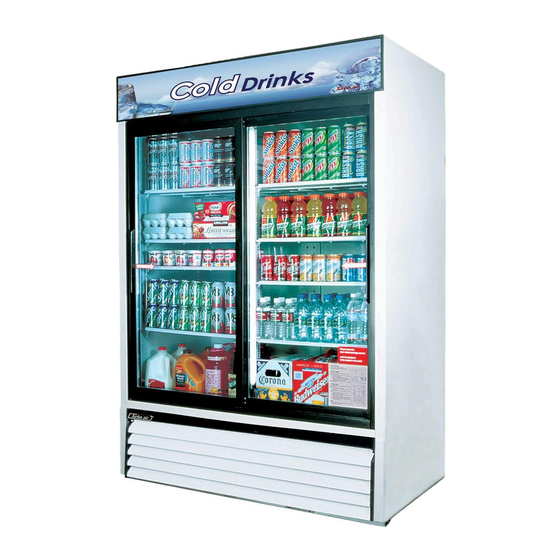
Page 5: Feature Chart
1. FEATURE CHART SIGN PANEL • Model : TGM-69R DOOR HANDLE GLASS DOOR BOTTOM GRILL LEVELING LEG < FRONT > EVAPORATOR FAN BLADE LAMP SWITCH EVAPORATOR FAN MOTOR EVAPORATOR COIL LAMP KNOB EVAPORATOR DRAIN PAN SHELF CONDENSER COIL DRAIN PAN COMPRESSOR <... - Page 6 FEATURE CHART • Model : TGM-48R, 45R, 35R, 33R SIGN PANEL DOOR DOOR HANDLE BOTTOM GRILL LEVELING LEG < FRONT > EVAPORATOR EVAPORATOR COIL • Model : TGM-48R, 35R FLOURESCENT EVAPORATOR FAN MOTOR LAMP EVAORATOR FAN BLADE THERMOSTAT FLOURESCENT LAMP SHELF CONDENSER FAN BLADE CONDENSER...
- Page 7 FEATURE CHART • Model : TGM-45R, 33R EVAPORATOR COIL COMPRESSOR CONDENSER COIL DRAIN PAN < SIDE > • Model : TGM-22R SIGN PANEL SHELF BOTTOM GRILL DOOR GLASS LEVELING < FRONT >...
- Page 8 FEATURE CHART EVAPORATOR EVAPORATOR FAN MOTOR EVAPORATOR COIL THERMOSTAT FAN BLADE • Model : TGM-22R BALLAST SIGN PANEL FLUORES -CENT LAMP DRAIN ELBOW DOOR HINGE DRAIN HOSE SUCTION PIPE -COVER HANDLE DOOR HINGE BOTTOM COMPRESSOR CONDENSER DRAIN PAN COIL CONDENSER FAN BLADE CONDENSER FAN MOTOR <...
- Page 9 FEATURE CHART EVAPORATOR COIL EVAPORATOR FAN MOTOR • Model : TGM-14R BALLAST SIGN PANEL FLUORES -CENT LAMP DOOR HANDLE DRAIN PAN CONDENSER COIL COMPRESSOR CONDENSER FAN MOTOR < SIDE > • Model : TGM-11R FLUORESCENT SIGN PANEL LAMP STICKER SHELF BOTTOM GRILL LEVELING LEG <...
- Page 10 FEATURE CHART EVAPORAOR FAN MOTOR • Model : TGM-11R EVAPORATOR FAN BLADE EVAPORATOR COIL CONDENSER FAN MOTOR CONDENSER FAN BLADE COMPRESSOR CONDENSER COIL DRAIN PAN < SIDE > • Model : TGM-5R THERMOSTAT CONTROL BOX FLUORE SCENT LAMP EVAPORATOR SHELF DRAIN PAN GASKET DOOR...
- Page 11 FEATURE CHART • Model : TGM-5R DOOR HANDLE CONDENSER LEVELING LEG < SIDE >...
-
Page 12: Wiring Diagram
2. WIRING DIAGRAM • Model : TGM-69R • Model : TGM-48R... - Page 13 WIRING DIAGRAM • Model : TGM-45R • Model : TGM-35R...
- Page 14 WIRING DIAGRAM • Model : TGM-33R • Model : TGM-22R...
- Page 15 WIRING DIAGRAM • Model : TGM-14R • Model : TGM-11R (13W) F/M1 F/M2 COMPRESSOR & P-RELAY POWER PLUG • Model : TGM-5R...
-
Page 16: Refrigerant Cycle Diagram
3. REFRIGERANT CYCLE DIAGRAM • All the models choose R-134a as a refrigerant. R-134a is CFC-Free. -
Page 17: Specification Of Main Components
4. SPECIFICATION OF MAIN COMPONENTS 1. COMPRESSOR HORSE TYPE OF MODEL PART NAME PART NO. CAPACITY INPUT MAKER POWER MOTOR TGM69R AKA4482YXA 30200K2900 3/4 HP 8,200 BTU/h CSIR 1,190W TECUMSEH TGM48R 7,880 BTU/h TGM45R TECUMSEH AKA4476YXA 30200A4700 1/2 HP CSIR 750W (856 Kcal/h) TGM35R... -
Page 18: Condenser Fan Motor
SPECIFICATION OF MAIN COMPONENTS 4. CONDENSER FAN MOTOR BLADE MODEL PART NAME PART NO. POLE INPUT TYPE MAKER (NUMBER) TGM69R TGM48R Shaded Pole Aluminum TGM45R IS-4420DWSG-1 3963220410 SUNGSHIN Induction TGM35R TGM33R Shaded Pole Aluminum TGM22R IS-4420DWSR-1 3963229000 SUNGSHIN Induction TGM14R Shaded Pole Zytel IS-3225DWSQ-2... - Page 19 SPECIFICATION OF MAIN COMPONENTS 7. BALLAST PART NAME MODEL PART NO. WATT CURRENT TYPE ADVANCE MAGNETEK TGM69R R-2P32-TP M232SR120C 30285D0500 0.61A Rapid TGM48R R-2P32-TP M-232SR120C 30285D0500 0.61A Rapid R-1P32-TP M-132R120C 30285A0700 0.32A Rapid TGM45R R-2P825-TP 731-L-TC-P 30285J1200 0.30A Rapid R-1P32-TP M-132R120C 30285A0700 0.32A...
-
Page 20: Trouble Shooting Chart
5. TROUBLE SHOOTING CHART 1. THE REFRIGERATOR DOES NOT COOLING... - Page 21 TROUBLE SHOOTING CHART 2. THE REFRIGERATOR DOES NOT COOLING WELL...
- Page 22 TROUBLE SHOOTING CHART 3. LAMP DOES NOT LIGHT WELL...
- Page 23 TROUBLE SHOOTING CHART 4. WHEN THERE IS A EXCESSIVE NOISE...
-
Page 24: Parts Diagram
6. PARTS DIAGRAM 1. CASTOR or LEVELING LEG PARTS •Model : TGM-69R, 48R, 45R, 35R, 33R, 22R, 14R (Option) Castors LEVELING LEG LEVELING LEG LEVELING LEG (TGM-14R, 11R) (TGM-5R) (TGM-69R, 48R, 45R, 35R, 22R, 33R) -
Page 25: Compressor Parts
PARTS DIAGRAM 2. COMPRESSOR PARTS •Model : TGM-69R, 48R, 45R, 35R, 33R... - Page 26 PARTS DIAGRAM •Model : TGM-22R...
- Page 27 PARTS DIAGRAM •Model : TGM-14R, 11R...
- Page 28 PARTS DIAGRAM •Model : TGM-5R...
-
Page 29: Door Parts
PARTS DIAGRAM 3. DOOR PARTS •Model : TGM-69R Door Channel Top Door Stopper Cushion Door Gasket (Door *M) Door Frame Door Glass Door Handle Door Channel Right Door Assembly*R Door Roller Door Assembly*L Door Assembly*M Door Channel Left Door Roller... - Page 30 PARTS DIAGRAM •Model : TGM-48R, 45R, 35R, 33R...
- Page 31 PARTS DIAGRAM •Model : TGM-22R, 14R, 11R...
- Page 32 PARTS DIAGRAM •Model : TGM-5R...
-
Page 33: Evaporator Parts
PARTS DIAGRAM 4. EVAPORATOR PARTS •Model : TGM-48R, 35R... - Page 34 PARTS DIAGRAM •Model : TGM-69R, 45R, 33R...
- Page 35 PARTS DIAGRAM •Model : TGM-22R...
- Page 36 PARTS DIAGRAM •Model : TGM-14R...
- Page 37 PARTS DIAGRAM •Model : TGM-11R Thermostat Thermostat Bracket Evaporator Evaporator Fan Blade Fan Motor Thermostat Knob Thermometer...
- Page 38 PARTS DIAGRAM •Model : TGM-5R...
-
Page 39: Lighting Parts
PARTS DIAGRAM 5. LIGHTING PARTS •Model : TGM-48R, 35R, 22R... - Page 40 PARTS DIAGRAM •Model : TGM-69R, 45R, 33R Lamp Switch Ballast Lamp Socket Lamp (for Sign Panel) Lamp Socket Lampshield End Cap Lamp (for Cabinet Liner) Lampshield...
- Page 41 PARTS DIAGRAM •Model : TGM-14R...
- Page 42 PARTS DIAGRAM •Model : TGM-11R, 5R...
-
Page 43: Shelf Parts
PARTS DIAGRAM 6. SHELF PARTS •Model : TGM-69R, 48R, 35R... -
Page 44: Advertising & Advertising Frame Parts
PARTS DIAGRAM 7. ADVERTISING & ADVERTISING FRAME PARTS •Model : TGM-69R, 48R, 35R... - Page 45 PARTS DIAGRAM •Model : TGM-45R, 33R, 22R, 14R...
-
Page 46: Grill Parts
PARTS DIAGRAM 8. GRILL PARTS •Model : TGM-69R, 48R, 45R, 35R, 33R •Model : TGM-22R •Model : TGM-14R, 11R... -
Page 47: Parts List
7. PARTS LIST Model Part Name Part Number Description 69 48 45 35 33 22 14 11 5 Castor & Leveling Legs 2 2 2 2 2 2 2 Castor 30265L0100 1/2” Stem(TP5040-22-HDP-TLE) 2 2 2 2 2 2 2 Castor 30265L0200 1/2”... - Page 48 PARTS LIST Model Part Name Part Number Description 69 48 45 35 33 22 14 11 5 Dryer 30268A0100 30g Refer Parts Diagram 1 1 1 1 Dryer 30268H0100 30g Refer Parts Diagram Dryer 30268F0403 30g Refer Parts Diagram Dryer 30268K0100 30g Refer Parts Diagram Dryer...
- Page 49 PARTS LIST Model Part Name Part Number Description 69 48 45 35 33 22 14 11 5 Door Glass 30255K0100 Door Glass 30255J1100 Door Glass 30255J0200 Door Glass 30255D0110 Door Glass 30255A0110 Door Glass 30255H1100 Door Glass 30255F1100 Door Glass 30255A9010 Door Glass 30255G1100...
- Page 50 PARTS LIST Model Part Name Part Number Description 69 48 45 35 33 22 14 11 5 Door Channel Left 30287K0500 PVC-H, Left Door Channel Right 30287K0600 PVC-H, Right Door Rail 30287D0300 Stainless Door Rail 30287A0500 Stainless Door Rail 30287J2200 Stainless Door Rail 30287J2100...
- Page 51 PARTS LIST Model Part Name Part Number Description 69 48 45 35 33 22 14 11 5 Evaporator Fan Motor 3963328610 IS-3210DWSB-2 Evaporator Fan Motor 3963328110 IS-4420DWSN-2 Evaporator Fan Motor 3963328120 IS-4420DWSN-2A Evaporator Fan Motor 3963328620 IS-3210DWSB-3 Evaporator Fan Motor Blade 30218F0100 Zytel Evaporator Fan Motor Blade...
- Page 52 PARTS LIST Model Part Name Part Number Description 69 48 45 35 33 22 14 11 5 Bottom Grill Assembly 30224F0102 Front ABS Dark Gray Bottom Grill Assembly 30224K0100 Ass’y Grill Lightings Ballast 30285D0500 32Watt x 1 R-2P32-TP Ballast 30285A0700 32Watt x 1 R-1P32-TP 1 1 1 Ballast...
- Page 53 PARTS LIST Model Part Name Part Number Description 69 48 45 35 33 22 14 11 5 Shelf(M) 30278A9150 Wire, White MIDDLE Shelf(B) 30278A9000 Wire, White BOTTOM Shelf(A) 30278G0111 Wire, White TOM Shelf(B) 30278G0401 Wire, White BOTTOM Shelf Bracket 30220A0200 Front Center White Shelf Clip(E) 30220A0700...
-
Page 54: Replacement Of Main Components
8. REPLACEMENT OF MAIN COMPONENTS 1. LAMP FOR ADVERTISING PANEL(TGM-69R, 48R, 45R, 35R, 33R) 1. Separate the Sign Frame End. 2. Separate the Sign Panel. 3. Separate the Lamp Socket. 4. Separate the Lamp out of the Lamp Holder and replace it. - Page 55 REPLACEMENT OF MAIN COMPONENTS 5. Take out the Clamp securing wires. 6. Separate the Ballast Connectors. 7. Unscrew two screws securing the Ballast and replace it.
- Page 56 REPLACEMENT OF MAIN COMPONENTS 1. LAMP FOR CABINET LINER(TGM-69R, 48R, 45R, 35R, 33R) 1. Take out the Doors and separate the Lamp from the Lamp Holder. 2. Separate the Lamp Socket.
- Page 57 REPLACEMENT OF MAIN COMPONENTS 3. Separate the Lamp Shield End Cap. 4. Replace the Lamp.
-
Page 58: Lamp
REPLACEMENT OF MAIN COMPONENTS 1. LAMP(TGM-22R,14R) 1. Unscrew four screws securing the Sign Frame End and separate the Sign Frame End. 2. Separate the Sign Panel. 3. Separate the Lamp Sockets and replace the Lamp. - Page 59 REPLACEMENT OF MAIN COMPONENTS 4. Separate connector of the ballast. 5. Unscrew two screws securing the Ballast. 6. Separate the Lamp Sockets to replace the Lamp for Cabinet Liner. 7. Separate the Lamp Shield End Cap and replace the Lamp.
- Page 60 REPLACEMENT OF MAIN COMPONENTS 1. LAMP(TGM-11R,5R) 1. Unscrew two screws securing the Lamp Shield. 2. Deassemble the Lamp Shield. 3. Separate the Lamp out of the Lamp Holder and replace it.
- Page 61 REPLACEMENT OF MAIN COMPONENTS 2. THEMPERATURE CONTROL AND LIGHT SWITCH(TGM-69R, 48R, 45R, 35R, 33R) 1. Unscrew four screws securing the Thermostat control plate. 2. Pull out the Thermostat control plate. 3. Separate the Receptacles out of the Thermostat and Lamp Switch.
- Page 62 REPLACEMENT OF MAIN COMPONENTS 5. Separate the Thermostat Knob out of the Thermostat. 6. Unscrew two screws securing the Thermostat. 7. Separate the Thermostat out of the Thermostat plate. 8. Unscrew two screws securing the Thermostat out of the Thermostat Bracket.
-
Page 63: Thermostat And Light Switch
REPLACEMENT OF MAIN COMPONENTS 2. THERMOSTAT CONTROL AND LIGHT SWITCH (TGM-14R) 1. Unscrew two screws securing the Thermostat Plate. 2. Pull out the Thermostat Plate. 3. Separate the Receptacles out of the Thermostat and Light Switch. - Page 64 REPLACEMENT OF MAIN COMPONENTS 4. Separate the Tube of Thermostat from the Evaporator. 5. Separate the Thermostat out of the Thermostat Plate. 6. Unscrew two screws securing the Thermostat out of the Thermostat Bracket.
- Page 65 REPLACEMENT OF MAIN COMPONENTS 2. THEMPERATURE CONTROL AND LIGHT SWITCH(TGM-11R) 1. Unscrew six screws securing the Duct. 2. Unscrew four screws securing the Thermostat Plate. 3. Separate the Receptacles out of the Thermostat and Lamp Switch.
- Page 66 REPLACEMENT OF MAIN COMPONENTS 4. Separate the Tube of Thermostat from the Evaporator Coil. 5. Pull out the Thermostat plate. 6. Separate the Thermostat out of the Thermostat plate.
- Page 67 REPLACEMENT OF MAIN COMPONENTS 2. THEMPERTURE CONTROL AND LIGHT SWITCH(TGM-5R) 1. Unscrew two screws securing the Control Box. 2. Separate the Connectors. 3. Unscrew two screws securing the Tube of Thermostat out of the Thermostat Fixture.
- Page 68 REPLACEMENT OF MAIN COMPONENTS 3. EVAPORATOR FAN MOTOR & BLADE(TGM-69R, 48R, 45R, 35R, 33R) 1. Unscrew four screws securing the Thermostat Plate. 2. Unscrew eight screws securing the Duct. 3. Separate the Duct. 4. Unscrew four screws securing the Evaporator...
- Page 69 REPLACEMENT OF MAIN COMPONENTS 5. Separate the Evaporator Drain Pan. 6. Unscrew four screws securing the Evaporator Guide *L, *R and separate them. 7. Separate the Vinyl Cover securing the Evaporator Fan Motor. 8. Separate the Connectors of Evaporator Fan Motor.
- Page 70 REPLACEMENT OF MAIN COMPONENTS 9. Pull out of the Evaporator Fan Motor Harness. 10. Unscrew two screws securing the Evaporator Fan Motor Bracket. 11. Separate the Evaporator Fan Motor Bracket. 12. Unscrew four screws securing the Evaporator Fan Motor out of the Bracket.
- Page 71 REPLACEMENT OF MAIN COMPONENTS 3. EVAPORATOR FAN MOTOR & BLADE(TGM-22R) 1. Unscrew the screw securing the Evaporator Fan Motor Guard. 2. Separate the Evaporator Fan Motor Cover. 3. Replace the Evaporator Fan Motor. 4. Unscrew four screws securing the Thermostat Plate.
- Page 72 REPLACEMENT OF MAIN COMPONENTS 5. Separate the Thermostat Plate. Pull out the tube of Thermostat out of the Evaporator Coil. 6. Unscrew four screws securing the Duct. 7. Separate the Duct.
- Page 73 REPLACEMENT OF MAIN COMPONENTS 3. EVAPORATOR FAN MOTOR & BLADE(TGM-14R) 1. Unscrew the screws securing the Thermostat Plate and two screws securing the Duct. 2. Separate the Duct. (Caution: Pulling the Duct to the front can cause the Fan Blade to be bent.) 3.
- Page 74 REPLACEMENT OF MAIN COMPONENTS 5. Unscrew two screws securing the Evaporator in case of replacing it. 6. Separate Suction Pipe Cover on the Rear Cabinet. 7. Separate the Sealing Tube. 8. Replace the Suction Pipe with welding machine.
- Page 75 REPLACEMENT OF MAIN COMPONENTS 9. Pull out the Evaporator Coil. (Caution: Pulling the Evaporator can cause the Cabinet Liner to be scratched.) 10. Separate the Evaporator Coil out of the Evaporator Drain Pan and repair the Evaporator Coil.
- Page 76 REPLACEMENT OF MAIN COMPONENTS 3. EVAPORATOR FAN MOTOR & BLADE(TGM-11R) 1. Unscrew the screws securing the Duct. 2. Unscrew the screws securing the Thermostat Plate. 3. Separate the harness out of the Thermostat and Lamp Switch. 4. Separate the Evaporator Fan Motor Bracket.
-
Page 77: Condenser Fan Motor & Blade
REPLACEMENT OF MAIN COMPONENTS 4. CONDENSER FAN MOTOR & BLADE(TGM-69R, 48R, 45R, 35R, 33R) 1. Unscrew four screws securing the Bottom Grill. 2. Separate the Compressor Harness out of the Switch Box. 3. Unscrew four screws securing the Compressor Base. - Page 78 REPLACEMENT OF MAIN COMPONENTS 4. CONDENSER FAN MOTOR & BLADE(TGM-22R) 1. Unscrew four screws securing the Bottom Grill. 2. Separate the Connector out of the Switch Box. 3. Unscrew four screws securing the Compressor Base. 4. Pull the Compressor Base and separate the Condenser Fan Motor.
- Page 79 REPLACEMENT OF MAIN COMPONENTS 4. CONDENSER FAN MOTOR & BLADE(TGM-14R, 11R) 1. Unscrew four screws securing the Bottom Grill. 2. Separate the Connector out of the Switch Box. 3. Unscrew four screws securing the Condenser Fan Motor Bracket. 4. Pull the Condenser Fan Motor with care.
- Page 80 REPLACEMENT OF MAIN COMPONENTS 5. Separate the Fan Motor Bracket. 6. Separate the nut and replace the Fan Blade.
-
Page 81: Door
REPLACEMENT OF MAIN COMPONENTS 5. DOOR(TGM-22R, 14R) 1. Separate the Sign Frame End and Sign Panel. 2. Separate the Door Hinge Top and Door. -
Page 82: Freezer
Commercial Freezer Service Manual Model No.: TGF-23F TGF-13F TGF-9F... -
Page 83: Feature Chart
1. FEATURE CHART SIGN PANEL • Model : TGF-23F FLOURSECENT LAMP DOOR ASSEMBLY POWER SWITCH LAMP SWITCH < FRONT > EVAPORATOR FAN EVAPORATOR MOTOR BLADE EVAPORATOR COIL FAN MOTOR • Model : TGF-23F BACK GUARD SHELF (AIR BAFFLE BACK) DOOR HANDLE BOTTOM GRILLE CASTER COMPRESSOR... - Page 84 FEATURE CHART • Model : TGF-13F/9F DOOR ASSEMBLY (1DOOR:TGF-9F) (2DOOR:TGF-13F) DOOR RAIL(ONLY TGF-13F) DOOR HANDLE TEMPERATURE CONTROL LAMP SWITCH (IN THE SIGN PANEL) SIGN PANEL DECORATION COVER *R DECORATION COVER *L FRONT GLASS < FRONT > • Model : TGF-13F/9F LAMP HOLDER LAMP SOCKET BALLAST...
- Page 85 FEATURE CHART • Model : TGF-13F/9F COMPRESSOR DRYER CONDENSER FAN MOTOR CONDENSER COIL REAR GRILL POWER CORD COMPRESSOR COMPRESSOR RELAY ASSEMBLY < BACK >...
-
Page 86: Parts Details
2. PARTS DETAILS DOOR PARTS : TGF-23F DOOR FRAME *TOP LAMP SOCKET DOOR FRAME *LEFT (WITHOUT SPRING) DOOR FRAME *BOTTOM LAMP SOCKET BRACKET DOOR FRAME *RIGHT LAMP SHIELD FIXTURE DOOR GLASS LAMP SOCKET HARNESS-A DOOR FRAME HEATER LAMP SOCKET HARNESS-B AUXILIARY DOOR FRAME *TOP DOOR HEATER HARNESS *BOTTOM... -
Page 87: Part Details
PART DETAILS Duct (TGF-23F) Evaporator Fan Motor Guard Duct (A) Duct (B) Evaporator, Fan (TGF-23F) Lamp & Fan Motor Connectors Evaporator Fan Motor Blade Heater Connectors & Evaporator Sensor Connectors Thermal Evaporator Coil Defrost Heater F-Sensor... -
Page 88: Wiring Diagram
3. WIRING DIAGRAM • Model : TGF-23F • Model : TGF-13F... - Page 89 WIRING DIAGRAM • Model : TGF-9F...
-
Page 90: Specification Of Main Components
4. SPECIFICATION OF MAIN COMPONENTS 1. COMPRESSOR HORSE TYPE OF MODEL PART NAME PART NO. CAPACITY INPUT MAKER POWER MOTOR 3,200 BTU/h TECUMSEH TGF-23F CAJ2432Z 30200R1000 1/2 HP 810W (807 Kcal/h) (FRANCE) 1,459 BTU/h TECUMSEH TGF-13F AEZ2415Z 30200N4400 1/3 HP CSIR 280W (368 Kcal/h) - Page 91 SPECIFICATION OF MAIN COMPONENTS 6. TEMPERATURE CONTROL MODEL PART NAME PART NO. TYPE MAKER TGF-13F GNF-107DC 30283D0700 NORMAL SHINHAN TGF-9F 7. EVAPORATER DEFROST HEATER MODEL PART NAME PART No. Spec. MAKER TGF-23F SHEATHED HEATER 30228L0802 445W SANGDO 8. BALLAST PART NAME MODEL PART NO.
-
Page 92: Electronic Controller Instruction
- Not controllable during Turbo Freeze mode. - The default temperature setting is '-7˚F' - By pushing up/down button, you can set the inside temperature POWER SWITCH from '5˚F' to '-17˚F' TEMPERATURE Turbo air LAMP POWER Long Beach, CA T.F. DOOR... - Page 93 ELECTRONIC CONTROLLER INSTRUCTION 5-2. FUNCTION TABLE Control Function Control Objects Contents Remark Initial Buzzer 1. Buzzer will be ring within 2 seconds when you plugged-in and turned Operation on the power switch. Lamp 2. 88 LED displays inside temperature. 88 LED 3.
- Page 94 Freeze mode will start after defrost mode is completed. 7. If defrost mode occurs during the Turbo Freeze mode, the defrost mode will start after the Turbo Freeze mode is completed TEMPERATURE Turbo air LAMP POWER Long Beach, CA T.F.
- Page 95 Evap-Fan Motor g. If D-sensor's temperature does not reach 47˚F(8˚C) in 40 minutes, Con-Fan Motor error code will be recorded on a MICOM. TEMPERATURE Turbo air LAMP POWER Long Beach, CA T.F. DOOR TURBO FREEZE C.
- Page 96 ELECTRONIC CONTROLLER INSTRUCTION Control Function Control Objects Contents Remark Fuzzy Heater The Defrost step will be started at following conditions. Deforst Compressor 1. The compressor has run for 30 minutes. Evap-Fan Motor 2. There is no openning the door for 30 minutes. Con-Fan Motor 3.
- Page 97 6. PARTS LIST Model Part Name Part Number Description Castors Castor 30265L0400 TP5040-22-HDP Castor with Brake 30265L0300 TP5040-22-HDP-TLB Castor 30265H0100 1/2"Stem (TP3625-21-HR) Castor 30265H0200 1/2"Stem (TP3625-21-HR TLB) Compressor Compressor 30200R0100 CAJ2432Z (FRANCE TECUMSEH) Compressor 30200N4400 AEZ2415Z (TECUMSEH FRANCE) Compressor 3952127G30 HBL27YE-1 (DAEWOO) Power Relay (Comp.
-
Page 98: Part List
PARTS LIST Model Part Name Part Number Description Evaporator Evaporator Coil 30270R0100 TGF-23F Evaporator Sensor (D-senser+F-Senser) 30227L1101 TH225J/TH310H (D-Sensor + F-Sensor) Evaporator Thermal Fuse 30272L0400 PST-3(80/10) Evaporator Drain Pan Heater 30228L1400 Evaportaor Defrost Heater 30228L0802 445W Drain Hose Heater 30228L1300 10W, L=700mm Drain Pan Insulator 30233L0100... - Page 99 PARTS LIST Model Part Name Part Number Description Lamp Socket Bracket 30206R1000 SPG, Painting Lamp Shield Fixture 30220R1100 EGI, Painting Door Handle 30226A0101 Slide, ABS Plastic, Gray Door Rail (Middle) 30287N0201 PVC-H Sign Panel Ballast 30285R1200 17Wattx1, R-1P17-TP Ballast 30200A0120 32Wattx1, R-1P32-TP Ballast 30200A0131...
- Page 100 PARTS LIST Model Part Name Part Number Description Transformer 30284L0100 DWS-115U Ballast 30285R1300 RC-2S102-TP Shelf Shelf Standard 30220L1001 SUS304-2B Shelf 30278R0100 Wire, White Shelf Clip 30220L0900 PA-6 Back Guard (Air Baffle Back) 30250R0200 Wire, White Thermostat Themperture Control 30283N0100 GNF-107DC(SHINHAN)
-
Page 101: Replacement Of Main Component
7. REPLACEMENT OF MAIN COMPONENTS 7-1. BOTTOM GRILLE PARTS - MAIN PCB, TRANSFORMER, POWER RELAY - DISPLAY P.C.B. - LAMP SWITCH, POWER SWITCH A. Remove Bottop Grille by unscrewing the four screws. B. Remove the Bracket of Display P.C.B. - Page 102 REPLACEMENT OF MAIN COMPONENTS C. Disconnect Connectors and receptacles. - Replace the Power Switch, Lamp Switch or Display P.C.B. D. Remove the electrical box (Switch Box) cover.
- Page 103 REPLACEMENT OF MAIN COMPONENTS E. Remove the Fixture. F. Replace the Ballast. (for inner Cabinet Lamp. 110W) 1. Pull out the Ballast Base. 2. Replace the Ballast.
- Page 104 REPLACEMENT OF MAIN COMPONENTS G. Replace the Main P.C.B. Transformer and Power Relay. 1. Pull out the Base. 2. Replace the parts.
-
Page 105: Replacing Door
REPLACEMENT OF MAIN COMPONENTS 7-2. REPLACING DOOR A. Disassemble bottom grille as described section 7-1, A, B, C, D. B. Disconnect the door heater wire and lamp wire. Door Heater Wire Lamp Wire C. Remove the Sign Frame (Left, Right) by unscrewing the four screwes of each side. - Page 106 REPLACEMENT OF MAIN COMPONENTS D. Pull out sign panel to the Right Side. F. Remove the sign panel frame *Bottom. - Replace the Ballast (Sign Panel)
- Page 107 REPLACEMENT OF MAIN COMPONENTS E. Remove the harness of door switch. - Replace door Switch. G. Remove the door hinge top. H. Lift the door and pull out the door wires.
- Page 108 VISION CREATIVE, INC.
Need help?
Do you have a question about the TGM-69R and is the answer not in the manual?
Questions and answers