Graco GH 300 Repair Manual
Hydraulic sprayers
Hide thumbs
Also See for GH 300:
- Operation, parts (76 pages) ,
- Operation manual (36 pages) ,
- Repair and parts manual (36 pages)
Table of Contents
Advertisement
Repair
™
GH
130, GH 200,
GH 230, GH 300
Hydraulic Sprayers
- Use with Architectural Coatings and Paints
3300 psi (2.8 MPa, 228 bar) Maximum Working Pressure
List of models provided on page 2.
Important Safety Instructions.
Read all warnings and instructions in this manual. Save these instructions. Contact
Graco Customer Service, your local Graco distributor or our website: www.graco.com,
to obtain a manual in your language.
English
Graco Inc. P.O. Box 1441 Minneapolis, MN 55440-1441
Copyright 2007, Graco Inc. is registered to I.S. EN ISO 9001
311797F
-
Advertisement
Table of Contents

Related Manuals for Graco GH 300


Summary of Contents for Graco GH 300
- Page 1 Repair ™ 130, GH 200, GH 230, GH 300 Hydraulic Sprayers - Use with Architectural Coatings and Paints 3300 psi (2.8 MPa, 228 bar) Maximum Working Pressure List of models provided on page 2. Important Safety Instructions. Read all warnings and instructions in this manual. Save these instructions. Contact Graco Customer Service, your local Graco distributor or our website: www.graco.com,...
-
Page 2: Electric Motor Kit Options
Models Models GH130 ✔ 253709 ✔ 253957 ✔ 253959 ✔ 253980 253960 253962 253963 253981 255095 253964 253965 253966 253982 253967 253968 Electric Motor Kit Options Kit Number 288474 288473 248950 248949 248946 GH200 GH230 GH300 120 Vac ✔ ✔ ✔... -
Page 3: Fire And Explosion Hazard
Warnings The following Warnings are for the setup, use, grounding, maintenance and repair of this equipment. The exclama- tion point symbol alerts you to a general warning and the hazard symbols refer to procedure-specific risks. Refer back to these Warnings. Additional, product-specific warnings may be found throughout the body of this manual where applicable. - Page 4 Models MOVING PARTS HAZARD Moving parts can pinch or amputate fingers and other body parts. • Keep clear of moving parts. • Do not operate equipment with protective guards or covers removed. • Pressurized equipment can start without warning. Before checking, moving, or servicing equipment, follow the Pressure Relief Procedure in this manual.
-
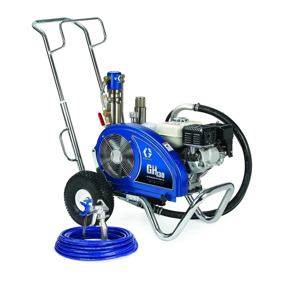
Page 5: Component Identification
Component Identification Item No. 311797F Component Hydraulic pump valve Pressure control Hydraulic Oil Cap Drain valve Engine ON/OFF switch Engine controls Electric motor On/Off Switch Gun trigger Lock Displacement pump ™ ProConnect Inlet strainer (standard) Inlet strainer (option) Serial number tag Component Identification... -
Page 6: General Repair Information
General Repair Information General Repair Information To reduce risk of serious injury, do not touch moving parts with fingers or tools while testing repair. Shut off sprayer when repairing. Install all covers, gaskets, screws and washers before operating sprayer 1. Keep all screws, nuts, washers, gaskets, and electrical fittings removed during repair procedures. -
Page 7: Maintenance
Pressure Relief Procedure The system pressure must be manually relieved to pre- vent the system from starting or spraying accidentally. Fluid under high pressure can be injected through the skin and cause serious injury. To reduce the risk of an injury from injection, splashing fluid, or moving parts, fol- low the Pressure Relief Procedure whenever you: •... -
Page 8: Troubleshooting
Troubleshooting PROBLEM Gas engine pulls hard (won't start) Gas engine does not start Gas engine doesn't work properly Gas engine operates, but displacement pump doesn't operate Displacement pump operates, but output is low on upstroke Displacement pump operates but output is low on downstroke and/or on both strokes Paint leaks and runs over side of wetcup... - Page 9 Notes Notes 311797F...
-
Page 10: Hydraulic Pump
Hydraulic Pump Removal Let hydraulic system cool before beginning service. 1. Relieve pressure, page 7. 2. Place drip pan or rags under sprayer to catch hydraulic oil that leaks out during repair. 3. Remove drain plug (2) and oil filter (227) and allow hydraulic oil to drain. - Page 11 Hydraulic Pump ti8821b 311797F...
- Page 12 Fan Belt Removal 1. Relieve pressure, page 7. 2. Loosen belt guard knob (55). 3. Rotate belt guard (117) up. 4. Lift engine (119) up to remove tension on belt (44). 5. Remove belt from pulley (43) and fan pulley (96). Fan Belt (Figure 3) Installation...
- Page 13 Removal NOTE: All service to the engine must be performed by an authorized HONDA dealer. 1. Relieve pressure, page 7. 2. Remove Fan Belt, page 10. 3. Loosen motor nut (205). Swing motor retainer bracket (204) out. 4. Remove engine (119) and rocker plate (99) from sprayer. 5.
-
Page 14: Hydraulic Motor Rebuild
Hydraulic Motor Rebuild Hydraulic Motor Rebuild Removal 1. Relieve pressure, page 7. 2. Place drip pan or rags under sprayer to catch hydraulic oil that leaks out during repair. 3. GH130 Models: - Follow Steps 2-5 of pump removal instructions, page 17. GH200, GH230, GH300 Models: - Follow Steps 4-8 of pump removal instructions, page 18. - Page 15 test hole ti8817A ti8818a 311797F...
-
Page 16: Hydraulic Oil/Filter Change
Hydraulic Oil/Filter Change Hydraulic Oil/Filter Change Removal 1. Relieve pressure, page 7. 2. Place drip pan or rags under sprayer to catch hydraulic oil that drains out. 3. Remove drain plug (2). page 26. Allow hydraulic oil to drain. 4. Unscrew filter (227) slowly - oil runs into groove and drains out rear. -
Page 17: Displacement Pump
See manual 311845 for pump repair instructions Removal 1. Flush pump. 2. Relieve pressure, page 7. 3. (Fig. 7) Remove suction tube (114) and paint hose (63) (remove at swivel end). 4. (Fig. 8) Push retaining ring (120) up; push out pin (92). 5. - Page 18 Displacement Pump ProConnect Displacement Pump ProConnect See pump manual 311845 for pump repair. Removal 1. Flush pump. 2. Relieve pressure, page 7. 3. (Fig. 13) Remove suction hose (114). . 13 4. (Fig. 14) Remove paint hose fitting (190) and paint hose (63) from pump fitting.
- Page 19 CAUTION Support pump with your hand before opening t-handle. 8. (Fig. 18) Open clamp (247). . 18 9. (Fig. 19) Remove pump (111) from unit. . 19 311797F Installation 1. (Fig. 20) If needed, place pump rod in adjustment casting and pull pump to lengthen rod.
- Page 20 Displacement Pump ProConnect 4. (Fig. 23) Install pin. . 23 5. (Fig. 24) Slide coupler cover (193) up to expose pump rod. Install rod couplers (179) over rod. . 24 6. (Fig. 25) Slide couple cover (193) down over rod couplers (179).
- Page 21 Notes Notes 311797F...
- Page 22 Parts All Sprayers Parts 150e 150f 150b 150c 150a 150d 150g 60 61 GH130 Model ti8822a 311797F...
- Page 23 Parts List - All Sprayers Part Description 112827 BUTTON,snap 119420 WHEEL,pneumatic, GH130 & 200 119408 WHEEl, pneumatic, GH230 & 300 156306 WASHER,flat, GH130 & 200 111841 WASHER, plain, 5/8, GH230 & 300 15C780 HANDLE, GH130 15C972 PIN, grooved, GH130 224807 BASE, valve, GH130 235014 VALVE, replacement, kit, GH130 61◆...
- Page 24 Parts Drawing - Engines Parts Drawing - Engines GH130, 200, 230 GH300 ti8813a 311797F...
- Page 25 Part Description 100023 WASHER,flat, GH130, 200 & 230 100132 WASHER, flat, GH300 113664 SCREW,cap,hex hd, GH130, 200 & 106212 SCHREW, cap, hex hd, GH300 110838 NUT,lock, GH130, 200 & 230 101566 NUT, lock, GH300 108842 SCREW,cap,hex hd, GH130, 200 & 116645 SCREW, cap, hex hd, GH300 112717 WASHER,GH130, 200 &...
- Page 26 Parts Drawing - All Sprayers Parts Drawing - All Sprayers ti8823b 311797F...
- Page 27 Parts List - All Sprayers Part Description 101754 PLUG 119433 BELT, GH130, 200, 230 119432 BELT, GH300 803298 SCREW, hex head 117284 GRILL, fan guard 15D862 NUT, hand 154594 O-RING 15E410 PULLEY, fan 15F157 BRACKET, mounting, engine, GH130, 200 & 230 15E583 BRACKET, mounting, engine, GH300 ▲...
- Page 28 Parts Drawing - All Sprayers Parts Drawing - All Sprayers GH200/230/300 GH130 ti8820a 311797F...
- Page 29 Parts List - All Sprayers Part Description 243814 HOSE, coupled 193031 NUT, retaining, GH130 15D000 CLIP, drain line 15J141 PIN, pump, GH130 288732 KIT, drain hose 241920 DEFLECTOR, threaded 288466 PUMP, kit, displacement, GH130 288467 PUMP, kit, displacement, GH200 288468 PUMP, kit, displacement, GH230 & 288251 HOSE,suction, GH130 288252 HOSE,suction, GH200, 230 &...
- Page 30 Parts Drawing - All Sprayers Parts Drawing - All Sprayers ti8824b 311797F...
-
Page 31: Parts List
Parts List Part Description ✓ 15B063 LABEL ▲◆ ▲◆ 15K430 LABEL, GH130 15K432 LABEL, GH200 15K434 LABEL, GH230 15K436 LABEL, GH300 239◆ 15H953 MANIFOLD, GH130 15J278 MANIFOLD, GH200 15J279 MANIFOLD, GH230 & 300 242◆ 15B564 SCREW, cap socket 243‡◆ 117739 WIPER, rod 244‡◆... - Page 32 GH 130 & 200 Sprayers with Spray Gun and Hoses GH 130 & 200 Sprayers with Spray Gun and Hoses Part No. Description 287036 KIT, gun, Contractor 3300 psi (227 bar, 22.7 MPa) Includes 202a - 202d 202a 243341 HOSE, grounded, nylon; 1/4 in. ID; cpld 1/4-18 npsm;...
-
Page 33: Technical Data
3300 1.25 GH 230 (227) (4.75) 3300 1.25 GH 300 (227) (4.75) Basic Sprayer Wetted Parts: Zinc and nickel-plated carbon steel, stainless steel, PTFE, acetal, chrome plating, leather, V-Maxt UHMWPE, alumi- num, stainless steel, tungsten carbide, ceramic, nylon, aluminum Engine 4.0 hp... -
Page 34: Graco Standard Warranty
Graco Standard Warranty Graco Standard Warranty Graco warrants all equipment referenced in this document which is manufactured by Graco and bearing its name to be free from defects in material and workmanship on the date of sale to the original purchaser for use. With the exception of any special, extended, or limited warranty published by Graco, Graco will, for a period of twelve months from the date of sale, repair or replace any part of the equipment determined by Graco to be defective.
Need help?
Do you have a question about the GH 300 and is the answer not in the manual?
Questions and answers