
Subscribe to Our Youtube Channel
Related Manuals for Kramer 713


Summary of Contents for Kramer 713
- Page 1 Kramer Electronics, Ltd. USER MANUAL Models: Video-Audio Line Transmitter 714-05 Video-Audio Line Receiver 714-10 Video-Audio Line Receiver 714-15 Video-Audio Line Receiver...
-
Page 2: Table Of Contents
Figure 5: Connecting the Video-Audio Line Transmitter/Receiver System Figure 6: CAT 5 PINOUT Tables Table 1: 713 Video-Audio Line Transmitter Front and Rear Panel Features Table 2: 714-05/714-10/714 -15 Front and Rear Panel Features Table 3: CAT 5 PINOUT Table 4: Technical Specifications of the 713 and the 714-05/714-10/714 -15... -
Page 3: Introduction
Our 1,000-plus different models now appear in 11 groups that are clearly defined by function. Congratulations on purchasing your Kramer 713 Video-Audio Line Transmitter and 714 Video-Audio Line Receiver which are ideal for: • Remote monitoring for CCTV, medical and schools •... -
Page 4: Getting Started
• Review the contents of this user manual • Use Kramer high performance, high resolution cables 2.1 Quick Start This quick start chart summarizes the basic setup and operation steps. 1 The complete list of Kramer cables is available from http://www.kramerelectronics.com KRAMER: SIMPLE CREATIVE TECHNOLOGY... -
Page 5: Overview
Overview Overview The 713 and 714 are a TP (Twisted Pair) transmitter and receiver for composite video and unbalanced stereo audio signals. The 713 transmitter converts composite video and stereo audio into a Twisted Pair (TP) signal and the 714 receiver converts the TP signal back to composite video, stereo audio and also provides an S/PDIF digital audio output. -
Page 6: Defining The 713/714 Video-Audio Line Transmitter/Receiver
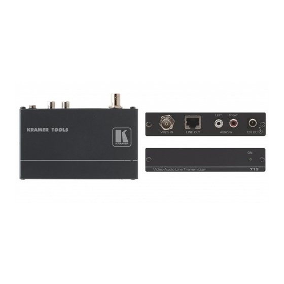
4.1 Defining the 713 Video-Audio Line Transmitter Figure 1 Table 1 define the front and rear panels of the 713 Video-Audio Line Transmitter. Figure 1: 713 Video-Audio Line Transmitter Front and Rear Panels Table 1: 713 Video-Audio Line Transmitter Front and Rear Panel Features... -
Page 7: Defining The 714 Video-Audio Line Receiver
Table 2: 714-05/714-10/714-15 Front and Rear Panel Features Feature Function V LED Lights green when video link from the 713 is established LINK LED A LED Lights green when audio link from the 713 is established Press to increase the signal equalization MANUAL EQ. -
Page 8: Figure 3: 714-10 Video-Audio Line Receiver Front Panel
Defining the 713/714 Video-Audio Line Transmitter/Receiver Figure 3: 714-10 Video-Audio Line Receiver Front Panel Figure 4: 714-15 Video-Audio Line Receiver Front Panel KRAMER: SIMPLE CREATIVE TECHNOLOGY... -
Page 9: Connecting The 713 And 714
VIDEO IN BNC connector, and connect the unbalanced stereo audio to the AUDIO IN LEFT and RIGHT AUDIO IN RCA connectors. 2. Using CAT 5 cabling, connect the LINE OUT RJ-45 connector on the 713 to the RJ-45 LINE IN connector on the 714. -
Page 10: Automatic And Manual Equalization
For most situations it is recommended that you leave the device in Auto mode. When the signal or the link between the 713 and the 714 is lost, pressing the Auto button once is sufficient to set the Auto mode. -
Page 11: Wiring The Cat 5 Line In/Line Out Rj-45 Connectors
Connecting the 713 and 714 5.2 Wiring the CAT 5 LINE IN/LINE OUT RJ-45 Connectors Table 3 Figure 6 define the CAT 5 pinout, using a straight pin-to-pin cable with RJ-45 connectors. When using STP cable, connect/solder the cable shield to the connector shield. -
Page 12: Technical Specifications
Technical Specifications Technical Specifications Table 4 lists the technical specifications of the 713 and the 714-05/714-10/714-15. Table 4: Technical Specifications of the 713 and the 714-05/714-10/714-15 714-05/714-10/714-15 INPUT: 1 RJ-45 CAT 5 connector (LINE IN) 1 composite 1Vpp/75Ω Video on a BNC connector... - Page 13 EXCLUSION OF DAMAGES The liability of Kramer for any effective products is limited to the repair or replacement of the product at our option. Kramer shall not be liable for: 1. Damage to other property caused by defects in this product, damages based upon inconvenience, loss of use of the product, loss of time, commercial loss;...
- Page 14 For the latest information on our products and a list of Kramer distributors visit www.kramerelectronics.com where updates to this user manual may be found. We welcome your questions, comments, and feedback. Safety Warning: Disconnect the unit from the power supply before opening/servicing.
Need help?
Do you have a question about the 713 and is the answer not in the manual?
Questions and answers