Table of Contents
Advertisement
Quick Links
Installation Manual Included (for qualified service personnel)
•
To assemble this unit, please refer to the Installation Manual on pages 14 through 39.
•
Before operating this unit, please read these instructions completely and keep them carefully for future
reference.
•
This unit is designed for installation by a qualified servicing dealer.
Installation performed by non-authorized individuals could cause safety-related problems with the operation of
this equipment.
For U.S.A. only:
•
To locate the closest authorized dealer in your area, please call 1-800-449-8989.
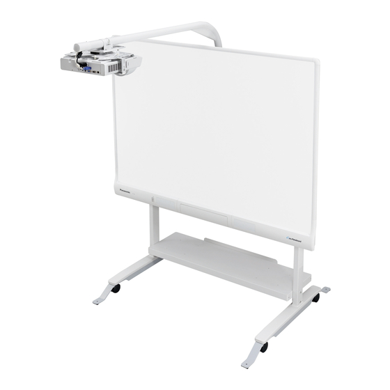
Operating Instructions
Up/Down Wall Mount Kit
Up/Down Stand Kit
(For elite Panaboard)
UE-608030
Model No.
UE-608031
UE-608032
Advertisement
Table of Contents

Related Manuals for Panasonic UE-608030


Summary of Contents for Panasonic UE-608030
- Page 1 Operating Instructions Up/Down Wall Mount Kit Up/Down Stand Kit (For elite Panaboard) UE-608030 Model No. UE-608031 UE-608032 Installation Manual Included (for qualified service personnel) • To assemble this unit, please refer to the Installation Manual on pages 14 through 39.
-
Page 2: Operating Instructions
Dealer’s address Dealer’s tel no. Exemption of Liability Panasonic System Networks Co., Ltd. is not responsible for accidents or injuries caused by, but not limited to, the following: 1. Altering the device or improper installation construction. 2. Using the device for purposes beyond its intended use. -
Page 3: Table Of Contents
Table of Contents Table of Contents Table of Contents Operating Instructions For Your Safety....................4 Usage......................7 Included Accessories....................... 7 Names and Uses of the Parts ....................7 Checkpoints When Installing the Equipment on the Table Plate ......... 8 Securing the Stand ........................9 Moving the elite Panaboard Up or Down ................ -
Page 4: For Your Safety
For Your Safety For Your Safety For Your Safety For Users To prevent severe injury and loss of life, read this section carefully before using the unit to ensure proper WARNING and safe operation of your unit. • This section explains the graphic symbols used in Installation and Relocation this manual. - Page 5 For Your Safety When items are to be placed on the table plate, put them toward the rear of the CAUTION board. Otherwise, they may be sandwiched between the table plate and elite Installation and Relocation Panaboard while the board is moving up or down, and this may damage the system.
- Page 6 For Your Safety Warning Label Side View !3" !1" !2" !4" Side View !5" !5" !6" !6" !1" !2" !3" !5" !4" !6" Operating Instructions...
-
Page 7: Usage
Usage Usage Included Accessories Check that the following item is included with your up/down wall kit or up/down stand kit. • Operating Instructions - - - 1 Names and Uses of the Parts ∫ ∫ When using with the stand When mounting onto a wall !1"... -
Page 8: Checkpoints When Installing The Equipment On The Table Plate
Usage Checkpoints When Installing the Equipment on the Table Plate There are limits on the dimensions of the equipment which can be placed on the table plate so check them out. Stand Part (Front) 1,150 mm (3 ft. 9 in.) Stand Part (Side) Notebook Computer 110 mm (4... -
Page 9: Securing The Stand
Usage Securing the Stand Note • The preceding height is the height of the elite Once you are satisfied with where the stand has been Panaboard unit. (Not including the height of the installed, lock the casters and secure the stand prior to projector arm.) use. -
Page 10: Using The Elite Panaboard
Usage Using the elite Panaboard The pin end stoppers are provided at points along the 450 mm (1 ft. 5 in.) adjustment range. Use them at points in the range from the highest point and at the Turn on the power of the computer and point where the elite Panaboard will be stopped by the projector. -
Page 11: Moving The Stand
Usage Moving the Stand Lower the elite Panaboard to the lowest point. Stowing the Projector Assembly Note • Prepare to move the stand by carrying out the steps below. If the height of the entrance is less than 2 m (6 ft. -
Page 12: Moving The Stand
Usage Removing the Foot Reinforcing Notice Assemblies When moving the stand • Release the lock lever for each caster. While grasping the release lever on the back side of • Before moving the stand, disconnect the plug of the each foot reinforcing assembly, pull the assembly from table tap from the wall outlet. -
Page 13: Appendix
Appendix Appendix Troubleshooting Symptom Possible cause and solution Unusual sounds are heard while the elite Panaboard is moving Something may be wrong with the up/down unit. Stop using the elite up or down or the elite Panaboard immediately, and contact your dealer. Panaboard feels extremely heavy when it is raised. -
Page 14: Installation Manual (For Qualified Service Personnel)
Request assembly of the units and wall mounting from your dealer. • Before constructing or installing the units, please read “Installation Manual (for qualified service personnel)” carefully. Panasonic System Networks Co., Ltd. cannot be held responsible for accidents or damage to property resulting from incorrect installation. •... - Page 15 For Your Safety Safety Be careful around the projector ventilation area, which becomes hot. CAUTION Working in this area or touching nearby objects may cause injury. Do not attach the electronic board to mortared walls. Accidental electric leakage from the mounting bolts securing the up/down unit to metal laths or wire laths can cause heat, smoke or fire.
-
Page 16: Product Configuration
Up/Down Unit UE-608030 Short-Throw Arm Unit UE-608032 Included Accessories The following items are provided in the packing boxes. Check that they are present and accounted for. ∫ Up/Down Unit (UE-608030) Unit × 1 Part Name Illustration Q’ty Part Name Illustration Q’ty... - Page 17 Product Configuration ∫ Stand Table Unit (UE-608031) Stand × 2 Table Plate × 1 Protective Cover × 1 Foot Reinforcing Assembly × 4 Part Name Illustration Q’ty Part Name Illustration Q’ty Collar for Securing Bolt (M6 x 75 mm [2 in.]) for Table Plate Securing Left and Right Stands...
-
Page 18: Wall Mounting Construction
Wall Mounting Construction Wall Mounting Construction Checking the Wall Which method should be used to mount the up/down wall mount kit depends greatly on the structure of the wall. The system to be mounted on the wall is heavy (up to 84 kg [185.19 lbs] including the elite Panaboard and projector). Before proceeding with installation, therefore, consult with the building manager, maintenance engineer or designer to verify that the wall has a structure strong enough to support the weight of the system. - Page 19 Wall Mounting Construction Concerning Installation • The up/down stand kit and up/down wall mount kit are for indoor use. They cannot be used outdoors. Neither can they be installed or used in the following kinds of places. — Places where they will be directly exposed to rain or water (including under the eaves of a house) —...
-
Page 20: Wall Types And Installation Procedures
UB-T880W / UB-T781W 2,500 mm 2500 mm Projector (8 ft. 2 in.) 438 mm 438 mm Panasonic 420 mm (1 ft. 4 in.) (1 ft. 5 in.) SANYO 567 mm (1 ft. 10 in.) EPSON 410 mm (1 ft. 4 in.) - Page 21 Wall Mounting Construction Notice • Ensure that the installation strength is at least as great as the Installation specified pull-out strength of the anchors which is 5,197.5 N Surface Anchor [530 kgf]. (internal thread) • Use the values recommended by the manufacturer of the anchors At least 1.5 times used for the depth to which the anchors are to be embedded in the the bolt diameter...
- Page 22 Wall Mounting Construction <Concerning the Reinforcing Material Work> If the wall backing materials are not principal structural components, they must be reinforced as below. Install the reinforcing material onto the wall backing materials. If the distance between the wall backing material is not less than 910 mm (2 ft.
- Page 23 Wall Mounting Construction III. When the Principal Structural Components are in Close Proximity to the Wall Backing Materials (when there is no distance between the backing materials and principal structural components) Concrete or Other Principal Structural Component Inside Wall Concrete or Other Principal Structural Component Indoor...
-
Page 24: Mounting And Securing The Up/Down Unit
Tighten the M8 bolts in the top holes of the left and right pipes, and fasten the up/down unit securely to the wall. Panasonic PT-ST10 SANYO LP-WXL46(S) Stay Drum 75 Pipe Stay L75... - Page 25 Move the projector bracket, move the adjustment Initial Projector model name spacers feet of the projector to the positions shown in the “P” Panasonic PT-ST10 figure below, then align the positions of the spacers with the holes for fastening the projector, “S” SANYO LP-WXL46(S) and use the screws to fasten the projector.
-
Page 26: Mounting The Projector Arm
Wall Mounting Construction Mounting the Projector Arm Align the projector sub-bracket so that the projector fits in between, and secure both ends using the toothed washers (J) and the screws Pass the power cable used for the projector (D) for securing the projector sub-bracket. and the video cable through the projector arm. - Page 27 The position where the knob is to be secured Mount the projector bracket, on which the projector depends on the projector which is going to be unit has been mounted, onto the projector arm. used. Top position Panasonic PT-ST10 EPSON EB-410W Center Acer S1200 position BenQ...
-
Page 28: Adjusting The Up/Down Unit
Wall Mounting Construction Adjusting the Up/Down Unit Route and connect the power cable and video cable, which have already been passed through the projector arm, to the projector, and Align the position of the hold tube assembly, to which secure the pipe cap (G) using the screw (H) the gas spring is secured, with the elite Panaboard for securing the pipe cap. - Page 29 When any other projector is going to be used, move it from the position shown above by the dimensions given below. + 147 mm – 147 mm Panasonic (+ 5 in.) (– 5 in.) + 157 mm – 157 mm...
- Page 30 Wall Mounting Construction After removing the up/down locking plates Notice attached to both sides of the up/down unit, secure • Even when the elite Panaboard has been placed the elite Panaboard at the highest position. on the up/down unit, it has still not been secured •...
- Page 31 Wall Mounting Construction Confirm that the M6 189 bolt and nuts A and B Holding nut B in place with a 10 mm ( in.) are in the correct positions. (The direction of wrench, use another wrench to turn the M6 189 rotation in instructions is relative to the part screw clockwise, and then move nut B about being adjusted as viewed from above.)
- Page 32 Wall Mounting Construction Turn the head of the M6 189 screw with a 10 mm Holding nut B in place with a 10 mm ( in.) in.) wrench (ratchet type) and reposition the wrench, use another wrench to turn the M6 189 hold tube assembly to the adjustment position screw counterclockwise.
-
Page 33: Mounting The Elite Panaboard
Wall Mounting Construction Mounting the elite Checking the Up/Down Panaboard Operations • Confirm that the up/down part can easily be lifted Align the wall mount holes on the bottom of the higher than the pin end stopper. board attachments with the left and right •... -
Page 34: Wiring Connections
Wall Mounting Construction Wiring Connections Apply the High-Temperature Warning Label Position the computer which you are going to use at the prescribed location, and connect the computer, projector and elite Panaboard as Turn on the power of the computer, projector shown below. -
Page 35: Projection Adjustments
Wall Mounting Construction Projection Adjustments ∫ Adjusting the Projection Position If the image of the projector is projected too far toward the top or bottom, turn the knob on the Project an image from the projector onto the projector bracket, and adjust. screen of the elite Panaboard. -
Page 36: Securing The Elite Panaboard
Wall Mounting Construction Securing the elite Checking the Operations Panaboard of the elite Panaboard For details of cleaning the screen and checking the Tighten the two-wing bolts used to secure the operations of the elite Panaboard, refer to the board bottom bracket, and secure the elite Operating Instructions of the elite Panaboard. -
Page 37: Assembling The Stands
Assembling the Stands Assembling the Stands Assembling the Stands Notice • Mount the stands with the sides provided with Assembling the Stand Table Unit the locking casters pointed upward. Take the left stand and right stand out of the Tighten bolts A. stand unit box, and use the three bolts and •... - Page 38 Assembling the Stands Pull up the pipe part of the stand by hand while After attaching the left and right stands, place tightening bolts B and C in this order. the assembled parts upright, and check that there is no play either at the front or back or at Notice the left or right.
-
Page 39: Attaching The Protective Cover
Assembling the Stands Preparing to Mount the Projector Securing the Up/Down Stand Kit → Refer to “Preparing to Mount the Projector” When using the system with the up/down stand kit, the (page 24) under “Wall Mounting Construction”. system may fall over if a child should hang or swing Mounting the Projector Arm from the projector arm, for example. - Page 40 For users in Turkey Türkiye’deki kullanıcılar için EEE Complies with Directive of Turkey. EEE Yönetmeliğine Uygundur. © Panasonic System Networks Co., Ltd. 2010 PJQXC0341YA-F F0710MH2110...
Need help?
Do you have a question about the UE-608030 and is the answer not in the manual?
Questions and answers