Table of Contents
Advertisement
Quick Links
Advertisement
Table of Contents

Subscribe to Our Youtube Channel
Related Manuals for Kramer TP-310A


Summary of Contents for Kramer TP-310A
-
Page 1: User Manual
Kramer Electronics, Ltd. USER MANUAL Model: TP-310A UXGA Line Receiver/DA... -
Page 2: Table Of Contents
Technical Specifications Figures Figure 1: TP-310A UXGA Line Receiver/DA Figure 2: TP-310A Underside Figure 3: Connecting the TP-310A UXGA/Line Receiver – DA system Figure 4: Distributing the Signal to 37 Receivers Figure 5: CAT 5 PINOUT Figure 6: RS-232 PINOUT Connection... -
Page 3: Introduction
2 We recommend that you use only the power cord supplied with this device 3 Download up-to-date Kramer user manuals from our Web site at http://www.kramerelectronics.com 4 The complete list of Kramer cables is on our Web site at http://www.kramerelectronics.com... -
Page 4: Quick Start
Getting Started Quick Start This quick start chart summarizes the basic setup and operation steps. KRAMER: SIMPLE CREATIVE TECHNOLOGY... -
Page 5: Overview
The TP-310A also decodes the CAT 5 signal and simultaneously distributes it to two UXGA outputs, two analog audio outputs, two digital audio outputs and two RS-232 outputs. The TP-310A serves as a power center that can distribute power to both the transmitter and the connected receivers (see section 3.1). -
Page 6: Shielded Twisted Pair (Stp)/Unshielded Twisted Pair (Utp)
We recommend that you use Shielded Twisted Pair (STP) cable. There are different levels of STP cable available, and we advise you to use the best quality STP cable that you can afford. Our non-skew-free cable, Kramer BC-STP is intended for analog signals where skewing is not an issue. For cases where there is skewing, our UTP skew-free cable, Kramer BC-XTP, may be used. -
Page 7: Figure 1: Tp-310A Uxga Line Receiver/Da
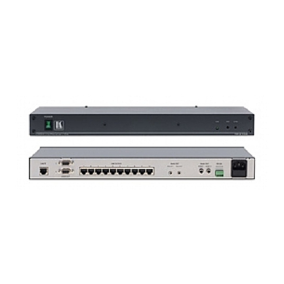
Your TP-310A UXGA Line Receiver/DA Figure 1: TP-310A UXGA Line Receiver/DA... -
Page 8: The Tp-310A Uxga Line Receiver/Da Underside
2 Use a screwdriver to carefully rotate the trimmer, adjusting the appropriate level 3 The PINOUT is defined in Table 3 Figure 5 4 Using a Kramer's skew-free CAT 5 cable BC-SXTP, for example, with RJ-45 connectors at both ends (the PINOUT is defined in Table 3 Figure... -
Page 9: Installing In A Rack
Installing in a Rack Installing in a Rack This section provides instructions for rack mounting the 1U unit. -
Page 10: Configuring The Tp-310A Uxga Line Receiver/Da
2 Using up to 300ft (100m) of UTP cabling 3 Switch OFF the power on each device before connecting it to your TP-310A. After connecting your TP-310A, switch on its power and then switch on the power on each device 4 Not supplied. - Page 11 300ft (up to 100m)) 4. Connect the LINE OUTPUT RJ-45 connector on the TP-123 to the LINE IN RJ-45 connector on the TP-310A, via STP cabling (with a range of up to 300ft (up to100m)), see section 3.2.
-
Page 12: Figure 3: Connecting The Tp-310A Uxga/Line Receiver - Da System
Configuring the TP-310A UXGA Line Receiver/DA Figure 3: Connecting the TP-310A UXGA/Line Receiver – DA system KRAMER: SIMPLE CREATIVE TECHNOLOGY... -
Page 13: Connecting Additional Tp-310A Uxga Line Receiver/Da Units
To connect an expanded UXGA Line Receiver/DA system, do the following: 1. Connect a transmitter to the LINE IN RJ-45 connector of the first TP-310A. 2. Connect the LINE OUTPUT 1 RJ-45 connector of the first TP-310A to the LINE IN RJ-45 connector of the second TP-310A. -
Page 14: Figure 4: Distributing The Signal To 37 Receivers
Configuring the TP-310A UXGA Line Receiver/DA Transmitter TP-46 TP-46 TP-122 TP-124 TP-122 TP-122 TP-124 TP-124 Figure 4: Distributing the Signal to 37 Receivers KRAMER: SIMPLE CREATIVE TECHNOLOGY... -
Page 15: Wiring The Cat 5 Line In / Line Out Rj-45 Connectors
Configuring the TP-310A UXGA Line Receiver/DA Wiring the CAT 5 LINE IN / LINE OUT RJ-45 Connectors Table 3 Figure 5 define the UTP CAT 5 PINOUT, using a straight pin to pin cable with RJ-45 connectors: Figure 5: CAT 5 PINOUT... -
Page 16: Technical Specifications
Technical Specifications Technical Specifications Table 5 includes the technical specifications of the TP-310A: Table 5: Technical Specifications of the TP-310A UXGA Line Receiver/DA INPUT: 1 RJ-45 TP LINE IN connector OUTPUTS: 10 RJ-45 TP LINE OUT connectors 2 UXGA Video out connectors 2 3.5mm mini jack audio out connectors... - Page 17 EXCLUSION OF DAMAGES The liability of Kramer for any effective products is limited to the repair or replacement of the product at our option. Kramer shall not be liable for: 1. Damage to other property caused by defects in this product, damages based upon inconvenience, loss of use of the product, loss of time, commercial loss;...
- Page 18 For the latest information on our products and a list of Kramer distributors, visit our Web site: www.kramerelectronics.com, where updates to this user manual may be found. We welcome your questions, comments and feedback. Safety Warning: Disconnect the unit from the power supply before opening/servicing.
Need help?
Do you have a question about the TP-310A and is the answer not in the manual?
Questions and answers