
Subscribe to Our Youtube Channel
Related Manuals for V-Tec VT596/KP


Summary of Contents for V-Tec VT596/KP
- Page 1 VT596(F)/KP USER MANUAL(EN) 4 Wire Video Intercom System VT596/KP VT596F/KP Read this manual carefully before using the product, and keep it well for future use. ...
-
Page 2: Parts And Functions
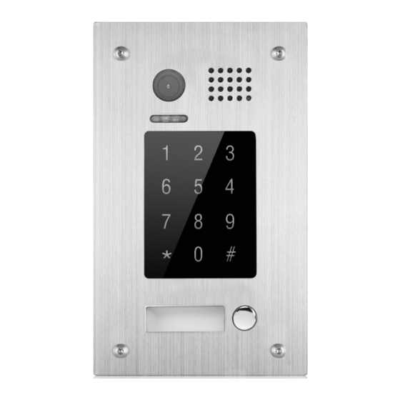
1. Parts and Functions Camera Lens Speaker Indicator(red) Indicator(blue) Touch Sensitive Digital Keypad 28 mm Nameplate Call Button Microphone Rainy Cover VT596/KP 90 mm Camera Lens Speaker Indicator(red) Indicator(blue) Touch Sensitive Digital Keypad Nameplate Call Button Screws for panel mounting... -
Page 3: Door Station Mounting
• • 4B:•Talk•and•control•signal•(Audio•signal) • • PL:•External•lock•power•input,•connect•to•the•power•positive(power•+). • • S+:•Lock•power(+)•output. • • S-:•Lock•power(-)•output. 3. Door Station Mounting VT596/KP Mounting adjust camera angle 4 core cable Drill holes in the wall to match the size of Connect the cable correctly and adjust screws and attach the rainy cover to the wall. -
Page 4: Placing Name Label
VT596F/KP Mounting adjust camera angle 4 core cable Drill a hole in the wall to match the size of the Connect the cable correctly and adjust mounting box and attach to the wall. right angle for camera Attach the panel to the mounting box and Place name label use screws supplied to fix the panel Placing Name Label... -
Page 5: System Wiring And Electric Lock Connection
4. System Wiring and Electric Lock Connection Basic Connection AC ~ TO Monitor JS/OS1 Shielding Layer of the RVVP Cable Electric Lock Connection • • Mode1:Door•Lock•Controlled•With•Dry•Contact Must•install•external•power•supply•for•lock,and•nearly•all•kinds•of•electronic•lock•can•be•used.Incidentally,in• this•mode,you•can•continue•talking•and•monitoring•during•unlock•operation. Note:• 1.The•external•power•supply•must•be•used•according• Connect to Monitor to•the•lock. 2.The•inside•relay•contact•is•restricted•to•AC•or•DC• AC ~ VT596(F) 24V/1A. Take off JP/LK Jumper 3.The•jumper•must•be•taken•off•before•connecting. -
Page 6: Functions Setting Up
• • Mode2:Door•Lock•Controlled•With•Internal•Power The•lock•can•be•directly•connected•with•the•door•station•and•the•power•through•monitor.During•unlock• operation,the•monitor•will•close•screen•automatically. Note: Connect to Monitor 1.Electronic•lock•of•power-on-to-unlock•shoule•be• used. 1 2 3 JP/LK Jumper position in 2.The•door•lock•is•limited•to•12V,and•holding•current• Unlock mode:0 AC ~ VT596(F) must•be•less•than•250mA 3.The• door• lock• control• is• not• timed• from• Exit• Button(EB). 4.•The•Unlock•Mode•Parameter•of•Monitor•must•be• set•to•0•(by•default). LOCK 5. Functions Setting Up This•section•explains•the•settings•of•each•function,please•refer•to•the•following•table: About•the•setting•mode: Input•the•master•code•to•switch•to•the•setting•mode,•and•input•the•corresponding•setting•code•to•perform•... - Page 7 Order Setting items Setting range Default value Setting code Reset•all•settings 1234 1•~•12•digits Setting•the•master•code 1234 Valid•keys:0•~•9 Setting•the•key 10•to•99•seconds/ 10•seconds illumination•time continually•lit(00s) Setting•the•unlock•time 01•to•99•seconds 1•seconds Setting•the•unlock• •0:opened/1:closed opened mode Operation•tone•settings 0:on/1:off Reset•code•settings 1234 &#•function•settings 0:Normal/1:Reverse Normal Reserve Reserve Reserve Interference•resistant•• Valid•keys:0•~•5 grade•settings Reserve Reserve Reserve...
-
Page 8: Setting Items
Setting items 1.Reset all settings 2.Setting the master code 3.Setting the key 4.Setting the illumination time unlock time (Default 1234) (Default 10s) (Default 1s) Step 1 Step 1 Step 1 Step 1 (red) (blue) Input the master code. (Default: [ ] +[#] ) Beep+, Beep Step 2... - Page 9 Setting items 5.Setting the unlock mode 6.Setting operation tone 8. &# function setting 7.Reset code setting (Default 0(opened)) (Default ON) (Default Normal) Step 1 Step 1 Step 1 Step 1 (red) (blue) Input the master code. (Default: [ ] +[#]) Beep+, Beep Step 2 Step 2...
- Page 10 Setting items 10.Interference resistant 12.Setting the code 13.Setting the code 14.Setting the code grade setting forTemporary1 forTemporary2 for user (Default 2) Step 1 Step 1 Step 1 Step 1 (red) (blue) Input the master code. (Default: [ ]+[#] ) Beep+, Beep Step 2 Step 2 Step 2...
-
Page 11: Unlock Operations
-10- 6. Unlock Operations Unlocking of user code When•the•registered•user•code•has•been•input•using•the•keypad•(1~12•digits),•the•LED•indicator•(red)•lights• up,•the•buzzer•sounds,and•the•electric•door•strike•is•unlocked.(note•that•you•should•press•"#"•button(if•"#"• button•is•set•to•confirm•button)•after•input•the•unlock•code) Example:• Unlock code=2011 Red LED lights up (during relay1 operation) (red) (blue) Beep+ • • The•time•interval•during•which•the•button•must•be•pressed•is•approximately•10•seconds.•If• the•time•interval•exceeds•approximately•10•seconds,•the•input•value•will•be•cleared. • • If•you•make•a•mistake•when•inputting•the•user•code,press•the"•cancel"•button•and•input•the• user•code•again. • • If•10•times•incorrect•access•codes•are•continuously•attempted,•the•release•function•is• forbidden•and•the•input•operation•is•disabled•for•60•seconds•.•During•this•time,the•buzzer•will• continuously•sound•about•8•times. • • You•can•activate•the•electric•door•strike•by•pressing•the•request•to•exit•button•connected•to• the•unit.•(The•unlock•function•will•work•when•the•request•to•exit•button•is•pushed,•even•while•... -
Page 12: Specifications
-11- 7. Precaustions • • Please•clean•the•unit•with•soft•cotton•cloth,•don't•use•the•organic•impregnant•or•chemical• clean•agent.•If•necessary,•please•use•a•little•pure•water•or•dilute•soap•water•to•clean•the•dust. • • The•unit•is•weather•resistant.•However•do•not•spray•high•pressure•water•on•access•control• keypad•directly.•Excessive•moisture•may•cause•problems•with•the•unit. • • You•must•use•the•right•adaptor•which•is•supplied•by•the•manufacture•or•approved•by•the• manufacture.. • • Pay•attention•to•the•high•voltage•inside•the•products,•please•refer•service•only•to•a•trained• and•qualified•professional. 8. Specifications • • Power•Supply•:•• • • • DC•16~20V• • • Power•Consumption:•• • • Standby•0.5W;•Working•status•3W; • • Camera:•• • • • Pinhole•Sharp•Color•CCD;...
Need help?
Do you have a question about the VT596/KP and is the answer not in the manual?
Questions and answers