Table of Contents
Advertisement
Cisco VG350 Voice Gateway Hardware
Installation Guide
THE SPECIFICATIONS AND INFORMATION REGARDING THE PRODUCTS IN THIS MANUAL ARE SUBJECT TO
CHANGE WITHOUT NOTICE. ALL STATEMENTS, INFORMATION, AND RECOMMENDATIONS IN THIS
MANUAL ARE BELIEVED TO BE ACCURATE BUT ARE PRESENTED WITHOUT WARRANTY OF ANY KIND,
EXPRESS OR IMPLIED. USERS MUST TAKE FULL RESPONSIBILITY FOR THEIR APPLICATION OF ANY
PRODUCTS.
Americas Headquarters
Cisco Systems, Inc.
170 West Tasman Drive
San Jose, CA 95134-1706
USA
http://www.cisco.com
Tel: 408 526-4000
800 553-NETS (6387)
Fax: 408 527-0883
Last Revised: December 5, 2012
Text Part Number: OL-25970-01
Advertisement
Table of Contents

Related Manuals for Cisco VG350


Summary of Contents for Cisco VG350
- Page 1 Cisco VG350 Voice Gateway Hardware Installation Guide THE SPECIFICATIONS AND INFORMATION REGARDING THE PRODUCTS IN THIS MANUAL ARE SUBJECT TO CHANGE WITHOUT NOTICE. ALL STATEMENTS, INFORMATION, AND RECOMMENDATIONS IN THIS MANUAL ARE BELIEVED TO BE ACCURATE BUT ARE PRESENTED WITHOUT WARRANTY OF ANY KIND, EXPRESS OR IMPLIED.
- Page 2 OR ITS SUPPLIERS HAVE BEEN ADVISED OF THE POSSIBILITY OF SUCH DAMAGES. Cisco and the Cisco logo are trademarks or registered trademarks of Cisco and/or its affiliates in the U.S. and other countries. To view a list of Cisco trademarks, go to this URL: www.cisco.com/go/trademarks.
- Page 3 Submitting a Service Request -xvii Definitions of Service Request Severity -xvii Obtaining Additional Publications and Information -xviii Overview of the Cisco VG350 Voice Gateway C H A P T E R Overview VG350 Voice Gateway Chassis Configuration Options Interfaces and Service Capabilities...
-
Page 4: Table Of Contents
Gigabit Ethernet Maximum Distance FXS Analog Voice Port Maximum Distance FXS-E (Extended loop) Analog Voice Port Maximum Distance Interference Considerations Installing the Cisco VG350 Voice Gateway C H A P T E R Safety Recommendations Cisco VG350 Voice Gateway Hardware Installation Guide OL-25970-01... - Page 5 Preventing Electrostatic Discharge Damage Site Log Keeping Track–Checklist Installation Checklist Mounting Tools and Equipment Unpacking and Inspection Powering On the Cisco VG350 Voice Gateway C H A P T E R Checklist for Power-On Power-On Procedure Troubleshooting Cable Specifications and Information...
-
Page 6: A P P E N D I X A Cable Specifications And Information
Audience This publication is designed for experienced IT technicians familiar with Cisco products, IOS CLI, and concepts and technologies of networking. This document can also be used by experienced telecommunications administrators familiar with Cisco Unified Communications Manager and/or Cisco Unified Communications Manager Business Edition and/or Cisco Unified Communications Manager Express. - Page 7 Means the following information will help you solve a problem. The tips information might not be troubleshooting or even an action, but could be useful information, similar to a Timesaver. Cisco VG350 Voice Gateway Hardware Installation Guide viii OL-25970-01...
-
Page 8: Safety Warnings
Safety warnings appear throughout this publication in procedures that, if performed incorrectly, may harm you. A warning symbol precedes each warning statement. To see translations of the warnings that appear in this publication, refer to Cisco VG350 Voice Gateway Regulatory Compliance and Safety Information. Warning Definition... - Page 9 Al final de cada advertencia encontrará el número que le ayudará a encontrar el texto traducido en el apartado de traducciones que acompaña a este dispositivo. GUARDE ESTAS INSTRUCCIONES Cisco VG350 Voice Gateway Hardware Installation Guide OL-25970-01...
- Page 10 Använd det nummer som finns i slutet av varje varning för att hitta dess översättning i de översatta säkerhetsvarningar som medföljer denna anordning. SPARA DESSA ANVISNINGAR Cisco VG350 Voice Gateway Hardware Installation Guide OL-25970-01...
- Page 11 Brug erklæringsnummeret efter hver advarsel for at finde oversættelsen i de oversatte advarsler, der fulgte med denne enhed. GEM DISSE ANVISNINGER Cisco VG350 Voice Gateway Hardware Installation Guide OL-25970-01...
- Page 12 Contents Cisco VG350 Voice Gateway Hardware Installation Guide xiii OL-25970-01...
- Page 13 Contents Cisco VG350 Voice Gateway Hardware Installation Guide OL-25970-01...
-
Page 14: Related Documentation
Release 15.2(4)M New Features and Important Notes • 1. Refer to the modular reference publications that correspond to the Cisco IOS software release installed on your Cisco VG350 Voice Gateway. Obtaining Documentation Cisco documentation and additional literature are available on Cisco.com. Cisco also provides several ways to obtain technical assistance and other technical resources. -
Page 15: Ordering Documentation
Access to all tools on the Cisco Technical Support Website requires a Cisco.com user ID and password. If you have a valid service contract but do not have a user ID or password, you can register at this URL: http://tools.cisco.com/RPF/register/register.do... - Page 16 URL: http://www.cisco.com/techsupport/servicerequest For S1 or S2 service requests or if you do not have Internet access, contact the Cisco TAC by telephone. (S1 or S2 service requests are those in which your production network is down or severely degraded.) Cisco TAC engineers are assigned immediately to S1 and S2 service requests to help keep your business operations running smoothly.
- Page 17 Cisco Marketplace, the company store, at this URL: http://www.cisco.com/go/marketplace/ • The Cisco Product Catalog describes the networking products offered by Cisco Systems, as well as ordering and customer support services. Access the Cisco Product Catalog at this URL: http://cisco.com/univercd/cc/td/doc/pcat/ •...
- Page 18 • Software Elements, page 1-9 • Overview The Cisco VG350 service module is a high-density analog voice gateway. It is an intermediate path that enables TDM to IP transition. The Cisco VG350 Voice Gateway supports the following interfaces: • Gigabit Ethernet (GE) •...
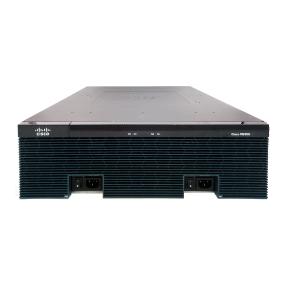
- Page 19 Chapter 1 Overview of the Cisco VG350 Voice Gateway VG350 Voice Gateway Chassis VG350 Voice Gateway Chassis The following figures show the front and back panels of the VG350 Voice Gateway Chassis: Figure 1-1 shows the Front Panel. • Figure 1-2 shows the Back Panel.
-
Page 20: Configuration Options
10/100/1000 Ethernet port GE 0/0 10 SM-D-48FXS-E Service Module Configuration Options The following configuration options are available for Cisco VG350 Voice Gateway: Table 1-1 Configuration Options Possible with Cisco VG350 Voice Gateway with the Double-Wide High Density Analog Service Module (DWSM) -
Page 21: Led Indicators
Overview of the Cisco VG350 Voice Gateway Physical Description and LEDs Physical Description and LEDs LED Indicators Table 1-3 describes the LED indicators for the Cisco VG350. Table 1-3 LED Indicators for Cisco VG350 Color Description Location on the VG350... - Page 22 Chapter 1 Overview of the Cisco VG350 Voice Gateway Physical Description and LEDs Table 1-3 LED Indicators for Cisco VG350 (continued) Color Description Location on the VG350 CF0/CF1 Green Flash memory is being accessed; Back panel do not eject the CompactFlash memory card.
-
Page 23: Specifications
Chapter 1 Overview of the Cisco VG350 Voice Gateway Physical Description and LEDs Specifications Table 1-4 details the technical specifications of the Cisco VG350 Voice Gateway. Table 1-4 Cisco VG350 Voice Gateway Technical Specifications Description Specification Physical Dimensions (H x W x D) 5.22 x 17.25 x 18.75 in. - Page 24 Chapter 1 Overview of the Cisco VG350 Voice Gateway Physical Description and LEDs Table 1-4 Cisco VG350 Voice Gateway Technical Specifications (continued) Description Specification Temperature 23 to 122°F (–5°C to 50°C) (short-term per NEBS/1800m max altitude) Operating altitude maximum 13,123 ft (4000 m) For China, the unit cannot operate above 2000 m.
- Page 25 Chapter 1 Overview of the Cisco VG350 Voice Gateway Physical Description and LEDs Table 1-4 Cisco VG350 Voice Gateway Technical Specifications (continued) Description Specification Immunity compliance CISPR24 ITE-Immunity characteristics, Limits and methods of measurement • EN 55024 ITE-Immunity characteristics, Limits and methods ofmeasurement •...
-
Page 26: Software Elements
Overview of the Cisco VG350 Voice Gateway Software Elements Software Elements The operating system for the Cisco VG350 Voice Gateway is the Cisco IOS software that resides in flash memory. Configuration Connections You can use an ASCII terminal or a PC to configure a Cisco VG350 Voice Gateway. The configuration can be performed in several ways: •... - Page 27 Chapter 1 Overview of the Cisco VG350 Voice Gateway Software Elements Cisco VG350 Voice Gateway Hardware Installation Guide 1-10 OL-25970-01...
- Page 28 This chapter provides information about the following Double-Wide High Denstiy Analog Service Module (DWSM). Cisco SM-D-72FXS Service Module—A 72 FXS port DWSM with 4 out of the 72 ports supporting OPX ‘Lite’ capabilities. Cisco SM-D-48FXS-E Service Module—A 48 FXS port DWSM with all 48 ports supporting OPX Lite capabilities.
-
Page 29: Double-Wide High Density Analog Service Module Overview
The modules can be plugged in the following DWSM slots of the following platforms: On Cisco 3945 and Cisco 3945e - only on slot 4. • • On Cisco 3925, Cisc0 3925e and Cisco 2951 - only on slot 2. Table 2-1 shows the comparison between Cisco SM-D-72FXS and SM-D-48FXS-E. Table 2-1... -
Page 30: Installing Sm-D-72Fxs
Installing Cisco Interface Cards in Cisco Access Routers document. Cables The VG350 Voice Gateway uses RJ-21 cables to connect to a distribution box. Warning To avoid electric shock, do not connect safety extra-low voltage (SELV) circuits to telephone-network voltage (TNV) circuits. LAN ports contain SELV circuits, and WAN ports contain TNV circuits. Some LAN and WAN ports both use RJ-45 connectors. -
Page 31: Installing Sm-D-48Fxs-E
Installing Cisco Interface Cards in Cisco Access Routers document. Cables The VG350 Voice Gateway uses RJ-21 cables to connect to a distribution box. Warning To avoid electric shock, do not connect safety extra-low voltage (SELV) circuits to telephone-network voltage (TNV) circuits. LAN ports contain SELV circuits, and WAN ports contain TNV circuits. Some LAN and WAN ports both use RJ-45 connectors. -
Page 32: Fxo Fail-Over Bypass Ports
FXO I/F To PSTN To external PSTN to external FXO PSTN to RJ-21 BYPASS-1 FXO Interface Interface connector Port 47 (optional) FXS Port 47 to RJ-21 No connection to connector external FXO I/F Cisco VG350 Voice Gateway Hardware Installation Guide OL-25970-01... -
Page 33: Cisco Sm-D-72Fxs Service Module Specifications
Physical Description and LEDs All interface ports and LEDs are on the rear of the chassis. Figure 2-2 illustrates their locations. Figure 2-2 Cisco SM-D-48FXS-E Service Module LEDs EN LED FXO Bypass ports Cisco VG350 Voice Gateway Hardware Installation Guide OL-25970-01... -
Page 34: Port Numbering Conventions
Note Online Insertion and Removal The DWSM can be hot-inserted into the VG350 Voice Gateway without any potential of electrical damage either to the SM or the Host because the Online Insertion and Removal (OIR) logic is present on all SM designs. -
Page 35: Insertion And Removal Steps
Each Service Module(SM) has an Enable LED that is mounted on the SM and visible through the faceplate of the SM. The EN LED includes: Green / Amber Dual Color LED • Defaults to OFF / ON power up • Cisco VG350 Voice Gateway Hardware Installation Guide OL-25970-01... -
Page 36: Chapter 3 Planning Your Installation
• Temperature Control and Ventilation The installation location (room, closet, or cabinet) for the Cisco VG350 Voice Gateway should always be well ventilated and provide adequate air circulation to ensure proper cooling. The room temperature should be maintained between 32 to 122°F (0 to 50°C). -
Page 37: Enclosed Racks
If the Cisco VG350 Voice Gateway is installed in an enclosed rack with a ventilation fan at the top, make sure that heated air drawn upward from other equipment does not prevent adequate cooling. -
Page 38: Power Source
To handle power failure conditions, an uninterrupted power supply (UPS) is needed. UPS is widely available in all markets, including emerging markets (due to prevalence of UPS for personal computers). Thus, a separate UPS for Cisco VG350 Voice Gateway is a viable option when the ISR/UPS is not co-located with it. -
Page 39: Cable Types
Planning Your Installation Distance Limitations for Interface Cables Cable Types The cable types that are used are dependent on the Cisco VG350 Voice Gateway that you are using. For more information, see the “Interfaces and Service Capabilities” section on page 1-3 “Cable... -
Page 40: Interference Considerations
Strong electromagnetic interference (EMI), especially as caused by lightning or radio transmitters, can destroy the EIA/TIA-232 drivers and receivers in the Cisco VG350 Voice Gateway. If you use twisted-pair cables with a good distribution of grounding conductors in your plant cabling, emitted radio interference is unlikely. - Page 41 Chapter 3 Planning Your Installation Interference Considerations Cisco VG350 Voice Gateway Hardware Installation Guide OL-25970-01...
- Page 42 C H A P T E R Installing the Cisco VG350 Voice Gateway This chapter contains the procedures for installing your Cisco VG350 Voice Gateway and consists of the following sections: Safety Recommendations, page 4-2 • Site Log, page 4-5 •...
-
Page 43: Safety Recommendations
Electrical Appliance and Material Safety Law prohibits the use of UL-certified cables (that have the "UL" or "CSA" shown on the cord), not regulated with the subject law by showing "PSE" on the cord, for any other electrical devices than products designated by CISCO. Statement 371 Warning This product relies on the building's installation for short-circuit (overcurrent) protection. - Page 44 To report a gas leak, do not use a telephone in the vicinity of the leak. Statement 1039 Warning Warning Before opening the unit, disconnect the telephone-network cables to avoid contact with telephone-network voltages. Statement 1041 Cisco VG350 Voice Gateway Hardware Installation Guide OL-25970-01...
-
Page 45: General Safety Practices
• extension cables, and missing safety grounds. • If an electrical accident occurs, proceed as follows: – Use caution; do not become a victim yourself. Turn off power to the system. – Cisco VG350 Voice Gateway Hardware Installation Guide OL-25970-01... -
Page 46: Preventing Electrostatic Discharge Damage
Update the Site Log to reflect the following: Configuration changes – Maintenance schedules, requirements, and procedures performed – Comments, notes, and problems – Changes and updates to Cisco IOS software – Cisco VG350 Voice Gateway Hardware Installation Guide OL-25970-01... -
Page 47: Keeping Track-Checklist
4-1) lists the tasks for installing a Cisco VG350 Voice Gateway. Print a copy of this checklist and mark the entries as you complete each task. For each Cisco VG350 Voice Gateway, include a copy of the checklist in your Site Log. -
Page 48: Mounting Tools And Equipment
Modem for remote configuration Unpacking and Inspection Do not unpack the Cisco VG350 until you are ready to install it. If the installation site is not ready, keep the chassis in its shipping container to prevent accidental damage. The Cisco VG350, cables, printed publications, and any optional equipment you ordered might be shipped in more than one container. - Page 49 Chapter 4 Installing the Cisco VG350 Voice Gateway Unpacking and Inspection Cisco VG350 Voice Gateway Hardware Installation Guide OL-25970-01...
-
Page 50: Chapter 5 Powering On The Cisco Vg350 Voice Gateway
C H A P T E R Powering On the Cisco VG350 Voice Gateway To power on your Cisco VG350 Voice Gateway, perform the following tasks in the order listed, as required: Checklist for Power-On, page 5-1 • Power-On Procedure, page 5-1 •... - Page 51 Power on your terminal or PC, and configure it for 9600 bps, 8 data bits, 1 stop bit, and no parity. Step 1 Move the Cisco VG350 Voice Gateway power switch to the ON position. Step 2 The green LED next to the auxiliary port should come on and the fan should operate. If this does not happen, see the “Troubleshooting”...
-
Page 52: Troubleshooting
Cisco reseller Power LED off; fan on Faulty Cisco VG350 Contact Cisco or your Cisco reseller No initialization response from Cisco VG350 Faulty modem console terminal Check/replace modem/terminal Faulty cabling to terminal Check/replace cable Faulty Cisco VG350 Contact Cisco... - Page 53 Chapter 5 Powering On the Cisco VG350 Voice Gateway Troubleshooting Cisco VG350 Voice Gateway Hardware Installation Guide OL-25970-01...
-
Page 54: Appendix
Console and Auxiliary Port Cables and Pinouts Your Cisco VG350 Voice Gateway comes with the cable and adapters you need to connect a PC, an ASCII terminal, or a modem to your Cisco VG350 Voice Gateway. The cable kit includes: RJ-45-to-RJ-45 rollover cable •... -
Page 55: Console Port To Pc
(DCE, RJ-45) Rollover Cable Adapter “TERMINAL” (DTE, DB-9) Signal RJ-45 Pin RJ-45 Pin RJ-45 Pin DB-9 Pin Signal 1. Pin 1 is connected to pin 8 inside the Cisco VG350 Voice Gateway. Cisco VG350 Voice Gateway Hardware Installation Guide OL-25970-01... -
Page 56: Console Port To Ascii Terminal
(DCE, RJ-45) Rollover Cable Adapter “TERMINAL” (DTE, DB-25) Signal RJ-45 Pin RJ-45 Pin RJ-45 Pin DB-25 Pin Signal 1. Pin 1 is connected to pin 8 inside the Cisco VG350 Voice Gateway. Cisco VG350 Voice Gateway Hardware Installation Guide OL-25970-01... -
Page 57: Auxiliary Port To Modem
Alternative Connections to Terminal and Modem Your Cisco VG350 Voice Gateway ships with an RJ-45-to-RJ-45 rollover cable and two adapters for connection to a PC, a terminal, or a modem. If you want to use an RJ-45 straight-through cable or other... -
Page 58: Gigabit Ethernet Port Pinouts
Pinout shown is for category 3, 4, or 5 10/100BASE-T connection to an Gigabit Ethernet switch. Note Figure A-4 RJ-45 Connector Wiring Table A-5 Gigabit Ethernet Port Pinouts (RJ-45) Signal TX– – – RX– – – 1. Any pin not referenced is not connected. Cisco VG350 Voice Gateway Hardware Installation Guide OL-25970-01... -
Page 59: Analog Voice Multiport Pinouts (Rj-21X/Ca21A
Connector Pin Port Connector Pin Number Number Signal Number Number Signal Ring Ring Ring Ring Ring Ring Ring Ring Ring Ring Ring Ring Ring Ring Ring Ring Ring Ring Ring Ring Ring Ring Cisco VG350 Voice Gateway Hardware Installation Guide OL-25970-01... - Page 60 Analog Voice Multiport Pinouts (RJ-21X/CA21A) Table A-6 RJ-21 Connector Pinouts (continued) Port Connector Pin Port Connector Pin Number Number Signal Number Number Signal Ring Ring — — — — 25, 50, 51, 52 Cisco VG350 Voice Gateway Hardware Installation Guide OL-25970-01...
Need help?
Do you have a question about the VG350 and is the answer not in the manual?
Questions and answers