
Related Manuals for AEG Protect PV


Summary of Contents for AEG Protect PV
- Page 1 Protect PV - Solar Inverters User Manual AEG Power Solutions GmbH Revision: 01 Date: 2011-05-25 User Manual 8000038784_00_BAL_en...
-
Page 2: Table Of Contents
Contents Contents 1. Introduction Introduction Operation Mode Definition 2. Display Display View View 2 Status Production Log Setup 3. Web Server Quick Guide Introduction Supported Characters Access and Initial Setup Setup Wizard Operation Web Server Structure Plant, Group and Inverter Views Additional Information 4. -
Page 3: Introduction
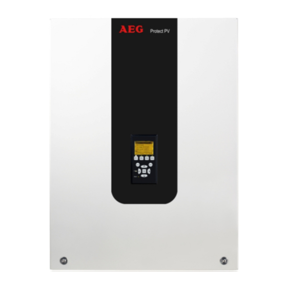
1. Introduction 1. Introduction 1.1. Introduction This manual provides information on functionality and maintenance of the Protect PV solar in- verter. Illustration 1.1: Protect PV 10 kW, Protect PV 12.5 kW, Protect PV 15 kW CE marking - This certifies the conformity of the equipment with the regula- tions which apply in accordance with the directives 2004/108/EC and 2006/95/EC. - Page 4 1. Introduction On grid (Green LED on) The inverter is connected to the grid and energises the grid. The inverter disconnects if: It de- tects abnormal grid conditions (depending on country settings), if an internal event occurs or if no PV power is available (no power is supplied to the grid for 10 minutes). It then goes into connecting mode or off grid mode.
-
Page 5: Display
The inverter is connected to a mas- ter. Icons can be found in the top right corner.* *) Protect PV easy only. Illustration 2.1: Display Note: The contrast level of the display can be altered by pressing the arrow up/down button while holding down the F1 button. -
Page 6: View
2. Display 2.1.1. View Menu Structure - View Parameter Description Mode: On grid Displays present inverter mode. See operation mode definitions Prod. today: 12345 kWh Energy production today in kWh. Value from inverter or S0 energy-meter Output Power: 12345 W Current output power in Watt [ --- utilization bar --- ] Shows level of inverter utilisation as % of max. -
Page 7: Status
[-] Reactive power Only displayed if the current country setting is an MV country or custom, and in Protect PV versions. The setpoint type for Reactive Power. Off means that no internal setpoints Setpoint type: Off are used, but the inverter will accept an external setpoint. - Page 8 2. Display Menu Structure - Status - Continued Display Functions Description [-] Inverter [-] Country: Germany Country setting [-] Internal Conditions Temperature detected at the power module Power module 1: 100 PCB1 (AUX): 100 Temperature detected internally [-] Serial no. and SW ver. [-] Inverter Prod- and serial number: A0010000201...
-
Page 9: Production Log
2. Display 2.1.4. Production Log Menu Structure - Production Log Display Functions Description Total production: Total production since installation of inverter 123456 kWh Total operating time: Total operating time since installation of inverter 20 hours [-] Production log [-] This week Production from this week Monday: 37 kWh Production from one day shown in KWh... - Page 10 Reactive Power: 0 h Due to reactive energy support [-] Reactive Power Only visible if the current country setting is an MV country or custom, and in Protect PV versions. [-] Reactive Energy (underexcited): 1000 000 VArh [-] Reactive Energy (overexcited):...
-
Page 11: Setup
The language in the display; changing the display language does Language: English not affect country setting [-] Inverter details Inverter name: AEG PS The inverter's name. Max. 15 characters and not only numbers. The name of the group the inverter is part of Group name: Group name Max. - Page 12 2. Display Menu Structure - Setup - Continued Display Functions Description GPRS connection setup SIM PIN code: 0000 4-8 characters Access point name: name Max. 24 characters User name: user Max. 24 characters Password: password Max. 24 characters Roaming: Disabled [-] Data warehouse service Upload channel: LAN Upload time (h:m): 14:55...
-
Page 13: Web Server Quick Guide
Setup Sequence: Select which inverter will be set up as master. Open the cover of this inverter. Refer to the Protect PV Installation Manual for instruc- tions. Connect the inverter RJ45 interface to the PC Ethernet interface using a patch cable (network cable cat5e, crossed or straight through). -
Page 14: Setup Wizard
3. Web Server Quick Guide Illustration 3.1: Product Label The Web Server logon dialog opens. Type 'admin' in the user and password fields, and click [Log in]. At initial logon the inverter runs a setup wizard. Ensure pop-ups are enabled before the wizard starts. - Page 15 Setup, Inverter details, Set Date and Time . To change these settings later, refer to Step 4 of 7: Installed power For each PV input, enter • surface area • installed power For more information refer to the Protect PV Reference Manual. 8000038784_00_BAL_en / L00410565-01_02...
- Page 16 3. Web Server Quick Guide Incorrect setting can have serious consequences for production efficiency. Illustration 3.5: Step 4 of 7: Installed Power Setup, Calibration, PV Array . To change the installed power, refer to Step 5 of 7: Country setting Select the country setting to match the installation.
- Page 17 3. Web Server Quick Guide Illustration 3.6: Step 5 of 7: Country Setting Note: If the initial and confirmation settings are different, • country selection is cancelled • the wizard recommences step 5 If initial and confirmation settings match, but are incorrect, contact service. Setup, Setup Details.
-
Page 18: Operation
3. Web Server Quick Guide Illustration 3.7: Step 6 of 7: Replication Step 7 of 7: Inverter startup The inverter will start automatically when the installation sequence is complete (see the Protect PV Installation Manual), and solar radiation is sufficient. The startup sequence, including self-test, takes a few minutes. - Page 19 3. Web Server Quick Guide Illustration 3.9: Overview Plant name: Displays the current plant name: • Click on the plant name to display the plant view. Change the plant name at [Setup → Plant details]. • Group menu: Displays groups of inverters: •...
-
Page 20: Plant, Group And Inverter Views
3. Web Server Quick Guide • Contact: Opens a pop-up window which displays AEG PS contact informa- tion. • Logout: Opens the log in / log out dialog box. • Security level: Displays the current security level as explained in the section Security Levels . -
Page 21: Additional Information
3. Web Server Quick Guide Item Unit View Description Plant Inverter Group Overall plant sta- Red: Plant PR <50%, or: Any inverter in the network - in fail safe mode, or - missing from the scan list, no contact with the master Yellow: Any inverter in the network - with PR<70%, or Connecting or Off grid mode... -
Page 22: Troubleshooting
AC and DC (PV) power. If the inverter re- sumes fail safe operation, action must be taken. Service inverter. Table 4.1: Events Note: For more event descriptions, refer to the Protect PV Reference Manual in the download area at: www.aegps.com/solarinverters 8000038784_00_BAL_en / L00410565-01_02... -
Page 23: Maintenance
5. Maintenance 5. Maintenance 5.1. Maintenance Normally, the inverter needs no maintenance or calibration. Ensure the heatsink at the rear of the inverter is not covered. Clean the contacts of the PV load switch once per year. Perform cleaning by cycling the switch to on and off positions ten times.The PV load switch is located at the base of the inverter. - Page 24 France & Africa Italy Czech Republic AEG Power Solutions AEG Power Solutions AEG Power Solutions spol. s r.o. ZI 10 rue Jean Perrin Via Trento 30 Na vlastní pude 6/1368 37173 Chambray-lès-Tours 20059 Vimercate – Milan 102 00 PRAHA 15 Hostivar...
Need help?
Do you have a question about the Protect PV and is the answer not in the manual?
Questions and answers