Table of Contents
Advertisement
Quick Links
Advertisement
Chapters
Table of Contents
Troubleshooting

Related Manuals for High End Systems Technobeam


Summary of Contents for High End Systems Technobeam
- Page 1 fi...
- Page 2 ADDR...
-
Page 4: User Manual
© High End Systems, Inc. 1998, All Rights Reserved Information and Specifications in this document are subject to change without notice. High End Systems, Inc. assumes no responsibility or liability for any errors or ® inaccuracies that may appear in this manual. The system software for the Status Cue lighting console described in this manual is furnished under a license agreement and may be used or copied only in accordance with the terms of the agreement. -
Page 5: Fcc Information
Patents Technobeam may use one or more of the following patents: US 4,962,687; US 5,078,039; UK 2,043,769; US 5,331,822; US 5,402,326; US D 372550; UK 2292896; US D365165; US 5,430,629;... -
Page 6: Declaration Of Conformity
IEC 801-4, 1988 Level 2 (1 kV/0.5 kV) U.S.A., September 1, 1999 Kenneth Stuart Hansen ® Technobeam User Manual Lightwave Research 2217 West Braker Lane Austin, Texas 78758 U.S.A. High End Systems Inc. 2217 West Braker Lane Austin, Texas 78758 U.S.A. Technobeam , Compliance Engineer... -
Page 7: Important Safety Information
Lea, por favor, todas las instrucciones antes del ensamblaje, montaje y operación de este equipo. Product Modification Warning High End Systems products are designed and manufactured to meet the requirements of United States and International safety regulations. Modifications to the product could affect safety and render the product non-compliant to relevant safety standards. -
Page 8: Warranty Information
Unless otherwise stated, your is covered by a two (2) year parts and labor limited warranty. The Laser Aiming Device (LAD™) for Technobeam is covered by a six (6) month ® parts and labor limited warranty. Dichroic filters and LithoPatterns high resolution glass gobos are not guaranteed against breakage or scratches to coating. - Page 9 Continental United States. REPAIR OR REPLACEMENT AS PROVIDED FOR UNDER THIS WARRANTY IS THE EXCLUSIVE REMEDY OF THE CONSUMER. HIGH END SYSTEMS, INC. MAKES NO WARRANTIES, EXPRESS OR IMPLIED, WITH RESPECT TO ANY PRODUCT, AND HIGH END SPECIFICALLY DISCLAIMS ANY WARRANTY OF MERCHANTABILITY OR FITNESS FOR A PARTICULAR PURPOSE.
-
Page 10: Table Of Contents
Table of Contents Introduction Features ...intro-1 Symbols ...intro-3 Document Conventions ...intro-3 Contacting High End Systems ...intro-4 Chapter 1 Preparing to Install Your Fixture Specifications ...1-2 Optional Accessories ...1-5 Unpacking the Fixture ...1-6 Installing the Power Cord Cap ...1-7 Installing the Yoke ...1-8 Setting the Fixture Voltage ... - Page 11 Replacing Fuses ...6-2 Replacing Wheel Components ...6-4 Replacing the Lamp ... 6-11 Cleaning the Internal Components ... 6-15 Technobeam Laser Aiming Device™ ... 6-19 Appendix A DMX Protocols General Information ... A-1 Technobeam® Protocol ... A-3 Technobeam-i™ Protocol ... A-7 MSpeed Movement Times ...
- Page 12 Figure 2-12. This fixture has software version 3..2-20 Figure 2-13. Location of the fixture’s exhaust vent..2-22 Figure 3-1. Technobeam navigation buttons..3-2 Figure 4-1. Making sure the shutter is open..4-5 Figure 4-2. A dot always appears in the LED display whenever preset playback is on.
- Page 13 ... 6-3 Figure 6-2. Locations of the three fuses on the circuit board... 6-4 Figure 6-3. Location of the wheels in Technobeam..6-5 Figure 6-4. Push the dichroic toward the large retaining tab to free it from the wheel tabs.
- Page 14 Figure 6-27. The laser aiming device assembly has three screws that can be used to adjust the position of the laser... 6-25 Figure B-1. Factory configuration of the Technobeam rotating litho wheel. . B-1 Figure B-2. Factory configuration of the Technobeam color wheel..B-2 Figure B-3.
- Page 15 ® Technobeam User Manual...
- Page 16 Introduction Features ...intro-1 Symbols ...intro-3 Document Conventions ...intro-3 Contacting High End Systems ...intro-4 Chapter 1 Preparing to Install Your Fixture Specifications ...1-2 Optional Accessories ...1-5 Unpacking the Fixture ...1-6 Installing the Power Cord Cap ...1-7 Installing the Yoke ...1-8 Setting the Fixture Voltage ... 1-10 Setting the Beam Angle ...
- Page 17 Replacing Fuses ...6-2 Replacing Wheel Components ...6-4 Replacing the Lamp ... 6-11 Cleaning the Internal Components ... 6-15 Technobeam Laser Aiming Device™ ... 6-19 Appendix A DMX Protocols General Information ... A-1 Technobeam® Protocol ... A-3 Technobeam-i™ Protocol ... A-7 MSpeed Movement Times ...
-
Page 18: Figure 1-4. The Three Voltage Selection Switches Located Next To The Led Display
Figure 6-1. Removing the door allows you to access the fixture’s voltage selection switches and fuses, as well as wheels and optics..6-3 Figure 6-2. Locations of the three fuses on the circuit board... 6-4 Figure 6-3. Location of the wheels in Technobeam..6-5 Ecodome User Manual... -
Page 19: Figure 6-9. The Gap Between The Two Halves Of The Rotating Litho Wheel Must Be Uniform
Figure 6-27. The laser aiming device assembly has three screws that can be used to adjust the position of the laser... 6-25 Figure B-1. Factory configuration of the Technobeam rotating litho wheel. . B-1 Figure B-2. Factory configuration of the Technobeam color wheel..B-2 Figure B-3. - Page 20 Ecodome User Manual...
- Page 21 Ecodome User Manual...
- Page 22 Table 3-1. Technobeam Menu Map ...3-3 Table 6-1. Replacement Fuses ...6-2 Table 6-2. Fuse Failure Symptoms ...6-3 Table A-1. Technobeam DMX Protocol ... A-3 Table A-2. Technobeam-i DMX Protocol ... A-8 Table A-3. MSpeed Movement Times ... A-13 Table A-4. Macro DMX Channel Assignments ... A-15 Table A-5.
- Page 23 Ecodome User Manual...
-
Page 24: Introduction
Technobeam has a factory-installed standard lens set with 11° to 17° beam angle, and an optional 8° to 12° narrow angle lens set. The fixture’s remote focus provides razor sharp beam or image projection at various trim heights and throw distances. - Page 25 Molded handles for easy transportation, lifting and mounting. Lamp High End Systems recommends you use an M series, GY9.5 base, 250- watt metal halide arc lamp (such as the MSD 250-2) which provides 6500K stable operation and extended lamp life.
-
Page 26: Symbols
Document Conventions Convention Meaning <key> Menu keys are indicated between braces. For example, the <Enter> key on the fixture’s key pad. BOLD BOLD type is used to indicate selections you make in the menu system. ® Technobeam User Manual Introduction Intro-3... -
Page 27: Contacting High End Systems
West Coast: High End Systems, Inc. 8200 Haskell Avenue Van Nuys, CA 91406 voice: (818) 947-0550 FAX: (818) 908-8975 High End Systems Singapore PTE. LTd. 1 Tannery Road 06-05 Cencon 1 Singapore 1334 voice: +65 742 8266 FAX: +65 743 9322... - Page 28 Model Numbers ...1-2 Dimensions (with yoke and handles) ...1-2 Weight (including yoke) ...1-2 Electrical Specifications ...1-2 Technobeam Laser Aiming Device™ (LAD™) ...1-2 LAD Safety Standards ...1-3 Important Power Cord Information - U.K. Only ...1-3 Vigtig Sikkerhedsinformation - DANMARK ...1-3 Dichroic, Litho and Effects Specifications ...1-4 Safety Standards ...1-4...
-
Page 29: Specifications
F3—250V, 6.3A, Slow Blow Only (5mm x 20mm) Class I equipment - This equipment must be earthed. Technobeam Laser Aiming ™ Device™ (LAD The specifications below apply only to Technobeam fixtures that have the Laser Aiming Device (LAD) installed. • Class 3a laser product •... -
Page 30: Lad Safety Standards
This equipment must be earthed. Vigtig Sikkerhedsinformation - DANMARK Advarsel: Beskyttelse mod elektrisk chock. Lederen med gul/groen isolation maa kun tilsluttes en klemme maerket ® Technobeam User Manual AVOID EXPOSURE Laser radiation is emitted from this aperture Emission indicator... -
Page 31: Dichroic, Litho And Effects Specifications
You can install any High End Systems-manufactured solid dichroic filters, effects LithoPatterns lithos, ArtGlass, or Fusion Fire as they were manufactured for use with Technobeam and not another fixture; otherwise, the dichroics, lithos or effects might not fit in the wheels properly. -
Page 32: Optional Accessories
• DMX data terminators: Male XLR connector with 120 ohm terminator between pins 2 and 3 (see Figure 2-4 on page 2-6) Controllers Technobeam may be controlled with any of the following: • The Status Cue • The Technobeam LCD controller •... -
Page 33: Unpacking The Fixture
Galvanized safety cable Lightwave Research Upload Dongle † - You must obtain the Laser Aiming Device from High End Systems Customer Service; see “Contacting High End Systems” on page Intro-4. Call - Contact either your High End Systems dealer/distributor, High End Systems Sales, or the High End Systems World Wide Web site. -
Page 34: Installing The Power Cord Cap
The type of power cord cap you must obtain depends on the location in which you will use Technobeam; different locations (even within the same country) might have different power cord cap requirements. -
Page 35: Vigtig Fikker Heds Information - Danmark
(1 on each side) Figure 1-1. Identifying yoke components. Installing the Yoke Vigtigt! eller one 1/4” allen wrench Yoke T-handle (1 on each side) Mounting holes (2 on each side) Side handle (loosen 2 allen screws to move yoke) ® Technobeam User Manual... -
Page 36: Figure 1-2. Installing The Yoke On The Fixture
Make sure the yoke is even (i.e., the same distance from the rear of the fixture on both sides). Securely tighten the four side handle allen screws (two on each side). Tilt the fixture to the desired angle, then securely tighten the other allen screws and T-handle. ® Technobeam User Manual Installing the Yoke... -
Page 37: Setting The Fixture Voltage
Setting the Fixture Voltage Technobeam is shipped from the factory set for 230V, 50Hz and offer the following switch-selectable voltage/frequency settings: 230 V, 50 Hz 100 V, 50 Hz 120 V, 50 Hz The recommended fuse F3 for all voltages and frequencies is: F3 - 250V, 6.3A, Slow Blow Only. -
Page 38: Figure 1-3. Removing The Door Allows You To Access The Fixture's Voltage Selection Switches, As Well As Wheels And Optics
Figure 1-5. Setting the fixture’s voltage and frequency. Replace the access door, unless you want to install the optional narrow lens set or set the beam angle as shown in the next section. ® Technobeam User Manual Door retaining screw Access door... -
Page 39: Setting The Beam Angle
Figure 1-7. Squeeze the two latches on each side of the lens tube to open the cover. 1-12 Setting the Beam Angle Lens tube Focus drive screw located under lens tube (turn drive screw to move lens tube for easier access) Technobeam ® User Manual... - Page 40 Use only a soft, lint-free cotton cloth to clean lenses. Use a mild glass cleaning solution if necessary to clean built- up dust or dirt. ® Technobeam User Manual Lens tube cover Arrow points to front of fixture Front lens...
-
Page 41: Table 1-3. Beam Angles For Optional 8 To 12 Degree Narrow Angle Lens Set
17.5° * - For the 11 to 17 degree lens set, the rear lenses must always be placed in slot 1 (see Figure 1-8 on page 1-13). Rear Lens Front Lens Position Position Technobeam Front Lens Position* ® User Manual... - Page 42 EMEM [message] ... 2-26 Erse Flsh ... 2-26 ID Lost ... 2-26 Lamp ... 2-27 Link Busy ... 2-27 Link Empty ... 2-27 Over Temp ... 2-28 PRST Lost ... 2-28 PGRM Time ... 2-28 Shut Down ... 2-28 ® Technobeam User Manual...
-
Page 43: Homing The Fixture
If the fixture fails to home, or if the menu displays an error message, see the section titled “Troubleshooting” on page 2-20 now. Powering On the Fixture MENU ENTER ® Technobeam User Manual... -
Page 44: Figure 2-2. Location Of The Three Status Leds On The Fixture's Access Door
Status LEDs Technobeam fixtures have three status LEDs located on the access door, as shown in Figure 2-2: Figure 2-2. Location of the three status LEDs on the fixture’s access door. Table 2-1 describes the three status LEDs: LED name... -
Page 45: Overview Of Controller Operation
4-9. Try unplugging the fixture, waiting a few minutes, then plugging it back in. If the Transmit LED continues to be ON, contact High End Systems Customer Service in one of the ways shown in the section titled “Contacting High End Systems” on page Intro-4. -
Page 46: Constructing Cabling
For example, Belden EIA RS-485 applications and is highly recommended (or its equivalent) for use with Technobeam. Constructing Cabling If you need to construct cabling, you must use a shielded, two- conductor cable with a male 3-pin XLR connector on one end and a female 3-pin XLR connector on the other end. -
Page 47: Figure 2-4. Constructing A Data Cable Terminator
® and Emulator laser simulators will stop software uploads to Technobeam fixtures farther down the link. Make sure you put all of the Intellabeam fixtures, Emulator fixtures and AF1000 fixtures after all of the Technobeam fixtures. As long as you observe all of the rules above, you can use whatever DMX channels and cabling scheme you want. -
Page 48: Linking The Fixtures To The Controller
Data In connector to the next fixture until you have linked all of the Technobeam fixtures. Connect other devices to the Technobeam fixtures as desired, using the instructions in the documentation provided with those devices. Place a male 120 ohm terminator on the female Data Out connector of the last device in the link. -
Page 49: Mounting The Fixture
20 A. (2) Class I Equipment - This fixture must be earthed. Mounting the Fixture Data In Data Out Data In Data Out Terminate the l t fi t Technobeam Data In Data Out Data In ® User Manual... -
Page 50: Standing The Fixture On Its End Handles
Verify the truss or support will handle the weight of all the devices you are mounting. Technobeam fixture weights are listed in the section titled “Weight (including yoke)” on page 1-2. The use of user-supplied safety cable is strongly recommended. You... -
Page 51: Figure 2-7. Use A Locking Washer When Attaching A Fixture To A Truss
High End Systems dealer/distributor (part number 55000004). Also see the section titled “Optional Accessories” on page 1-5. Make sure the fixture cannot be rotated all the way around (360 Allowing the fixture to rotate 360 bolts. Note Because of the variety of conceivable lighting designs, you should consider the procedure below as a suggested guideline only. -
Page 52: Figure 2-8. Always Use A Safety Cable When Mounting The Fixture
Tighten the T-handles to secure the fixture in the desired position. When you have the fixture in the position you want, firmly tighten the T-handles shown in Figure 2-9. Figure 2-9. Location of the T-handle you use to adjust the yoke position. ® Technobeam User Manual MODEL TECHN OBEAM 29FA000000... -
Page 53: Figure 2-10. You Can Slide The Yoke All The Way Back To Allow The Fixture To Hang Upside-Down
Hanging the Fixture Straight Down You can mount Technobeam with the mirror head perpendicular to the ground for projection onto a stage. This orientation also allows you to economize truss space by hanging fixtures side by side close to each other. -
Page 54: Configuring The Fixture
• TB F - Technobeam full protocol - uses 18 DMX channels per fixture. The full protocol gives you more control over pan and tilt position and litho spin speed and is for use with fixtures that do not have an iris. -
Page 55: Selecting A Control Method
Using the <Up> and <Down> arrow buttons, scroll to the “DMX” option and press the <Enter> button to select the “DMX” option. Note You must select a control method for each Technobeam fixture on the link. Fixture Number Control Method When you use the fixture number control method, each fixture “thinks”... -
Page 56: Assigning A Fixture Address
The size of each fixture’s channel range is determined by the fixture type (see “Fixture Types” on page 2-13). Each Technobeam set to full, iris, or LCD protocol reserves a block of 18 contiguous channels. Each Technobeam set to reduced protocol reserves a block of 14 contiguous channels. -
Page 57: Table 2-2. Example: Determining The Dmx Start Channel
DMX channels used by the fixture to the fixture’s DMX start channel. For example, in Table 2-2, 18 (channels used by the Technobeam set to iris protocol) + 1 (DMX start channel for the first fixture) = 19 (DMX start channel for the next fixture on the link). -
Page 58: Table 2-3. Example: Determining The Unique Fixture Number
<Enter> button. Note You must assign a unique fixture address to each Technobeam fixture that you wish to respond independently to controller commands. Wasted DMX Channels If you mix different types of devices (which use different numbers of... -
Page 59: Upgrading Software
15 as the first channel in its channel range. This would create channel overlapping because fixture number 1 (Technobeam iris protocol) is already using channel 15 in its 18- channel range. In this example, to prevent overlapping channels, you must assign fixture number 3 (F 03) to the Technobeam (reduced protocol), even though it is physically the second fixture on the DMX link. -
Page 60: Figure 2-12. This Fixture Has Software Version 3
If there are any Dataflash AF1000 xenon strobe fixtures, Emulator laser simulators or Intellabeam automated luminaires on the same link, make sure they are all after all of the Technobeam fixtures. If not, you must bypass all AF1000s, Emulators or Intellabeams until the upload is complete. -
Page 61: Troubleshooting
ON (or flicker) during the crossload. The Transmit and Receive LEDs on other Technobeam fixtures on the link will flicker while the crossload is in progress. When the crossload has finished successfully, the following will happen: •... -
Page 62: Figure 2-13. Location Of The Fixture's Exhaust Vent
Figure 2-13. You should feel a slight breeze from the fan. If not, the fan has failed. Contact High End Systems Customer Service as shown in “Contacting High End Systems” on page Intro-4. - Page 63 Color wheel or litho wheel is not centered in the beam or is in the wrong position Cause: Non-High End Systems dichroic or litho does not meet specifications. A litho that is slightly under the recommended thickness, for example, can turn in the wheel as the wheel rotates, causing the litho to become uncentered.
- Page 64 Figure 2-13 on page 2-21. You should feel air movement. If not, the fan has failed. Contact High End Systems Customer Service as shown in “Contacting High End Systems” on page Intro-4.
-
Page 65: Troubleshooting Dmx Data
Troubleshooting DMX Data This section explains how to use the DMX diagnostics built into Technobeam to isolate the origin of data problems either in the fixture or in the DMX 512 link. The instructions in this section should be followed only by people with a good understanding of DMX 512 protocol and the fixture’s menu system. -
Page 66: Menu Error Messages
LED display, as well as suggested actions. If the suggested action does not solve the problem or if you have additional questions, contact High End Systems Customer Service in one of the ways shown in the section titled “Contacting High End Systems” on page Intro-4. -
Page 67: Emem Ack
This error may occur during data storage when an attempted write has taken too long. Attempt the operation again. If this message reoccurs, contact High End Systems Customer Service in one of the ways shown in the section titled “Contacting High End Systems” on page Intro-4. -
Page 68: Lamp
Link Empty Occurs when the crossloading fixture fails to find any other Technobeam fixtures. If there are indeed other fixtures on the link, a communication failure has occurred. Possible causes include: A bad data cable between the crossloading fixture and the first fixture on the data link. -
Page 69: Over Temp
“Setting the Fixture Voltage” on page 1-10. If the voltage setting is correct, contact High End Systems Customer Service in one of the ways shown in the section titled “Contacting High End Systems” on page Intro-4. - Page 70 Setting Preset Playback (PLAY) ... 3-28 Editing or Creating an On-Board Memory Scene (EDIT) ... 3-29 Copying an On-Board Memory Scene (COPY) ... 3-29 Capturing a Preset Scene (CAPT) ... 3-29 Enabling the Preset Default (DFLT) ... 3-30 ® Technobeam User Manual...
-
Page 71: Menu System Overview
Menu System Overview The Technobeam menu system allows you to: • Configure your fixture for operation (discussed in Chapter 2) • Access fixture options such as homing the fixture, crossloading software, and performing self tests (discussed in this chapter) •... -
Page 72: Menu Map
Menu Map A complete menu map and explanations of the Technobeam menu options are listed in this section. See individual subsections in this addendum for descriptions of each menu item. Chapter 4 has more information about using the menus to program the fixture’s sixteen onboard scenes (presets). - Page 73 F/HR L/ST Menu Map Menu Menu Level 4 Level 5 Technobeam full protocol (uses 18 channels) Technobeam reduced protocol (uses 14 channels) Technoray full protocol (uses 14 channels) Technoray reduced protocol (uses 12 channels) Technopro protocol (uses 12 channels) Technobeam-i (uses 18 channels)
- Page 74 Table 3-1. Technobeam Menu Map Menu Menu Menu Level 1 Level 2 Level 3 FIXT FIXT INFO DATA SENS COLR F/RS L/RS UNUM PRST PLAY ® Technobeam User Manual Menu Menu Level 4 Level 5 view the number of framing errors with zero...
- Page 75 Table 3-1. Technobeam Menu Map Menu Menu Menu Level 1 Level 2 Level 3 SN01 - PRST EDIT SN16 Menu Map Menu Menu Level 4 Level 5 CLSD shutter closed P 01 - periodic shutter strobe at specified intervals, P 60...
- Page 76 Table 3-1. Technobeam Menu Map Menu Menu Menu Level 1 Level 2 Level 3 SN01- PRST EDIT SN16 ® Technobeam User Manual Menu Menu Level 4 Level 5 select a reverse color wheel spin speed from R000 - none (R000) to fast (R255) (only available if...
- Page 77 Table 3-1. Technobeam Menu Map Menu Menu Menu Level 1 Level 2 Level 3 SN01- PRST EDIT SN16 Menu Map Menu Menu Level 4 Level 5 select a reverse spinning litho position (only LR 1 - available if you selected a LTOC construct...
- Page 78 Table 3-1. Technobeam Menu Map Menu Menu Menu Level 1 Level 2 Level 3 SN01- PRST EDIT SN16 ® Technobeam User Manual Menu Menu Level 4 Level 5 OPEN fully open the iris P 01 - select a speed to strobe the beam diameter,...
-
Page 79: Menu Options
The LED display will stop flashing when a new option is entered. If you do not press the <Enter> button, the new option you selected will not be stored. Note 3-10 Menu Options Table 3-1. Technobeam Menu Map Menu Menu Level 4 Level 5 FA01 -... -
Page 80: Set Menu (Set)
The procedures below are listed in the order that they appear in the menu map. Setting Factory Defaults (FACT) Technobeam-i fixtures are shipped from the factory with the following preset options set to the following defaults: • Pan/tilt swap = off •... -
Page 81: Swapping Pan And Tilt (Swap)
Using the <Up> and <Down> arrow buttons, choose the “ON” option to invert the fixture’s pan motion, or the “OFF” option to return the fixture’s pan motion to normal orientation. Press the <Enter> button to select the desired option. 3-12 Menu Options ® Technobeam User Manual... -
Page 82: Changing The Display Output (Dspl)
To simply change an existing fixture number to a different fixture number (or DMX start channel to a different DMX start channel), see “Address Menu (ADDR)” on page 3-10. ® Technobeam User Manual Menu Options 3-13... -
Page 83: Setting The Lamp Warning Message (Lmpl)
Changing the Lens Setting (LENS) Use this menu item if you change the lenses in your fixture. Available lens sets include standard, narrow angle, and wide angle lenses. To obtain a different lens set, contact your High End Systems dealer/ distributor. 3-14... -
Page 84: Mode Menu (Mode)
Mode Menu (MODE) The Mode menu allows you to set the fixture type and protocol and crossload software versions from one fixture to all other Technobeam-i fixtures on the link. The procedures below are listed in the order that they appear on the menu map. -
Page 85: Setting The User Type (User)
TPRO (Technopro protocol) - for use with Technopro fixtures only. This protocol uses 12 DMX channels. • (Technobeam-i protocol) - for use with Technobeam-i TB I fixtures (fixtures with an iris). This protocol uses 18 DMX channels and allows you to access the Laser Aiming Device™... -
Page 86: Copying User Presets (Prst)
Using the <Up> and <Down> arrow buttons, scroll to the “PRST” menu and press the <Enter> button to select the “PRST” menu. ® Technobeam User Manual This options copies all 16 presets at one time. To copy an individual scene, see “Copying an On-Board Memory Scene (COPY)”... -
Page 87: Copying User Settings (Sett)
This options copies all user settings at one time. This options copies all user settings and all 16 presets at one time. ” option ” option to copy user B B” option A” option to copy user B ® Technobeam User Manual... -
Page 88: Crossloading Fixture Software (Xld)
B presets and settings to user A. Press the <Enter> button to select the desired option. Crossloading Fixture Software (XLD) If you have a Technobeam-i fixture with a newer software version, you can crossload the newer software to all other Technobeam-i fixtures on the link. -
Page 89: Test Menu (Test)
Using the <Up> and <Down> arrow buttons, scroll to the “LAMP” menu and press the <Enter> button to select the “LAMP” menu. Using the <Up> and <Down> arrow buttons, choose the “ON” option to strike the lamp, the “OFF” option to extinguish the lamp. 3-20 Menu Options ® Technobeam User Manual... -
Page 90: Copying The Boot Code (Boot)
Copying the Boot Code (BOOT) When you upload new software to Technobeam-i fixtures, the new software may contain a new boot code which must be copied to each fixture. This is apparent if the LED displays a “BOOT DIFF” error. Do not remove power from the fixture while performing a boot copy. -
Page 91: Placing The Fixture In Setup Mode (S/Up)
DMX errors, sensor information, and DMX data for any other device on the link. You can also reset the lamp 3-22 Menu Options ® Technobeam User Manual... -
Page 92: Viewing The Logic Board Temperature (Temp)
Using the <Up> and <Down> arrow buttons, scroll to the “F/HR” option and press the <Enter> button to select the “F/HR” option. The LED will display the number of hours the fixture has been on since this option was reset. ® Technobeam User Manual Menu Options 3-23... -
Page 93: Viewing The Number Of Current Lamp Strikes (L/St)
BRKS - number of DMX breaks (framing errors with zero data) • FE - number of framing errors with a non-zero value (errors in data transmission) • OV - overruns (changing values could indicate data link/connector problems) • STRT - start code 3-24 Menu Options ® Technobeam User Manual... - Page 94 LAD - Laser Aiming Device* • CNTL - control channel *Note If your Technobeam-i does not have an iris and/or Laser Aiming Device (LAD), the iris and LAD-related constructs will have no functionality. To view the DMX status and construct values: Press and hold the <Menu>...
-
Page 95: Viewing Dmx Data For Another Device (Data)
High End Systems customer service. Viewing DMX Data for Another Device (DATA) This procedure allows you to use an Technobeam-i fixture to view DMX channel values for other devices on the DMX link. You should use this procedure either for testing devices that do not have built-in DMX diagnostics, or for fixtures that are physically inconvenient to monitor directly. -
Page 96: Resetting Fixture Hours (F/Rs)
<Enter> button for at least 5 seconds. Resetting Lamp Hours (L/RS) This menu item allows you to track the number of hours the lamp has been operating. You should reset the lamp hours every time you change the lamp. ® Technobeam User Manual Menu Options 3-27... -
Page 97: Preset Menu (Prst)
“OFF” option to set preset playback off, or the “SCN” option to display which scene is currently playing. Press the <Enter> button to select the desired option. Note Scene 1 must be programmed before the fixture can play back scenes. 3-28 Menu Options ® Technobeam User Manual... -
Page 98: Editing Or Creating An On-Board Memory Scene (Edit)
When the fixture finishes the copy successfully, “DONE” will appear briefly in the fixture’s LED display. Capturing a Preset Scene (CAPT) Preset capturing is a way to automate the creation of scenes on multiple Technobeam-i fixtures connected to a DMX 512 link. Use a ® Technobeam User Manual... -
Page 99: Enabling The Preset Default (Dflt)
DMX controller will not transmit those construct values. For more information on using the fixture’s on-board scene memory, refer to the ® Technobeam User Manual. To play the fixture’s self-demo, you must set preset playback on (see “Setting Preset Playback (PLAY)” on page 3-28). - Page 100 Selecting Effects Constructs ...4-7 Refocusing the Fixture ...4-7 Setting a Delay Time ...4-7 Creating Scene 2 ...4-8 Playing Back Both Scenes ...4-8 Synchronizing Preset Playback ...4-9 Setting Up the Fixtures ...4-9 Adding Fixtures ... 4-11 Capturing Presets ... 4-11 ® Technobeam User Manual...
-
Page 101: Programming Overview
(using preset programming) enter values for these two constructs. Macros Each Technobeam fixture has 28 selectable macros. A macro is a factory-programmed set of fixture constructs picked for their ability to achieve a dramatic and exciting effect. Using a macro can help you save time while programming your fixture. -
Page 102: Preset Playback Options
Preset Playback Options Technobeam offers the following two options for use with preset programming: • Preset capture: Use any DMX 512-compatible controller to create a scene(s) that can then be saved into the fixture’s own presets and later recalled in stand-alone operation without the controller. The only constructs that cannot be captured in this way are crossfade (XFAD) and delay (DLAY);... -
Page 103: Creating A Scene
Orient (physically position) the fixture so the light will be projected onto a flat, light-colored object such as a white wall or ceiling. If you have Technobeam, you will be able to move the mirror to a suitable position. Follow the instructions in Chapter 1 to connect the fixture to an appropriately-rated power outlet, if you have not already done so. -
Page 104: Figure 4-1. Making Sure The Shutter Is Open
Figure 4-1. (The two dim flags act as both the dimming mechanism and as the shutter.) Aperture (dim flags are barely visible at edges when shutter is open) Figure 4-1. Making sure the shutter is open. ® Technobeam User Manual Creating a Scene... -
Page 105: Positioning The Mirror
Press <Enter>, then press the <Up> and <Down> arrow keys to select RND (random color selection). Press <Enter>. The color wheel spins and stops on a random position, pausing for a length of time you will set in the next section. Creating a Scene ® Technobeam User Manual... -
Page 106: Selecting A Color Wheel Pause Time
3.0. This means that scene 1 will “play” for 3 seconds before moving on to scene 2. (You will not see the effect of the DLAY construct until you play back your programmed scenes.) ® Technobeam User Manual Creating a Scene... -
Page 107: Creating Scene 2
12. Press <Enter> and change the DLAY construct to a value of 1.0. 13. Press <Enter> to accept your selection. Make other construct changes, if desired (if you have Technobeam, move the mirror to a different location using the PAN and TILT constructs.) -
Page 108: Synchronizing Preset Playback
(with no scene active). Synchronizing Preset Playback Once you have programmed one or more scenes for your Technobeam fixtures and connected them to a DMX 512 link, you can synchronize preset playback from one fixture as described in this section. -
Page 109: Number 1 Or Dmx Start Channel 1. The Last Fixture On The Link Must Be Terminated
1. The last fixture on the link must be terminated. 4-10 Synchronizing Preset Playback Data In Data Out Data In Terminate the last fixture (the fixture at the opposite end of the link from the first fixture) Technobeam ® User Manual... -
Page 110: Capturing Presets
Capturing Presets Preset capturing is a way to automate the creation of scenes on multiple Technobeam fixtures connected to a DMX 512 link. You use a DMX 512-compatible controller to create a scene, save (capture) the scene into a fixture's presets and later play back the scene without the controller. - Page 111 (To make the scene active, select the scene number from the EDIT menu.) 11. Repeat the procedure for each fixture you want to capture presets to. 4-12 Capturing Presets ® Technobeam User Manual...
- Page 112 Troubleshooting ...5-6 Laser gradually loses power ...5-6 Laser is out of position ...5-6 Emission Indicator LED OFF, Laser OFF ...5-6 Emission Indicator LED ON, Laser OFF ...5-7 Laser ON, Emission Indicator LED OFF ...5-8 Maintenance ...5-8 ® Technobeam User Manual...
-
Page 113: Safety Precautions
Using the Laser Aiming Device with any fixture other than Technobeam may result in damage to both the laser and the fixture as well as exposure to laser radiation. -
Page 114: Overview
“Controlling the Laser” on page 5-5. The laser exits the fixture through the same aperture as the light beam, as shown in Figure 5-1. Technobeam was designed so that the laser is visible if the dim flags are completely closed or open. -
Page 115: Figure 5-2. The Ideal Position Of The Laser Is No More Than 2" (5 Cm) Directly Above The Center Point Of A Perfectly Round Light Beam
If the laser becomes out of position, you might need to align it as shown in the section titled “Technobeam Laser Aiming Device™” on page 6-19. However, the decision of whether or not to align the laser is entirely up to you. -
Page 116: Controlling The Laser
Select a fixture number or DMX start channel for each fixture you wish to control as described in Chapter 2. Make sure you select the Technobeam full 18-channel protocol (TB F from the Mode menu); otherwise, the laser aiming device will not function. -
Page 117: Troubleshooting
Systems Customer Service in one of the ways shown in “Contacting High End Systems” on page Intro-4. Laser is out of position Align the laser as shown in the section titled “Technobeam Laser Aiming Device™” on page 6-19. Emission Indicator LED OFF, Laser OFF The laser circuit board is not receiving power. -
Page 118: Figure 5-4. Lad Wiring Connections
If the Emission Indicator LED and laser are both still OFF, contact High End Systems Customer Service in one of the ways shown in “Contacting High End Systems” on page Intro-4. Emission Indicator LED ON, Laser OFF The laser aiming device assembly is not receiving power. Check the connection at the laser aiming device circuit board, shown in Figure 5-5. -
Page 119: Maintenance
Figure 5-5. The laser aiming device circuit board. If the cable connections are good, contact High End Systems Customer Service in one of the ways shown in “Contacting High End Systems” on page Intro-4. Laser ON, Emission Indicator LED OFF The most likely reason is a faulty Emission Indicator LED. - Page 120 Cleaning the Internal Components ... 6-15 Opening the Fixture ... 6-16 Cleaning the Door Vents ... 6-16 Cleaning the Lenses and Mirrors ... 6-16 Technobeam Laser Aiming Device™ ... 6-19 Safety Precautions ... 6-19 Live Components ... 6-20 Alignment Procedure ... 6-21 ®...
-
Page 121: Precautions
(5) Never look directly at the lamp while lamp is on. (6) The procedures in this chapter are intended to assist qualified service personnel because Technobeam fixtures are to be serviced by qualified service personnel only. Replacing Fuses This section explains how to replace any of the three fuses located on the fixture’s circuit board. -
Page 122: Figure 6-1. Removing The Door Allows You To Access The Fixture's Voltage Selection Switches And Fuses, As Well As Wheels And Optics
Note which fuse(s) needs to be replaced and make sure you replace it with a fuse of the same type and rating, as shown in Table 6-2. ® Technobeam User Manual Symptoms of Failure Door retaining screw... -
Page 123: Replacing Wheel Components
You can install any High End Systems-manufactured solid dichroic filters, effects, LithoPatterns lithos, ArtGlass, or Fusion Fire as they were manufactured for use with Technobeam, Technopro or Technoray and not another fixture. You can also install dichroics, gobos, lithos or effects from other... -
Page 124: Figure 6-3. Location Of The Wheels In Technobeam
0.25 mm) • Maximum thickness: 0.175” ± 0.010” (4.4 mm ± 0.25 mm) Reference Drawing Figure 6-3 shows the location of each wheel in the Technobeam fixture. Color wheel Rotating litho wheel Rotating effects wheel Figure 6-3. Location of the wheels in Technobeam. -
Page 125: The Reflection From The Object Will Appear To Touch The Object
Figure 6-5. You can easily tell which side of a dichroic is coated by placing a pen or other object near the surface; on the coated side, the reflection from the object will appear to touch the object. Replacing Wheel Components coated uncoated Technobeam ® User Manual... -
Page 126: Figure 6-6. The Rotating Litho Wheel And Rotating Effects Wheel Have Built-In Plastic Tabs That Hold The Spring In Place
Replacing Lithos in the Rotating Litho Wheel This section explains how to replace either of the two lithos in each position on the Technobeam or Technoray rotating litho wheel: the rotating litho (facing the rotating effects wheel) and the static litho (directly behind the rotating litho). -
Page 127: Figure 6-7. To Replace A Static Litho In The Rotating Litho Wheel, Gently Separate The Wheel And Reach Behind The Wheel To Push The Litho Out
Cleaning the Litho Clean the litho, if necessary, using a mild glass cleaner (containing no ammonia) and a soft, lint-free cotton cloth. Replacing Wheel Components Aperture Litho ring Pull litho out Gently separate wheel ® Technobeam User Manual... -
Page 128: Figure 6-8. Location Of The Retaining Tabs And Slot That Secure The Static Litho In The Rotating Litho Wheel
If the gap is not uniform, continue seating the static litho until the gap is uniform. Figure 6-9. The gap between the two halves of the rotating litho wheel must be uniform. ® Technobeam User Manual Replacing Wheel Components... -
Page 129: Sure The Tip Of The Spring Is Fully Seated Under The Wheel Tabs; It Cannot Protrude From Under The Tabs
You are finished. Replace the access door shown in Figure 6-1 on page 6-3 unless there are other dichroics, lithos or effects you want to replace. 6-10 Replacing Wheel Components Litho Aperture Spring (first) ring (next) (last) Technobeam Wheel tab Incorrect placement (spring tip protrudes from under tab) ® User Manual... -
Page 130: Replacing The Lamp
– Eye protection – Protective gloves *Note Use only the MSD250-2 lamp in your fixture, not the MSD 250. Technobeam fixtures are optimized for the MSD 250-2 lamp and will give reduced performance with other lamps. WARNINGS (1) This equipment is designed for use with an M series, GY9.5 base, 250 watt (such as the... -
Page 131: Figure 6-13. Loosening The Lamp Assembly Screws Gives You Access To The Fixture Lamp
Put on your eye and hand protection. Pull the lamp assembly straight out of the back of the fixture as shown in Figure 6-14. Figure 6-14. Removing the lamp assembly from the fixture. 6-12 Replacing the Lamp ® Technobeam User Manual... -
Page 132: Figure 6-15. Pull Straight Up On The Lamp, Grasping Its Ceramic Base, To Remove It From The Assembly
Carefully guide the lamp assembly straight back into the fixture. Make sure the lamp plate is oriented correctly, as shown in Figure 6-17; otherwise, the lamp power wires could wrap around the lamp, resulting in damage to the fixture and the lamp. ® Technobeam User Manual Replacing the Lamp 6-13... -
Page 133: Plate Is Oriented Correctly; Incorrect Orientation Can Result In Damage To The Fixture And The Lamp
(see “Positioning the Mirror” on page 4-6). Adjust the focus until the edge of the light beam is sharp (see “Refocusing the Fixture” on page 4-7). 6-14 Replacing the Lamp ® Technobeam User Manual... -
Page 134: Cleaning The Internal Components
Before continuing, read the cautions and warnings in the section titled “Precautions” on page 6-2. You will need: - a soft, lint-free cotton cloth - mild glass cleaning solution - warm soapy water ® Technobeam User Manual Cleaning the Internal Components 6-15... -
Page 135: Figure 6-19. Opening The Fixture's Access Door
(see Figure 6-20). Clean both sides of the anti-reflective glass (shown in Figure 6-20) with a soft, lint-free cotton cloth and mild glass cleaning solution. 6-16 Cleaning the Internal Components Door retaining screw Access door ® Technobeam User Manual... -
Page 136: Figure 6-20. Location Of The Anti-Reflective Glass, Lenses And Hot Mirror
Figure 6-21. The lens tube contains the zoom lenses. Carefully lift the cover from the lens tube. It has two latches on each side that secure it in place. ® Technobeam User Manual Lens tube Cleaning the Internal Components Anti-reflective glass... -
Page 137: Figure 6-22. Clean Both Sides Of The Hot Mirror Glass
Phillips screw. 15. Technobeam only: Clean the elliptical mirror on the mirror head with a cloth soaked in warm, soapy water. -
Page 138: Technobeam Laser Aiming Device
Using the Laser Aiming Device with any fixture other than Technobeam may result in damage to both the laser and the fixture as well as exposure to laser radiation. -
Page 139: Figure 6-24. High-Voltage Component Location
Figure 6-24. High-voltage component location. When you activate the laser, observe the following precaution: Caution Do not stare into the beam or view it directly with optical instruments. Avoid accidental exposure to laser radiation. 6-20 Technobeam Laser Aiming Device™ ® Technobeam User Manual... -
Page 140: Figure 6-25. Orient The Fixture Directly Facing A Wall No Less Than 10 Ft
Alignment Procedure The alignment procedure that follows takes advantage of Technobeam’s built-in program storage capability to turn the laser ON. Follow the instructions in Chapter 1 to select a voltage setting and install a power cord cap, if you have not already done so. - Page 141 • If the beam is round (not oval) in shape, continue with Step 31. • If the beam is not round in shape, see the next step. 6-22 Technobeam Laser Aiming Device™ ® Technobeam User Manual...
- Page 142 33. Continue moving the fixture and focusing on the edge of the beam until the beam is as round as possible, and sharply in focus. 34. When you have focused the beam, press <Enter>. ® Technobeam User Manual Technobeam Laser Aiming Device™ 6-23...
-
Page 143: Figure 6-26. Locating The Center Point Of The Projected Light Beam. The Laser Should Be No More Than 2" (5 Cm) Above The Center
Caution Do not stare into the laser beam or view it directly with optical instruments. 6-24 Technobeam Laser Aiming Device™ Line you made in Step 2 Ideal laser spot Extend the string across the beam's widest point. Laser should be no more than 2"... -
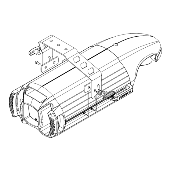
Page 144: Figure 6-27. The Laser Aiming Device Assembly Has Three Screws That Can Be Used To Adjust The Position Of The Laser
6-19, but it is still at a position you think will give you enough accuracy for your needs, you are finished.) 53. When you’re finished, replace the access door shown in Figure 6-19 on page 6-16. ® Technobeam User Manual Mounting/alignment screws Technobeam Laser Aiming Device™ 6-25... - Page 145 ® 6-26 Technobeam Laser Aiming Device™ Technobeam User Manual...
-
Page 146: Appendix Admx Protocols
16-Bit Control The full protocol for Technobeam gives you 16-bit control over the positioning of the mirror and the angular position of rotating lithos. However, you always have smooth, 16-bit control over movement, even if you choose the reduced protocol—which gives you 8-bit control over mirror and litho positioning. -
Page 147: Mspeed Vs. Fast Changes
Forward and Reverse Spins A forward spin on all wheels and positions means the wheel or position spins clockwise as you’re looking at the projected image. A reverse spin means the wheel or position spins counter-clockwise. DMX Protocols ® Technobeam User Manual... -
Page 148: Technobeam® Protocol
Technobeam Table A-1 gives the DMX channel assignments for the Technobeam full 18- channel protocol and reduced 14-channel protocol. The column “Ch. (F)” lists channel assignments for the full protocol and the column “Ch. (R)” lists channel assignments for the reduced protocol. - Page 149 Table A-1. Technobeam DMX Protocol Ch. (F) Ch. (R) Construct Color wheel continuous forward/ reverse spin (use with ch. 5 (F) or 3 (R)) Color wheel continuous variation (wheel position is 360 * (channel dec. value / 255) Use with ch. 5 (F) or 3 (R)
- Page 150 Table A-1. Technobeam DMX Protocol Ch. (F) Ch. (R) Construct Litho wheel functions Fast litho changes (at beginning of wheel movement) Select the function with this channel. Then use chs. 8, 9 & 10 (F) or chs. 6 & 7 (R) to set other options.
- Page 151 Table A-1. Technobeam DMX Protocol Ch. (F) Ch. (R) Construct Random Scan Litho wheel spin (use with ch. 7 (F) or ch. 5 (R) Entire wheel spins, not individual lithos Litho rotation (fine adjustment) Effects position Fast effects changes (at...
-
Page 152: Technobeam-I™ Protocol
Technobeam-i™ Protocol Table 2 lists the 18 Technobeam-i constructs and their corresponding DMX controller values. If you have a numeric-type controller, use the Value Decimal (dec.) column. If you have a fader-type controller, use the Value Percentage (%) column. If your controller allows you to program hex values, use the Value (hex) column. -
Page 153: Table A-2. Technobeam-I Dmx Protocol
Table A-2. Technobeam-i DMX Protocol Construct Pan (mirror) Coarse adjustment (8-bit) position Pan (mirror) Fine adjustment (8-bit) position Tilt (mirror) position Coarse adjustment (8-bit) Tilt (mirror) position Fine adjustment (8-bit) Color Function Full Speed Control Indexed Forward Spin Reverse Spin... - Page 154 Table A-2. Technobeam-i DMX Protocol Construct Color Wheel Colors 10 and 11 (cont.) Position (cont.) Colors 11 and 12 Colors 12 and 13 Colors 13 and 1 Color 1 Continuously Variable Forward Spin Mode Spin Stop Spin Forward Slowest Spin Forward Fastest...
- Page 155 Table A-2. Technobeam-i DMX Protocol Construct Color Wheel Color 7 and 8 and 9 (cont.) Position (cont.) Color 8 and 9 and 10 Color 9 and 10 and 11 Color 10 and 11 and 12 Color 11 and 12 and 13...
- Page 156 Table A-2. Technobeam-i DMX Protocol Construct Iris Close Variable Iris Open Periodic Strobe Random Strobe Ramp Open/Snap Shut Snap Open/Ramp Shut Ramp Open/Ramp Shut Random Ramp Open/Snap Shut Random Snap Open/Ramp Shut Open Effects Wheel Full Speed Control Position Effect 1...
-
Page 157: Mspeed Movement Times
MSpeed Movement Times Use Table A-3 to determine the MSpeed (motor/mirror) movement times for Technobeam, Technopro or Technoray in seconds. An MSpeed (motor/mirror speed) change occurs smoothly over the entire MSpeed time value. For example, if you choose a numerical DMX value of 202 for an MSpeed color change from position 2 to position 4, that means the color wheel changes gradually to position 4 over 11.41 seconds. -
Page 158: Table A-3. Mspeed Movement Times
2.86 3.07 3.29 3.52 3.76 4.00 4.25 4.52 4.78 5.06 5.34 5.64 5.94 6.25 6.56 6.89 7.22 7.56 ® Technobeam User Manual Time Value Value Value (sec.) (dec.) (hex) 7.91 8.27 8.63 9.00 9.39 9.77 10.17 10.58 10.99 11.41 11.84 12.28... - Page 159 197.70 199.48 201.28 203.08 204.88 206.70 208.52 210.36 212.19 214.04 215.90 217.76 219.63 221.51 223.40 225.30 227.20 229.11 231.03 232.96 234.90 236.84 238.79 240.75 242.72 244.70 246.68 248.68 250.68 252.68 0.19 0.19 0.19 0.19 ® Technobeam User Manual Value (hex)
-
Page 160: Macro Channel Assignments
You do not have to use macros in your scene, but using them can save you programming time. Use DMX channel number 17 to access Technobeam macros. Table A-4. Macro DMX Channel Assignments Macro Number ®... -
Page 161: Fixture Number To Dmx Start Channel
Table A-5 below shows the conversion between fixture number and DMX start channel. You must understand and use this information if you choose to control Technobeam using fixture numbering. Table A-5. Fixture Number to DMX Start Channel Conversion Fixture Number * - A link with more than 32 fixtures requires a serial data distributor to regenerate and retime the signal. -
Page 162: Appendix B Factory-Installed Wheels
This appendix shows how the litho wheel, rotating litho wheel, color wheel and effects wheels are configured by the factory when Technobeam is shipped. The numbers shown around the outside of the wheels are the position numbers used by a controller to select that effect. -
Page 163: Figure B-2. Factory Configuration Of The Technobeam Color Wheel
Dark Blue Yellow Amber Figure B-2. Factory configuration of the Technobeam color wheel. Technobeam rotating effects wheel: Slow Glass Lenticular Figure B-3. Factory configuration of the Technobeam rotating effects wheel. Factory-Installed Wheels Orange Indigo Light Blue Open Pink Aqua Dark... -
Page 164: Appendix C Important Safety Information
Class I equipment. This equipment must be earthed. Disconnect power before re-lamping or servicing. Equipment suitable for dry locations only. Do not expose this equipment to rain or moisture. Refer servicing to qualified personnel; no user serviceable parts inside. ® Technobeam User Manual Important Safety Information... -
Page 165: Appendice C Important: Informations De Sécurité
à la pluie ou l'humidité. À l'intérieur de l'équipement il n'y a pas de pièces remplaçables par l' utilisateur. Confiez l'entretien à un personnel qualifié. Equipement de Classe I. Cet équipement doit être mis à la terre. Important Safety Information ® Technobeam User Manual... -
Page 166: Anhang C Wichtige Hinweise Für Ihre Sicherheit
Grün/Gelb - Erde Vor dem Austauschen von Lampen oder vor Wartungsarbeiten stets den Netzstecker ziehen. Diese Geräte sind nur zum Einbau in trockenen Lagen bestimmt und müssen vor Regen und Feuchtigkeit geschützt werden. ® Technobeam User Manual Important Safety Information... -
Page 167: Appendice C Importanti Informazioni Di Sicurezza
Rimpiazare i fusibili usando soltanto quelli del tipo e della taratura adatta. Mantenere una distanza minima di 1.0 metri (3.28 piedi) dagli oggetti accesi. Questa apparecchiatura e' da collegarsi ad un circuito con una protezzione da sovraccarico massima di 20 amperes. Important Safety Information ® Technobeam User Manual... -
Page 168: Apéndice C Información Importante De Seguridad
Cambie los fusibles únicamente por otros que sean del tipo y la clasificación especificadas. Conserve una distancia mínima a objetos iluminados de 1.0 metro. Este equipo debe conectarse a un circuito que tenga una protección máxima contra las sobrecargas de 20 A. ® Technobeam User Manual Important Safety Information... -
Page 169: Vigtig Sikkerhedsinformation - Danmark
Cambie la lámpara si ésta se avería o deforma por acción térmica. Vigtig Sikkerhedsinformation - DANMARK Advarsel: Beskyttelse mod elektrisk chock. Lederen med gul/groen isolation maa kun tilsluttes en klemme maerket Important Safety Information Vigtigt! eller ® Technobeam User Manual... - Page 170 ...2-7 setting up link ... 2-6 to 2-8 terminator ...2-5 troubleshooting ... 2-24 DMX 512 protocol Technobeam ...A-3 to A-7 Technobeam-i ...A-7 to A-12 DMX channel range ... 2-15 DMX start channel ... 2-14 determining ... 2-16 DMX start channel control method ...
- Page 171 (LAMP) ... 3-20 Lamp not working ... 2-20 Lamp or replacing ... 6-11 to 6-14 Lamp warning message, setting (LMPL) ... 3-14 Laser Aiming Device (LAD) aligning ... 6-19 to 6-25 controlling ... 5-5 ® Technobeam User Manual...
- Page 172 Motor LED ...2-3, 2-4 Mounting fixture ...2-8 to 2-11 MSpeed change ... 4-3 MSpeed movement times A-12 to A-14 ® Technobeam User Manual Narrow angle lens set ... 1-14 Navigation buttons ... 2-13 Navigational keys ...3-2 Optimizing the lamp ... 6-14 Optional accessories ...1-5...
- Page 173 (ALL) ... 3-18 User type, setting (USER) ... 3-16 Using laser ...5-3 USITT ...2-4 Viewing DMX 512 data ... 2-24 Voltage, setting ...1-10, 1-11 Weight ...1-2 Wheels ... B-1, B-2 Yoke adjusting ... 2-12 installing ...1-8, 1-9 ® Technobeam User Manual...
Need help?
Do you have a question about the Technobeam and is the answer not in the manual?
Questions and answers
На дисплее TECHNOBEAM мигает надпись LWR.Прибор полностью в не рабочем состоянии.Какая причина ?