Henny Penny HMR-103 Installation Manual
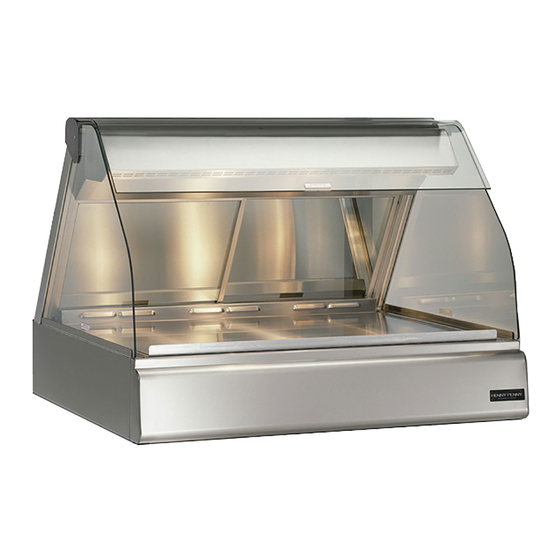
Heated merchandiser
Hide thumbs
Also See for HMR-103:
- Specifications (1 page) ,
- Brochure (12 pages) ,
- Operator's manual (23 pages)
Advertisement
2-1. INTRODUCTION
2-2. UNPACKING
203
SECTION 2. INSTALLATION
This section provides the installation instructions for the Henny
Penny Heated Merchandiser.
Installation of this unit should be performed only by a qualified
service technician.
Do not puncture the heated merchandiser with any objects
such as drills or screws as component damage or electrical
shock could result.
The Henny Penny Heated Merchandiser is tested, inspected and
expertly packed to ensure arrival at its destination in the best possible
condition. The unit has been bolted to wooden skid. All items have
been packed and taped inside of the unit. The unit is then packed
inside a triple wall corrugated carton with sufficient padding to with-
stand normal shipping treatment.
Any shipping damage should be noted in the presence of the
delivery agent and signed prior to his or her departure.
To remove the heated merchandiser from the carton, you should:
1. Carefully cut banding straps.
2. Open flaps of carton and remove packing.
3. Lift carton from unit.
4. Remove four bolts mounting the merchandiser to the skid.
5. If installing the unit on a merchandiser base, use existing bolts to
mount unit.
6. Unpack doors, cutting board, and pan supports, and install.
7. The heated merchandiser is now ready for location and setup.
Model HMR-103,104,105,106,107
2-1
Advertisement
Table of Contents

Subscribe to Our Youtube Channel
Related Manuals for Henny Penny HMR-103


Summary of Contents for Henny Penny HMR-103
-
Page 1: Section 2. Installation
The Henny Penny Heated Merchandiser is tested, inspected and expertly packed to ensure arrival at its destination in the best possible condition. The unit has been bolted to wooden skid. All items have been packed and taped inside of the unit. -
Page 2: Electrical Connection
The equipotential lug is marked with the following symbol A separate disconnect switch with proper capacity fuses or breakers must be installed at a convenient location between the unit and the power source. Model HMR-103,104,105,106,107 1004... -
Page 3: Electrical Data Table
COMBI- 1 PHASE 3 PHASE MODEL NATION HMR-107 3F/2S/2F* HMR-107 2S/3F/2S HMR-107 2F/3S/2F HMR-106 HMR-106 HMR-106 4S/2F* HMR-106 4F/2S* Model HMR-103,104,105,106,107 AMPS VOLTS 1 PHASE 3 PHASE 120/208 120/240 220-240 380-415 120/208 120/240 220-240 380-415 120/208 120/240 220-240 380-415 120/208... - Page 4 *Well modules can be arranged in opposite order AMPS COMBI- 1 PHASE 3 PHASE MODEL NATION HMR-105 3F/2S* (Cont.) HMR-104 HMR-104 HMR-104 2S/2F* HMR-103 HMR-103 Model HMR-103,104,105,106,107 AMPS VOLTS 1 PHASE 3 PHASE 120/208 120/240 220-240 380-415 120/208 120/240 220-240 380-415 120/208 120/240 220-240...
-
Page 5: Cabinet Dimensions
Model HMR-103,104,105,106,107 2-5. CABINET DIMENSIONS... - Page 6 1. Notice the location of the bracket on unit, as indicated. 2. Using a 3/8” socket, or nut driver, loosen the 2 acorn nuts securing the bracket, but do not remove. 3. Slide bracket off from around the 2 acorn nuts. Model HMR-103,104,105,106,107 1202...
- Page 7 2-6. CENTER GLASS INSTALLATION (Continued) 1202 4. Place glass in divider track as shown. 5. Slide bracket onto glass and align to its original position around the 2 acorn nuts. 6. Retighten the 2 acorn nuts. Model HMR-103,104,105,106,107...
-
Page 8: Side Glass
3. Align the hole in the glass with the plunger of the retainer. 4. Turn the plunger of the retainer clockwise again, to lock and release the plunger in place. 5. Installation is now complete. Model HMR-103,104,105,106,107 1202...
Need help?
Do you have a question about the HMR-103 and is the answer not in the manual?
Questions and answers