
Related Manuals for Henny Penny HCS-2


Summary of Contents for Henny Penny HCS-2
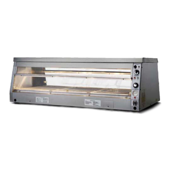
- Page 1 Henny Penny Humidified Counter Warmer Model HCW-2 Model HCS-2 Model HCW-3 Model HCW-5 Model HCS-5 Model HCW-8 TECHNICAL MANUAL...
-
Page 3: Table Of Contents
3-4. How to Order ... 3-1 3-5. Prices ... 3-2 3-6. Delivery ... 3-2 3-7. Warranty ... 3-2 3-8. Recommended Spare Parts for Distributors ... 3-2 3-9. Parts List ... 3-4 Model HCS-2,HCW-3/HCW-5/HCW-8 TABLE OF CONTENTS FM06-016 Revised 1-26-09 Page... -
Page 5: Section 1. Troubleshooting
SECTION 1. TROUBLESHOOTING 1-1. INTRODUCTION 1-2. SAFETY 1-3. TROUBLESHOOTING Model HCS-2,HCW-3/HCW-5/HCW-8 The section provides troubleshooting information in the form of an easy to read table. If a problem occurs during the first operation of a new cabinet, recheck the Installation section of the Operator’s Manual. - Page 6 Radiant heat not high enough • Radiant heat not working • Water temperature too high • Model HCS-2,HCW-3/HCW-5/HCW-8 CORRECTION Insert bulb in block • Replace per Thermometer • section Keep doors closed when •...
-
Page 7: Water System
No neutral supplied in field • wiring Loose or defective wiring • Faulty light bulbs • Faulty light switch • Model HCS-2,HCW-3/HCW-5/HCW-8 CORRECTION Check float switch per • Float Switch section Check water control switch • per Water Control Switch section Check water valve per •... - Page 8 • Bun pans are not over water • Faulty infinite regulator • Faulty power switch • Faulty radiant heater • Model HCS-2,HCW-3/HCW-5/HCW-8 CORRECTION Replace contactor per • Contactor section Check thermostat per • Thermostat section Check high limit switch per •...
-
Page 9: Section 2. Maintenance
Light bulbs and glass may be hot. Severe burns could result. 1. Remove the glass panel by carefully pushing up on back of panel and sliding away from you. The panel will fall into your hand. 2. Remove the light bulb. Model HCS-2,HCW-3/HCW-5/HCW-8... -
Page 10: Fuse
(Continued) 2-4. FUSE 2-5. CLEANING WATER STRAINER Model HCS-2,HCW-3/HCW-5/HCW-8 3. Replace the light bulb with a Westinghouse #60A19/35, 130 Volt bulb. If this bulb is not available, a standard 60 watt bulb will work until a long life bulb can be obtained. - Page 11 STRAINER (Continued) Step 4 Step 4 Step 5 Model HCS-2,HCW-3/HCW-5/HCW-8 3. Remove the control side end panel. 4. Remove the hex cap at the bottom of the water strainer. 5. Remove the screen from inside the strainer and clean. 6. Reassemble in reverse order.
-
Page 12: Water Strainer (Replacement)
2-6. WATER STRAINER (REPLACEMENT) 2-7. WATER VALVE Model HCS-2,HCW-3/HCW-5/HCW-8 1. Remove electrical power supplied to the cabinet. To avoid electrical shock or property damage, move the power switch to OFF and disconnect main circuit breaker, or unplug cord at wall receptacle. - Page 13 (Continued) Step 7 Step 9 Step 10 Model HCS-2,HCW-3/HCW-5/HCW-8 4. Check across terminals of the water valve with an ohmmeter. The meter reading should be 600-650, if reading is not correct replace the water valve by continuing with this procedure.
-
Page 14: Float Switch
2-8. FLOAT SWITCH Step 6 Model HCS-2,HCW-3/HCW-5/HCW-8 1. Remove electrical power supplied to the cabinet. To avoid electrical shock or property damage, move the power switch to OFF and disconnect main circuit breaker, or unplug cord at wall receptacle. 2. Drain the water pan by removing the drain standpipe. -
Page 15: Light Switch
2-8. FLOAT SWITCH (Continued) 2-9. LIGHT SWITCH Step 3 Model HCS-2,HCW-3/HCW-5/HCW-8 8. Strip the wire ends that were cut, as well as the wire ends on the new float switch. Reconnect wires using wire nuts. 9. Replace the end panel. -
Page 16: Power Switch
2-10. POWER SWITCH Step 3 Model HCS-2,HCW-3/HCW-5/HCW-8 1. Remove electrical power supplied to the cabinet. To avoid electrical shock or property damage, move the power switch to OFF and disconnect main circuit breaker, or unplug cord at wall receptacle. 2. Remove the control side end panel. -
Page 17: Water Control Switch
2-11. WATER CONTROL SWITCH Step 3 2-12. INFINITE SWITCH Model HCS-2,HCW-3/HCW-5/HCW-8 1. Remove electrical power supplied to the cabinet. To avoid electrical shock or property damage, move the power switch to OFF and disconnect main circuit breaker, or unplug cord at wall receptacle. -
Page 18: Thermostat
Step 3 2-13. THERMOSTAT Step 3 2-10 Model HCS-2,HCW-3/HCW-5/HCW-8 3. Remove the electrical wires from the switch. 4. Remove the switch knob by pulling it off. 5. Remove the nut from the control panel side of the switch and remove the switch. -
Page 19: Indicating Light
(Continued) Step 5 Step 6 2-14. INDICATING LIGHT Model HCS-2,HCW-3/HCW-5/HCW-8 5. Remove the sensor bulb by pulling on the capillary tube. 6. Remove the two mounting screws from the thermostat. 7. Install a new thermostat in reverse order. 8. Replace the end panel. -
Page 20: Thermometer
2-15. THERMOMETER Step 3 Step 4 2-12 Model HCS-2,HCW-3/HCW-5/HCW-8 3. Cut the light wires just behind the light housing. 4. Squeeze the plastic retainers on the light body and push the light through the control panel. 5. Install a new light by pushing the light through the control panel until the light snaps securely in the panel. -
Page 21: Contactor
2-16. CONTACTOR Model HCS-2,HCW-3/HCW-5/HCW-8 1. Remove electrical power supplied to the cabinet. To avoid electrical shock or property damage, move the power switch to OFF and disconnect main circuit breaker, or unplug cord at wall receptacle. 2. Remove the control side panel. -
Page 22: Terminal Block
2-17. TERMINAL BLOCK Step 5 2-14 Model HCS-2,HCW-3/HCW-5/HCW-8 1. Remove electrical power supplied to the cabinet. To avoid electrical shock or property damage, move the power switch to OFF and disconnect main circuit breaker, or unplug cord at wall receptacle. -
Page 23: Water Pan Heater
2-18. WATER PAN HEATER Step 2 Step 3 Model HCS-2,HCW-3/HCW-5/HCW-8 1. Remove electrical power supplied to the cabinet. To avoid electrical shock or property damage, move the power switch to OFF and disconnect main circuit breaker, or unplug cord at wall receptacle. -
Page 24: Radiant Heater
2-19. RADIANT HEATER Step 2 Step 3 2-16 Model HCS-2,HCW-3/HCW-5/HCW-8 1. Remove electrical power supplied to the cabinet. To avoid electrical shock or property damage, move the power switch to OFF and disconnect main circuit breaker, or unplug cord at wall receptacle. -
Page 25: Light Socket
2-20. LIGHT SOCKET Step 3 2-21. HIGH LIMIT SWITCH Model HCS-2,HCW-3/HCW-5/HCW-8 1. Remove electrical power supplied to the cabinet. To avoid electrical shock or property damage, move the power switch to OFF and disconnect main circuit breaker, or unplug cord at wall receptacle. -
Page 26: Conversion
Step 4 Step 5 2-22. CONVERSION 2-18 Model HCS-2,HCW-3/HCW-5/HCW-8 3. Check the high limit switch by determining the continuity of the high limit. The continuity check can be made at the terminals where the two high limit wires are connected (one wire goes to the thermostat and the other goes to L1 on the quick-connect terminal block). - Page 27 2-22. CONVERSION (Continued) Step 3 Model HCS-2,HCW-3/HCW-5/HCW-8 3. Remove four (4) nuts holding top cap. 4. Remove top cap. 5. Set HCW-2 in place by using same stud holes which the top cap used. 6. Install four (4) nuts which held top cap to retain HCW-2.
- Page 28 2-22. CONVERSION (Continued) 2-20 Model HCS-2,HCW-3/HCW-5/HCW-8 Connect the wire coming from the fuse in the HCW-2 • to the L screw-clamp terminal block. This should make a total of 3 wires in this block. By using a two-blade quick-connect adaptor, connect •...
-
Page 29: Wiring Diagrams
Model HCS-2,HCW-3/HCW-5/HCW-8 2-23. WIRING DIAGRAMS (SN: JA0705006 & Above) 2-21... - Page 30 Model HCS-2,HCW-3/HCW-5/HCW-8 2-23. WIRING DIAGRAMS (Continued) (SN: JA0705006 & Above) 2-22...
- Page 31 Model HCS-2,HCW-3/HCW-5/HCW-8 2-23. WIRING DIAGRAMS (Continued) (SN: JA0705006 & Above) 2-23...
- Page 32 Model HCS-2,HCW-3/HCW-5/HCW-8 2-23. WIRING DIAGRAMS (Continued) (SN: JA0705006 & Above) 2-24...
- Page 33 Model HCS-2,HCW-3/HCW-5/HCW-8 2-23. WIRING DIAGRAMS (Continued) (SN: JA0705006 & Above) 2-25...
- Page 34 Model HCS-2,HCW-3/HCW-5/HCW-8 2-23. WIRING DIAGRAMS (Continued) (SN: JA0705006 & Above) 2-26...
- Page 35 Model HCS-2,HCW-3/HCW-5/HCW-8 2-23. WIRING DIAGRAMS (Continued) (SN: JA0705006 & Above) 2-27...
- Page 36 Model HCS-2,HCW-3/HCW-5/HCW-8 2-23. WIRING DIAGRAMS (Continued) (SN: JA0705006 & Above) 2-28...
- Page 37 Model HCS-2,HCW-3/HCW-5/HCW-8 2-23. WIRING DIAGRAMS (Continued) (SN: JA0705006 & Above) 2-29...
- Page 38 2-23. WIRING DIAGRAMS (Continued) (SN: JA0705006 & Above) 2-30...
- Page 39 Model HCS-2,HCW-3/HCW-5/HCW-8 2-23. WIRING DIAGRAMS (Continued) (SN: JA0705006 & Above) 2-31...
- Page 40 Model HCS-2,HCW-3/HCW-5/HCW-8 2-23. WIRING DIAGRAMS (Continued) (SN: JA0705006 & Above) 2-32...
- Page 41 Model HCS-2,HCW-3/HCW-5/HCW-8 2-23. WIRING DIAGRAMS (Continued) (SN: JA0705006 & Above) 2-33...
- Page 42 Model HCS-2,HCW-3/HCW-5/HCW-8 2-23. WIRING DIAGRAMS (Continued) (SN: JA0705006 & Above) 2-34...
- Page 43 Model HCS-2,HCW-3/HCW-5/HCW-8 2-23. WIRING DIAGRAMS (Continued) 1006 2-35...
- Page 44 Model HCS-2,HCW-3/HCW-5/HCW-8 2-23. WIRING DIAGRAMS (Continued) 2-36...
- Page 45 Model HCS-2,HCW-3/HCW-5/HCW-8 2-23. WIRING DIAGRAMS (Continued) 2-37...
- Page 46 Model HCS-2,HCW-3/HCW-5/HCW-8 2-23. WIRING DIAGRAMS (Continued) 2-38...
- Page 47 Model HCS-2,HCW-3/HCW-5/HCW-8 2-23. WIRING DIAGRAMS (Continued) 2-39...
- Page 48 Model HCS-2,HCW-3/HCW-5/HCW-8 2-23. WIRING DIAGRAMS (Continued) 2-40...
- Page 49 2-23. WIRING DIAGRAMS (Continued) 1006 2-41...
- Page 50 Model HCS-2,HCW-3/HCW-5/HCW-8 2-23. WIRING DIAGRAMS (Continued) 2-42...
- Page 51 During this time, any frypot that fails due to manufacturing or workmanship issues will be replaced at no charge for parts, labor, or freight. Henny Penny will either install a new frypot at no cost or provide a new or reconditioned replacement fryer at no cost.
-
Page 52: Model Hcw
This section lists the replaceable parts of Henny Penny Model HCW-3, HCW-5, and HCW-8 display cabinets. Use only genuine Henny Penny parts in your cabinet. Using a part of lesser quality or substitute design may result in cabinet damage or personal injury. -
Page 53: Prices
Commonly replaced items are stocked by your distributor and will be sent out when your order is received. Other parts will be ordered by your distributor from Henny Penny Corporation. Normally, these will be sent to your distributor within three working days. - Page 54 Model HCS-2,HCW-3/HCW-5/HCW-8...
-
Page 55: Model Hcs
Pivot - Side Nut - 1/4-20 Hex Kep Screw #8-32 x 5/8” PH 100 Fhd. S Extrusion - HCW - Door Extrusion - HCS-2 - Door Lockwasher - #8 Internal Nut - (#8-32 Acorn) Top Decorator Panel Assembly Top Decorator Panel Assembly-... - Page 56 Item Part Number 22549 Reflector - Heater Housing 39989 Reflector - Heater Housing - HCW-8 72203 Reflector - Heater Housing - HCS-2 22536 Cover - Terminal 22578 Deflector - Heater 39935 Deflector - Heater - HCW-8 72204 Deflector - Heater - HCS-2 √...
- Page 57 22560 Pan Support - Bottom 54263 Pan Support - Bottom - HCW-8 72188 Pan Support - Bottom - HCS-2 41556 Viewing Panel Bracket Assembly (R.H.) NS03-017 Nut - #8 U-Type Clip - SN: IR022JB and below √ √ √ √ √ 70...
- Page 58 Breaker - Push Button Reset (SN: JA0705006 & above) Nut - #6-32 Hex Keps Infinite Regulator Top Cap Assembly Top Cap Assembly - HCW-8 Top Cap Assembly - HCS-2 Nut - Infinite Regulator Knob - Infinite Switch Support - Glass Support - Glass - HCW-8...
- Page 59 Part Number 54193* 54197* 38774* 38742* 38773* 38926* 38743* 38737* 38742* 38745* 38740* 38739* 54195* 38744* 38741* 38738* 38705* 38702* NS02-006* NS03-023* WA01-013* 14629* 1006 HCW-8 Only Parts List Description Brace Weldment Upper w/Rack Support Brace Weldment - Upper Door Assembly - 30" - Middle - Top Door - 30"...
Need help?
Do you have a question about the HCS-2 and is the answer not in the manual?
Questions and answers