Table of Contents
Advertisement
Advertisement
Table of Contents

Related Manuals for Lowrance X-4


Summary of Contents for Lowrance X-4
- Page 1 Fish-Finding Sonar Installation and Operation Instructions...
- Page 2 Navico. Any unauthorized commercial distribution of this manual is strictly prohibited. Lowrance is a registered trademark of Navico. ® Navico may find it necessary to change or end our policies, regulations, and special offers at any time.
-
Page 3: Table Of Contents
Table of Contents Specifications: X-4 ................iii Preparations ..................1 Transducer Installation ............... 1 Selecting a Transducer Location ............. 2 How low should you go? ..............4 Transom Transducer Assembly And Mounting ......4 Trolling Motor Bracket Installation (single-frequency only) ..10 Transducer Orientation and Fish Arches ........ - Page 4 Battery Alarm ..................32 Noise Reject and ASP™ ..............33 Depth Display ..................33 Voltage ....................34 Temperature Display ................. 34 Units ....................34 Backlight ..................... 35 Contrast ....................35 Simulator .................... 36 Set Language ..................36 Software Information ................. 36 Reset Options ..................
- Page 5 Specifications: X-4 General Case size: ......5.8" H x 4.3" W x 2.5" D (14.7 cm H x 10.8 cm W x 6.6 cm D) sealed, waterproof; suitable for saltwater use. Display: ......High-contrast Film SuperTwist LCD. Di- agonal viewing area: 3.5" (8.9 cm).
- Page 6 Depth display: ....Continuous digital readout. Audible alarms: ....Deep/shallow/fish. Automatic ranging: ..Yes, with instant screen updates. Auto bottom track: ..Yes. Zoom bottom track: ..Yes. Split-screen zoom: ..No. Surface water temp: ..Yes, built into transducer. Optional external temperature sensor or combo speed/temp sensor available.
-
Page 7: Preparations
Transducer Installation Preparations You can install the sonar in some other order if you prefer, but we rec- ommend this installation sequence: Caution: You should read over this entire installation section before drill- ing any holes in your vehicle or vessel! 1. -
Page 8: Selecting A Transducer Location
These are all "kick-up" mounting brackets. They help prevent damage if the transducer strikes an object while the boat is moving. If the transducer does "kick-up," the bracket can easily be pushed back into place without tools. Read these instructions carefully before attempting the installation. Determine which of the mounting positions is right for your boat. - Page 9 NOTE: Some aluminum boats with strakes or ribs on the outside of the hull create large amounts of turbulence at high speed. These boats typically have large outboard motors capable of propelling the boat at speeds faster than 35 mph. Typically, a good transom location on aluminum boats is between the ribs closest to the engine.
-
Page 10: How Low Should You Go
How low should you go? For most situations, you should install your Skimmer transducer so that its centerline is level with the bottom of the boat hull. This will usually give you the best combination of smooth water flow and protection from bangs and bumps. Transom Transducer centerline... - Page 11 The following instructions sometimes vary depending on the mounting bracket that came with your transducer. Single-frequency Skimmers come with a one-piece stainless steel bracket, while dual-frequency Skimmers come with a two-piece plastic mounting bracket. Use the set of instruc- tions that fits your model. 1.
-
Page 12: Aligning The Transducer On The Transom
Alignment letters Alignment positions Transducer Transducer bracket Insert and align ratchets. Transducer Transducer bracket Ratchet Ratchet Add ratchets to bracket and transducer. 2. Aligning the transducer on the transom. To align the transducer to the transom, side the transducer between the ratchets. -
Page 13: Assembling The Transducer
If the transducer's face isn't parallel with the ground, remove the transducer and ratchets from the bracket. Place the ratchets into the holes in the bracket with the letter "B" aligned with the dot stamped in the bracket. Reassemble the transducer and bracket and place them against the transom. - Page 14 washer Rubber Metal washer washers Bolt Assemble transducer and bracket. B. Two-piece bracket: Once you determine the correct position for the ratchets, assemble the transducer as shown in the figure in step 2B. Don't tighten the lock nut at this time. Lock washer Bolt Flat washer...
- Page 15 Mark the center of each slot for the mounting screw pilot holes. You will drill one hole in the center of each slot. Drill the holes. For the one-piece bracket, use the #29 bit (for the #10 screws). For the two-piece bracket, use the #20 bit (for the #12 screws). 5.
-
Page 16: Trolling Motor Bracket Installation (Single-Frequency Only)
If possible, route the transducer cable away from other wiring on the boat. Use caution when routing the transducer cable around these wires. WARNING: Clamp the transducer cable to the transom close to the transducer. This can prevent the transducer from enter- ing the boat if it is knocked off at high speed. -
Page 17: Transducer Orientation And Fish Arches
Internal tooth washer Bolt Flat washer Attach motor mounting bracket to transducer. 3. Route the transducer cable alongside the trolling motor shaft. Use plastic ties (not included) to attach the transducer cable to the trol- ling motor shaft. Make sure there is enough slack in the cable for the motor to turn freely. - Page 18 Partial fish arches Transducer aimed Transducer aimed too far back too far forward Full fish arch Proper transducer angle Transducer angles and their effects on fish arches. If the arch slopes up – but not back down – then the front of the trans- ducer is too high and needs to be lowered.
-
Page 19: Power Connections (Permanent Mount Only)
Power Connections (permanent mount only) The unit works from a 12-volt battery system. You can attach the pow- er cable to your boat's accessory or power buss (or directly to the bat- tery). If you use an accessory buss but have problems with electrical interference, attach the power cable directly to the battery. -
Page 20: Mounting The Sonar Unit: In-Dash, Bracket Or Portable
This unit can be installed in a dash with the optional FM-6 in- dash adapter kit. The FM-6 kit includes an instruction sheet, part 988- 0147-631, which contains a template for cutting out the mounting hole. This document can be downloaded free from the www.lowrance.com web site. -
Page 21: Bracket Installation
(See the following drawings, which show the dimensions of a gimbal-mounted X-4 sonar unit.) 82.7 107.5 [3.26] [4.23] [6.26] 12.09 [0.48] 76.9 Millimeter 70.3 [3.03] [Inch] [2.77] Front view (left) and side view (right) showing dimensions of the X-4 when mounted on quick release bracket. - Page 22 Holes in the bracket’s base allow wood screw or through-bolt mounting. You may need to place a piece of plywood on the back side of thin pa- nels to reinforce the panel and secure the mounting hardware. Drill a 1" (25.4 mm) hole in the dash for the power/transducer and ac- cessory cables.
-
Page 23: Portable Sonar Installation
Portable Sonar Installation Like many Lowrance products, the X-4 sonar is capable of portable op- eration. It uses the optional PPP-12 portable power pack. The PPP-12 package includes the power pack, battery adapter and a port- able transducer. -
Page 24: Installing The Batteries
To use a portable power pack, you install the batteries and then attach the sonar unit to the power pack's bracket. Plug in the pow- er/transducer cable and you're ready to fish. The PPP-12 has a quick-release mounting bracket built into the case. Installing the Batteries Open the case and lay it flat. -
Page 25: Mounting The Unit
the power cable plug. This may result in corrosion of the plug body along with the electrical contacts in the cable and the unit's power socket. Mounting the Unit A quick-release mount is built into the top of the portable power pack. To attach the unit, first plug in the cable connector. -
Page 26: Portable Transducer Assembly
Portable Transducer Assembly Make sure there is one washer on each side of the transducer, inside the bracket. Slide the other washer over the end of the bolt and screw on the nut. Screw the suction cup onto the bracket using the supplied screw and flat washer. - Page 27 nylon cord here Screw Suction Bolt Washer Washer Transducer Portable transducer assembly: rear view (left) and side view (right). NOTE: For optimum operation, the portable transducer should be adjusted so that it is parallel to the ground. For more information on this, see the segment in the unit's operation manual on Transducer Orientation and Fish Arches.
-
Page 28: Operation
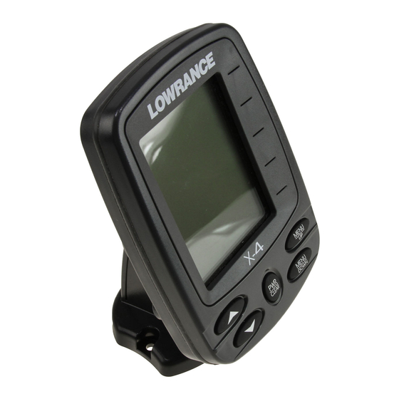
Operation Keyboard Basics The X-4 has five buttons including, Power/Clear, Menu Up, Menu Down and two arrow keys. PWR/CLEAR Press the key to turn the unit on and off. It also clears menus and menu selections from the screen. MENU UP & MENU DOWN key cycles forward through the menus. -
Page 29: Full Chart
Digital depth Surface signal Water Temp Fish symbols Bottom signal Structure or cover Depth range at bottom of ® Grayline depth scale Full Chart page. Fish I.D. (fish symbols) is on by default. Full Chart On the Full Chart page, the bottom signal scrolls across the screen from right to left. -
Page 30: Depth Range
Depth Range Depth Range has two modes: Automatic and Manual. In auto range mode, the unit always keeps the bottom displayed in the lower portion of the screen. If you want to manually select a depth range, you can override automatic depth range control. Depth Range menu with Manual setting selected (left). -
Page 31: Sensitivity
You can tell when the display is in Zoom mode because the top depth scale on the left of the screen will no longer show zero. If the current range is 0 to 80 feet, turning on the zoom feature will magnify the water column between 40 feet to 80 feet. -
Page 32: Grayline
Sensitivity set to manual mode (left). Sensitivity control bar (right). To adjust sensitivity in Auto Mode: 1. Press until the control bar appears. Press to increase ↑ MENU ENSITIVITY the sensitivity, to decrease it. ↓ 2. Press to clear the menu. If you reach the maximum or minimum sensitivity level, a tone will sound. - Page 33 Bait school Fish arches Sensitivity at 71 percent (left). Sensitivity at 100 percent (right). To change the Grayline level: 1. Press until the control bar appears. MENU RAYLINE 2. Press to increase the level of Grayline or press to decrease it. If ↑...
-
Page 34: Chart Speed
Chart Speed The rate that echoes scroll across the screen is called the chart scroll speed. The default for this unit is the maximum, 100 percent. Chart Speed control bar. NOTE: When you are stationary or traveling slowly and using a higher chart speed, a fish swimming through the sonar signal will be dis- played as a long line instead of a fish arch. -
Page 35: Fishtrack
To see what's under your boat in maximum detail, we recommend you turn off Fish I.D. and begin learning to interpret fish arches. To turn Fish I.D. on/off: 1. Press until the menu appears. Press to select ↓ MENU 2. Press to clear the menu from the display. -
Page 36: Depth Alarms
To turn on/off the fish alarm: 1. Press until the menu appears. Press to select ↑ MENU LARM 2. Press to clear the menu from the screen Fish ID menu and symbol with FishTrack on (left). Fish Alarm menu (right). Depth Alarms The depth alarms consist of a shallow and a deep alarm. -
Page 37: Deep Alarm
3. Press to return to the Shallow Alarm menu. Use to select ↑ which will turn on the alarm, then press to clear the menu. When the alarm goes off a message will appear and a tone will sound. Press to silence the alarm. -
Page 38: Battery Alarm
To turn off the alarm: 1. Repeatedly press until the menu appears. Press ↓ MENU LARM . Press to clear the menu. Battery Alarm To set the Battery alarm: 1. Press repeatedly until appears. MENU ATTERY LARM 2. Press the . -
Page 39: Noise Reject And Asp
Noise Reject and ASP™ The ASP™ (Advanced Signal Processing) feature is a noise rejection system that constantly evaluates the effects of boat speed, water condi- tions and electrical interference and automatically gives you the best display possible under most conditions. The ASP feature has three set- tings —... -
Page 40: Voltage
Voltage The Voltage menu allows you to display battery voltage in a small or medium size, or can be turned off completely. To display battery voltage: 1. Repeatedly press until the menu appears. Use ↑ ↓ MENU OLTAGE select the size of the voltage display. 2. -
Page 41: Backlight
To change units of measure: 1. Press until the menu appears. Use the arrow keys to se- MENU NITS lect the desired unit of measure. 2. Press the key to clear the menu. Backlight Turning on your unit's backlight will allow you to use it at night. To turn the backlight on/off: 1. -
Page 42: Simulator
Simulator This unit has a simulator that displays a simulated bottom signal with fish signals. To turn on/off the simulator: 1. Repeatedly press until the menu appears. Press ↑ ↓ MENU IMULATOR to turn it on or off. 2. Press to clear the menu. -
Page 43: Accessory Ordering Information
Accessory Ordering Information for all countries To order Lowrance GPS accessories such as computer cables or MMC cards, please contact: 1) Your local marine dealer or consumer electronics store. Most quality dealers that handle marine electronic equipment or other consumer electronics should be able to assist you with these items. - Page 44 Visit our web site: www.lowrance.com © Copyright 2010 *988-10014-001* All Rights Reserved Navico Holding AS.
Need help?
Do you have a question about the X-4 and is the answer not in the manual?
Questions and answers
Does this unit record boat speed
The Lowrance X-4 does not record boat speed, but its Skimmer® transducer operates at boat speeds up to 70 mph (61 kts).
This answer is automatically generated