Table of Contents
Advertisement
Quick Links
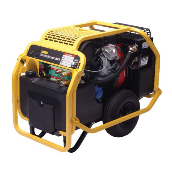
GTR20
Stanleyrailwayproducts
HYDRAULIC
POWER UNIT
WARNING
WARNING
To avoid serious injury or death
S
, O
M
AFETY
PERATION AND
AINTENANCE
USER'S MANUAL
Stanley Hydraulic Tools
3810 SE Naef Road
Milwaukie OR 97267-5698
503-659-5660
Copyright
©
2006, The Stanley Works
FAX 503-652-1780
USER USA
www.stanley-hydraulic-tools.com
65114 9/2006 Ver 3
1
Advertisement
Table of Contents
Troubleshooting

Related Manuals for Stanley GTR20


Summary of Contents for Stanley GTR20
- Page 1 WARNING WARNING To avoid serious injury or death AFETY PERATION AND AINTENANCE USER’S MANUAL Stanley Hydraulic Tools 3810 SE Naef Road Milwaukie OR 97267-5698 503-659-5660 Copyright © 2006, The Stanley Works FAX 503-652-1780 USER USA www.stanley-hydraulic-tools.com 65114 9/2006 Ver 3...
-
Page 3: Table Of Contents
REPAIRS AND / OR SERVICE TO THIS TOOL MUST ONLY BE DONE BY AN AUTHORIZED AND CERTIFIED DEALER. For the nearest authorized and certifi ed dealer, call Stanley Hydraulic Tools at the number listed on the back of this manual and ask for a Customer Service Representative. -
Page 4: Safety Symbols
SAFETY SYMBOLS Safety symbols and signal words, as shown below, are used to emphasize all operator, maintenance and repair actions which, if not strictly followed, could result in a life-threatening situation, bodily injury or damage to equip- ment. This is the safety alert symbol. It is used to alert you to potential personal injury hazards. -
Page 5: Safety Precautions
In addition to this manual, read and understand safety and operating instructions in the Engine Operation Manual furnished with the power unit. The GTR20 Hydraulic Power Unit will provide safe and dependable service if operated in accordance with the instructions given in this manual. Read and understand this manual and any stickers and tags attached to the Power Unit. -
Page 6: Tool Stickers & Tags
TOOL STICKERS & TAGS 59126 Power Unit Dash Decal 59125 Dual Circuit Decal 59126 59125... -
Page 7: Hydraulic Hose Requirements
HOSE SAFETY TAGS To help ensure your safety, the following DANGER tags are attached to all hose purchased from Stanley Hydrau- lic Tools. DO NOT REMOVE THESE TAGS. -
Page 8: Htma Requirements
HTMA REQUIREMENTS TOOL CATEGORY HYDRAULIC SYSTEM REQUIREMENTS TYPE I TYPEII TYPEIII TYPE RR FLOW RATE 4-6 gpm 7-9 gpm 11-13 gpm 9-10.5 gpm (15-23 lpm) (26-34 lpm) (42-49 lpm) (34-40 lpm) TOOL OPERATING PRESSURE 2000 psi 2000 psi 2000 psi 2000 psi (at the power supply outlet) (138 bar) -
Page 9: Operation
1. ENGINE CRANKCASE OIL LEVEL growth that may occur in cool operating hydraulic circuits. These fl uids are recommended by Stanley. Other fl uids Always check the oil level before starting the engine. Make that meet or exceed the specifi cations of these fl uids may sure the oil level is at the FULL MARK on the dipstick. - Page 10 OPERATION from the male to the female quick disconnect as shown in fi gure 2. Quick disconnect couplings and hose fi ttings are VALVE BLOCK selected so that additional fi ttings such as reducer or adapter fi ttings are not required. PRESSURE PRESSURE If adapter fi...
-
Page 11: Controls
OPERATION has selected with the fl ow selector switch. When a tool is CONTROLS not being used the engine will not return to idle until either the fl ow selector switch is turned to the OFF position or the This unit is equipped with an advanced proportional engine throttle control switch is turned to AUTO-ON. -
Page 12: Cold Weather Startup
OPERATION 2. Unless already at idle the power unit should return to FOR 5 GPM OPERATION idle. This may take a few seconds for the unit to react due to a built-in program delay. For 5 gpm operation, select mode of operation with the Throttle Control switch, either auto-idle-on or the auto-idle- 3. -
Page 13: Routine Maintenance
ROUTINE MAINTENANCE ENGINE MAINTENANCE the hydraulic tank, avoiding the water at the bottom of the container. Follow the maintenance schedule and general maintenance instructions in the engine maintenance and operation • Each day, check hydraulic lines and fi ttings for leaks, manual furnished with the power unit. -
Page 14: Programmable Controller
ACT is a PC (personal computer) based software calibration and monitoring tool. ACT is designed The Stanley controller is capable of identifying certain fault specifi cally for use with engines equipped with conditions and alerting the user to them. A fl ashing LED the Stanley controller. - Page 15 CODE FAULT SHUTDOWN CORRECTIVE ACTION APECS unit not calibrated Have engine serviced by an Authorized Stanley Dealer. Engine speed excessive Have engine serviced by an Authorized Stanley Dealer. Engine speed unusually low Have engine serviced by an Authorized Stanley Dealer.
-
Page 16: Testing The Hydraulic Circuit
1. Set the fl ow selector switches to the OFF (center) posi- tion. 2. Set the throttle control switch to AUTO-OFF position. 3. Connect the Stanley Circuit Tester across two hose ends (where the tool would normally be connected). 4. Fully open the tester restrictor valve (counterclockwise). -
Page 17: Troubleshooting
TROUBLESHOOTING PROBLEM CAUSE REMEDY Engine will not start. Flow selector switch not in the Make sure both fl ow selector switches OFF position. are in the OFF position when starting. Battery not connected. Attach battery cables, check wires. Weak battery. Test battery, charge or replace. -
Page 18: Specifications
SPECIFICATIONS Engine: ............................18 hp Briggs / 20 hp Honda Capacity..................Two 5 gpm/19 lpm Circuits or One 10 gpm/37.8 lpm Circuit Length:................................36 in. / 91.4 cm Width: ................................23 in: / 58.4 cm Height: ................................29.5 in. / 74.9cm Weight (Wet): Dual Circuit Briggs ....................334 lbs / 151.5 kg Weight (Wet): Dual Circuit Honda ....................352 lbs / 159.6 kg Fuel Tank Capacity: ............................ - Page 19 FIGURE 1. BRIGGS ENGINE ASSEMBLY...
- Page 20 FIGURE 1. BRIGGS ENGINE PARTS LIST ITEM DESCRIPTION ITEM DESCRIPTION 65616 Engine Controller 36150 Muffl er 40433 Hex Flange Bolt 5/16-18 x 1/2 36151 Heat Shield 58897 Frame Base Weldment 36152 Screw, Hex Washer 58918 Wheel & Tire 59007 Briggs Engine 58917 Axle 56656...
- Page 21 FIGURE 1A. HONDA ENGINE ASSEMBLY...
- Page 22 FIGURE 1A. HONDA ENGINE PARTS LIST ITEM DESCRIPTION ITEM DESCRIPTION 38577 Muffl er Kit 18893 Flang Nut, 3/8-16 62292 Hex Washer Head Screw 58976 Hex Flange Bolt, 3/8-16 No Item 31240 Retaining Ring 36918 Honda Engine 21318 Washer, 3/4 56656 Coupling 59083 Blower Housing...
- Page 23 FIGURE 2. FRAME PARTS 12-VOLT PLUG WIRING HARNESS Receptacle Assy 64942 TO STARTER SOLENOID 12 VOLT ACCESSORY NOT EQUIPPED ON ALL MODELS. GROUND 25 AMP FUSE AVAILABLE AS AN ADD-ON BLACK IF ADDING 12 VOLT ACCESSORY, CUT AWAY LABEL AND PUNCH THROUGH DASH PANEL 12-VOLT RECEPTACLE ITEM...
- Page 24 FIGURE 3. HOSES, FITTINGS & CLAMPS ITEM DESCRIPTION 59085 Manifold Assy, Dual Circuit 59104 Hose Barb, 3/4 in. Hose x 3/4 in. Pipe 62199 Hose Clamp Elbow, 45° Straight Thread 350000 02773 Adapter 58569 Elbow, 90° 58943 Hose Connector, Straight Thread 350104 40364 Elbow, 45°...
- Page 25 FIGURE 4. ADDITONAL WIRING DIAGRAM FOR HONDA POWER UNITS ONLY HONDA ENGINEP TO ACTUATOR PLUG ON MAIN 36918 62407 POWER UNIT WIRING HARNESS MAGNETO WIRE (SEE PHOTO'S) 62108 ACTUATOR TO PICK-UP COIL (SEE PHOTO’S) FUEL SHUT-OFF TO FUEL SHUT-OFF ON MAIN POWER UNIT WIRING HARNESS - 62405 ENGINE KILL TO MAGNETO WIRE ON MAIN PPOWER UNIT...
- Page 26 FIGURE 4B. MAIN POWER UNIT WIRING HARNESS HARNESS PART NUMBER 62294 RED WIRE TO POSITIVE "+" TOOL CIRCUIT 1 SIDE HOUR METER SWITCH 2 WHITES “+” BLACK WIRE TO NEGATIVE “-” MULTI COLORS SIDE HOUR METER PLUG TO ROTARY START SWITCH TOOL CIRCUIT 1 SOLENOID AUTO IDLE...
- Page 27 FIGURE 4C. DUAL CIRCUIT WIRE HARNESS CONTROLLER PLUGS MAGNETO WIRE (GRAY) ACTUATOR PLUG (RED & GREEN WIRES) ENGINE OIL PRESSURE SWITCH (RED WIRE) GROUND WIRES (BLACK) ENGINE OIL PRESSURE SWITCH (ORANGE WIRE) ENGINE OIL PRESSURE SWITCH (YELLOW WIRE) PRESSURE SWITCH (YELLOW, BLUE) CIRCUIT 2 TO RELAY...
-
Page 28: Warranty
SEALS & DIAPHRAGMS: Seals and diaphragms installed in new tools are warranted to be free of defects in material and/or workmanship for a period of 6 months after the date of fi rst usage, or for a period of 2 years from the shipping date from Stanley, whichever period expires fi rst. - Page 29 Stanley Hydraulic Tools 3810 SE Naef Road Milwaukie OR 97267-5698 503-659-5660 FAX 503-652-1780 www.stanley-hydraulic-tools.com...
Need help?
Do you have a question about the GTR20 and is the answer not in the manual?
Questions and answers