Table of Contents
Advertisement
Model(s):
PALOMA-BL
PALOMA-BZ
PALOMA-GR
PALOMA-GY
• Important operating
a n d m a i n t e n a n c e
instructions included.
WARNING: If the information in these
instructions is not followed exactly, a fi re
or explosion may result causing property
damage, personal injury, or death.
• Do not store or use gasoline or other fl am-
mable vapors and liquids in the vicinity of
this or any other appliance.
• What to do if you smell gas
- Do not try to light any appliance.
- Do not touch any electrical switch. Do not
use any phone in your building.
- Immediately call your gas supplier from a
neighbor's phone. Follow the gas suppli-
er's instructions.
- If you cannot reach your gas supplier, call
the fi re department.
• Installation and service must be performed
by a qualifi ed installer, service agency, or the
gas supplier.
This appliance may be installed as an OEM installation in
manufactured home (USA only) or mobile home and must be
installed in accordance with the manufacturer's instructions and
the manufactured home construction and safety standard, Title
24 CFR, Part 3280 or Standard for Installation in Mobile Homes,
CAN/CSA Z240MH.
This appliance is only for use with the type(s) of gas indicated
on the rating plate.
CAUTION
DO NOT DISCARD THIS MANUAL
• Read, understand and follow
these instructions for safe
installation and operation.
Heat & Glo • Paloma • 7031-220 Rev. P • 10/08
Owner's Manual
Installation and Operation
• Leave this manual with
party responsible for use
and operation.
WARNING
HOT SURFACES!
Glass and other surfaces are hot during
operation AND cool down.
Hot glass will cause burns.
• Do not touch glass until it is cooled
• NEVER allow children to touch glass
• Keep children away
• CAREFULLY SUPERVISE children in same room as
fi replace.
• Alert children and adults to hazards of high temperatures.
High temperatures may ignite clothing or other fl ammable
materials.
• Keep clothing, furniture, draperies and other fl ammable
materials away.
In the Commonwealth of Massachusetts:
• installation must be performed by a licensed plumber
or gas fi tter;
See Table of Contents for location of additional
Commonwealth of Massachusetts requirements.
Installation and service of this appliance should be
performed by qualifi ed personnel. Hearth & Home
Technologies suggests NFI certifi ed or factory trained
professionals, or technicians supervised by an NFI
certifi ed professional.
Portland
Tested and
O-T L
Listed by
Oregon USA
C
US
OMNI-Test Laboratories, Inc.
1
Advertisement
Table of Contents

Related Manuals for Heat & Glo PALOMA-BL


Summary of Contents for Heat & Glo PALOMA-BL
- Page 1 Model(s): PALOMA-BL PALOMA-BZ PALOMA-GR PALOMA-GY • Important operating a n d m a i n t e n a n c e instructions included. WARNING: If the information in these instructions is not followed exactly, a fi re or explosion may result causing property damage, personal injury, or death.
-
Page 2: Homeowner Reference Information
Read this manual before installing or operating this appliance. Please retain this owner’s manual for future reference. Congratulations on selecting a Heat & Glo gas appliance —an elegant and clean alternative to wood burning appliances. The Heat & Glo gas appliance you have selected is designed to provide the utmost in safety, reliability, and effi... -
Page 3: Table Of Contents
1 Listing and Code Approvals A. Appliance Certifi cation ......4 B. Glass Specifi cations ......4 C. -
Page 4: Listing And Code Approvals
Listing and Code Approvals A. Appliance Certifi cation MODELS: Paloma LABORATORY: Omni Test Laboratories, Inc. TYPE: Vented Gas Fireplace Heater STANDARD: ANSI Z21.88B-2003 • CSA 2.33-2003 • UL307B CAN/CBA 2.17-M91 This product is listed to ANSI standards for “Vented Gas Appliance Heaters”... -
Page 5: Requirements For The Commonwealth Of Massachusetts
Note: The following requirements reference various Massachusetts and national codes not contained in this document. H. Requirements for the Commonwealth of Massachusetts For all side wall horizontally vented gas fueled equipment installed in every dwelling, building or structure used in whole or in part for residential purposes, including those owned or operated by the Commonwealth and where the side wall exhaust vent termination is less than seven (7) -
Page 6: Getting Started
Getting Started A. Design and Installation Considerations Heat & Glo direct vent gas appliances are designed to operate with all combustion air siphoned from outside of the building and all exhaust gases expelled to the outside. No additional outside air source is required. CAUTION Check building codes prior to installation. -
Page 7: Framing And Clearances
Framing and Clearances Note: • Illustrations reflect typical installations and are FOR DESIGN PURPOSES ONLY. • Illustrations/diagrams are not drawn to scale. • Actual installation may vary due to individual design preference. A. Selecting Appliance Location When selecting a location for your appliance it is important to consider the required clearances to walls (see fi... -
Page 8: Optional Stone Surround Installed
C. Optional Stone Surround Installed Model Paloma Surround *Distance is measured from fl ue collar to corner Figure 3.1 It is permissible to place the appliance on carpet. CAUTION Some carpet materials may be sensitive to radiant heat from the appliance causing discoloration or odor. Note: Flooring beneath appliance may reach 90 degrees plus room ambient temperature. -
Page 9: Termination Locations
Termination Locations A. Vent Termination Minimum Clearances WARNING Fire Risk. Explosion Risk. Maintain vent clearance to combustibles as specifi ed. • Do not pack air space with insulation or other materials. Failure to keep insulation or other materials away from vent pipe may cause fi re. Measure vertical clearances from this surface. - Page 10 = VENT TERMINAL = 12 inches...clearances above grade, veranda, (See Note 1) porch, deck or balcony = 12 inches...clearances to window or door that may be opened, or to perma- nently closed window. (Glass) = 18 inches...vertical clearance to unventilated soffi...
-
Page 11: Vent Information
Vent Information A. Venting Components In order to comply with applicable codes and product warranties, use only following venting components: • Hearth & Home Technologies (HHT) • Simpson Dura-Vent (SDV) DO NOT USE FIELD-FABRICATED VENTING COMPO- NENTS. Refer to the venting manufacturer’s instructions. This product is approved to be vented either horizontally, through the side wall or vertically through the roof. -
Page 12: How To Use The Vent Graph
D. How to Use the Vent Graph 1. Measure the distance from the top of appliance to the center of the 90° elbow. On the graph below, draw a horizontal line from that measurement on the vertical axis across until it intersects with the slanted line. 2. -
Page 13: Horizontal Termination
F. Horizontal Termination 90º ELBOW PIPE LENGTH WALL THIMBLE COVER PIPE LENGTH CHOOSE BETWEEN SLIM LINE STANDARD WALL THIMBLE WALL THIMBLE INTERIOR WALL - 2 IN. (51 MM) CLEARANCE FROM REAR OF STOVE CENTER LINE MINIMUM OF 6 IN. (152 MM) OF PIPE THROUGH THE WALL TRIM RING SNORKEL CAP KIT (SLK-SNKD) MUST BE... - Page 14 CENTER LINE WALL THIMBLE Figure 5.5 5. Installation requires a minimum of 6 in. (152 mm) horizontal run of vent with a 1/4 in. (6 mm) rise run towards the termination. Each 1 ft. (305 mm) of horizontal venting must include a 1/4 in. (6 mm) rise. Never allow the vent to run downward.
- Page 15 VINYL SIDING APPLY SEALANT TO ALL FOUR SIDES SCREWS WALL THIMBLE VINYL SIDING STANDOFF WITH COVER SIDING BENEATH REMOVED WALL THIMBLE Figure 5.8 11. Place the wall thimble cover over the pipe assembly and slide the appliance and vent assembly towards the wall, carefully inserting the vent pipe into the vent termination cap assembly.
-
Page 16: Vertical Termination
G. Vertical Termination VERTICAL TERMINATION CAP USE PART #SLK-991DA STORM COLLAR FIRESTOP PIPE LENGTH On vertical terminations use only Part #SLK-991DA or like components. See page 55. Figure 5.10 1. Check the installation instructions for required 1 in. (25 mm) clearances (air space) to combustibles when passing through ceilings, walls, roofs, enclosures, attic rafters, or other nearby combustible surfaces. - Page 17 3. To install the round support box/wall thimble cover in a flat ceiling, cut a 10 in. (254 mm) square hole in the ceiling, centered on the hole drilled in Step 2. Frame the hole as shown in Figure 5.13. FRAMING Figure 5.13 4.
- Page 18 9. Twist-lock the vent cap and seal. Note: For multi-story vertical installations, a ceiling firestop is required at the second floor, and any subsequent floors (Figure 5.16). The opening should be framed to 10 in. x 10 in. (254 mm x 254 mm) inside dimensions, in the same manner as shown in Figure 5.13.
-
Page 19: Cathedral Ceiling
H. Cathedral Ceiling 1. Follow installation Steps 1 and 2 under vertical instal- lation section, page 16. 2. Remove shingles or other roof covering as necessary to cut the rectangular hole for the support box. Cut the hole 1/8 in. (3 mm) larger than the support box outline. -
Page 20: Class A Metal Chimney
I. Class A Metal Chimney TERMINATION CAP PART #SLK-991DA TOP ADAPTER FLASHING EXISTING METAL CHIMNEY SYSTEM 4 in. (102 mm) FLEX PIPE RETRO CONNECTOR DIRECT VENT PIPE Figure 5.20 CAUTION Ensure that existing chimney is functionally sound and clean. • Have inspection done by qualifi ed chimney sweep or professional installer BEFORE converting to direct vent appliance. -
Page 21: Existing Masonry Chimney
J. Existing Masonry Chimney Type A CO-AXIAL TO CO-LINEAR CONNECTOR PART #923GCL PIPE LENGTH (OPTIONAL) Type C - Up & Out Installation TOP ADAPTER RETRO CONNECTOR 90º ELBOW DIRECT VENT PIPE Figure 5.24 Type B CHIMNEY LINER TERMINATION CAP PART #923GK 3 IN. - Page 22 CAUTION Ensure that existing chimney is functionally sound and clean. • Have inspection done by qualifi ed chimney sweep or professional installer BEFORE converting to direct vent appliance. 1. Before cutting any holes, assemble the desired sections of direct vent pipe to determine the center of the masonry penetration.
- Page 23 FLEX LINER FLEX COUPLER SHEET METAL SCREWS Figure 5.27 8. Secure the top adapter to the flashing. Use three sheet metal screws through the side of the top adapter into the flange on the flashing (Figure 5.28). Twist lock the high wind termination cap on to the top adapter.
-
Page 24: Slim Line Wall Thimble
K. Slim Line Wall Thimble Before you begin review the venting confi gurations in Fig- ures A, B and C on the next page. Assembling Slim Line Trim Ring and Heat Shield Figure 5.31 Lay the trim ring on fl at surface and bend up the six welded brackets into a 90 degree position. - Page 25 FIG. A 90 DEGREE ELBOW PLACE MARK WHERE PROTRUDES THROUGH EXTERIOR WALL TO CUT OFF EXCESS 90° ELBOW CENTER LINE PIPE LENGTH TRIM RING PIPE LENGTH (RECOMMENDED FOR OPTIMUM PERFORMANCE) FIG. C MINIMUM CLEARANCE INTERIOR WALL - 2 IN. (51 MM) CLEARANCE FROM REAR OF STOVE CENTER LINE...
-
Page 26: Gas Information
Gas Information A. Fuel Conversions Before making gas connections ensure that appliance be- ing installed is compatible with the available gas type. Any natural or propane gas conversions necessary to meet the appliance and locality needs must be made by a qualifi... - Page 27 VALVE RUBBER GASKET REGULATOR Figure 6.2 11. Using a 3/8 in. (10 mm) nut driver or wrench, remove the NG orifi ce and replace it with the LP orifi ce pro- vided in this kit (see Figure 6.3). Figure 6.3 12.
-
Page 28: Gas Pressures
21. Place one piece grommet over pilot wires and supply tube. Slide and snap into mating rectangular slot. Make sure it fi ts securely. See Figure 6.6. Figure 6.6 22. Light the pilot and burner and use a commercially available, non-corrosive leak check solution to test for leaks. -
Page 29: Gas Connection
If the pressure is not suffi cient, ensure: • The piping used is large enough. • The supply regulator is adequately adjusted. • That the total gas load for the residence does not exceed the amount supplied. The supply regulator (the regulator that attaches directly to the residence inlet or to the propane tank) should supply gas at the suggested input pressure listed above. -
Page 30: Electrical Information
Electrical Information A. Recommendation for Wire See Figure 7.1 for recommended maximum lead length (two wire) when using wall thermostat/switch. NOTE: This appliance must be electrically wired and grounded in accordance with local codes or, in the absence of local codes, with National Electric Code ANSI/NFPA 70-latest edition or the Canadian Electric Code, CSA C221.1. -
Page 31: Battery Location
PLUG-IN 3V TRANSFORMER ON/OFF WALL SWITCH IGNITION MODULE (3V) VALVE NEUTRAL GROUND JUNCTION BOX Figure 7.2 CAUTION Label all wires prior to disconnection when servicing controls. Wiring errors can cause improper and dangerous operation. Verify proper operation after servicing. D. Loss of Power and Battery Backup Usage 1. -
Page 32: Wall Switch Installation For Fan (Optional)
E. Wall Switch Installation for Fan (Optional) If the box is being wired to a wall mounted switch for use with a fan (See Figure 7.4): • The power supply for the appliance must be brought into a switch box. •... -
Page 33: Appliance Setup
Appliance Setup A. Remove Shipping Materials Remove shipping materials from inside or underneath the fi rebox. Do not remove the ignitor shield on the pilot assembly until set up is complete. (Figure 8.1) PILOT ASSEMBLY PILOT ASSEMBLY IGNITER SHIELD IGNITER SHIELD Figure 8.1 Gas line and power cord are shipped inside back panel. -
Page 34: Leveling And Lagging Down The Appliance
C. Leveling and Lagging Down the Appliance Lagging the appliance down is REQUIRED. WARNING Fire Risk. Odor Risk. Tipping Risk • Install gas stove on a stable, level platform/ fl oor strong enough to support gas stove without tipping. • USE wood fl ooring, ceramic tile, brick hearth or high pressure laminate fl... -
Page 35: Top To Rear Vent Conversion
E. Top to Rear Vent Conversion Note: When installing this appliance in a rear vent confi gura- tion with no vertical rise, a Snorkel Kit must be used. Kit Contents: Top cover (no hole); Back panel (with hole). Tools Required: Power drill; #2 Phillips bit; 5/32 in. (4 mm) Allen wrench;... -
Page 36: Shutter Adjustment
9. Install the cover plate removed from the rear of the appliance to the top of the appliance with the screws previously removed. (Figure 8.13). 10. Install the new solid top. Figure 8.13 F. Shutter Adjustment The shutter is located on the underside of the burner, on the burner neck (see Figure 8.14). -
Page 37: Installing The Baffl E
H. Installing the Baffl e The baffl e is shipped wrapped, inside the fi rebox. Install the baffl e with the embedded “T” side up, place it on top of the brackets on the inside of the fi rebox, ensuring back edge of baffl... -
Page 38: Mineral Wool
J. Mineral Wool WARNING Explosion Risk. • Follow ember placement instructions in manual. • Do NOT place embers directly over burner ports. • Replace ember material annually. Improperly placed embers interferes with proper burner operation. Apply dime size pieces sparingly along front edge of burner. - Page 39 Disconnect all electrical power. Remove the front door assembly by lifting off of appliance. Remove the lower access door. See Figure 8.23. Figure 8.23 Attach enclosed wires to the temperature sensor switch/ bracket assembly. The blue wire attaches to the rear of the bracket and one of the black wires from the variable speed control attaches closest to the prepunched screw hole.
- Page 40 Attach the ground clip to the control panel. Attach the ground wire extension to the ground clip. Attach the the blower ground wire to the ground wire extension. Figure 8.28 Plug the blower cord into the FAN outlet on the junction box.
- Page 41 Figure 8.30 Blower Wiring Diagram WARNING Shock hazard. • Replace damaged wire with type 105º C rated wire. • Wire must have high temperature insulation. Heat & Glo • Paloma • 7031-220 Rev. P • 10/08...
-
Page 42: Remote Controls
L. Remote Controls Tools Required: Powered screwdriver with Phillips head bit; hex wrench; 7/16 in. wrench; manometer. Disconnect electricity at the circuit breaker before begin- ning this installation. Familiarize yourself with the instructions enclosed with the remote control kit. Remote receiver Remove the top plate from the appliance. - Page 43 Wiring the flame control solenoid: Connect the two leads from the flame control solenoid to the orange leads from the receiver. See Figure 8.33. REMOTE RECEIVER ORANGE JAM NUT REGULATOR TOWER Figure 8.33 Remote Receiver / Control Solenoid Install a manometer into the pressure tap. Plug the remote receiver into the 110-120 VAC power supply.
-
Page 44: Front Door Glass Assembly Installation
M. Front Door Glass Assembly Installation Remove the front door assembly by pulling bottom of front away from appliance and lifting it off of the spring-loaded latches on top of the appliance (see Figure 8.35). Figure 8.35 Position the four fl at 1/4 in. (6 mm) spacer washers on the front door so that the four mounting screws pass through them. -
Page 45: Operating Instructions
Operating Instructions A. Before Lighting Appliance Read this entire manual prior to using the appliance. Failure to follow the instructions may result in property damage, bodily injury, or even death. CAUTION If installing Intellifi re ignition battery backup: • Do not install batteries if the backup mode may not be used for extended time. -
Page 46: Lighting Appliance
C. Lighting Appliance IPI Ignition FOR YOUR SAFETY READ BEFORE LIGHTING WARNING: If you do not follow these instructions exactly, a fi re or explosion may result causing property damage, personal injury or loss of life. A. This appliance is equipped with an intermittent pilot ignition (IPI) device which automatically lights the burner. -
Page 47: After Appliance Is Lit
D. After Appliance is Lit Initial Break-in Procedure When you light the appliance, you may notice that it pro- duces heat which does have an associated odor or smell. If you feel this odor is excessive it may require the initial three to four hour continuous burn on high followed by a second burn up to 12 hours to fully drive off any odor from paint and lubricants used in the manufacturing process. -
Page 48: Troubleshooting
Troubleshooting With proper installation, operation, and maintenance your gas appliance will provide years of trouble-free service. If you do experience a problem, this troubleshooting guide will assist a qualifi ed service person in the diagnosis of a problem and the corrective action to be taken. - Page 49 Intellifi re Ignition System - (continued) Symptom 3. (Continued) Pilot lights c. Module is not grounded. but continues to spark, and main burner will not ignite. (If the pilot contin- d. Damaged pilot assembly or dirty sensor ues to spark after the pilot rod.
-
Page 50: Maintaining And Servicing Appliance
11 11 Maintaining and Servicing Appliance Although the frequency of appliance servicing and maintenance will depend on use and the type of installation, a qualifi ed service technician should perform an appliance checkup at the beginning of each heating season. WARNING Risk of injury or property damage. -
Page 51: Maintenance Tasks
A. Maintenance Tasks Inspect 1. Inspect for scratches, dents or other damage and repair as necessary. 2. Verify no obstructions to airfl ow through the louvers. 3. Verify maintenance of proper clearance to combustible household objects. Gasket Seal, Glass 1. Inspect gasket seal and its condition. Assembly and Glass 2. -
Page 52: Reference Materials
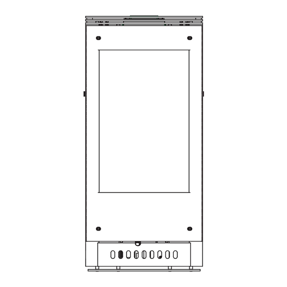
Reference Materials A. Appliance Dimension Diagram Without Stone Surround Dimensions are actual appliance dimensions. Use for reference only. For framing dimensions and clearances refer to Section 3. Height includes 3/8 in (9.53 mm) hearth pad Location Figure 12.1 Appliance Dimensions Hearth Pad Inches Millimeter... -
Page 53: Appliance Dimension Diagram With Stone Surround
B. Appliance Dimension Diagram With Stone Surround Hearth Pad Location Figure 12.2 Appliance Dimensions with Stone Surround Height includes 3/8 in (9.53 mm) hearth pad Height includes 3/8 in (9.53 mm) hearth pad Inches Millimeter Location 29-5/8 24-3/8 30-1/4 3-1/4 Heat &... -
Page 54: Vent Components Diagram
C. Vent Components Diagram 9-7/16 in. 240 mm 6-5/8 in. 168 mm 7-1/4 in. 184 mm 6-9/16 in. 167 mm SLP6A 6-5/8 in. 168 mm 13-1/4 in. 337 mm 6-9/16 in. 167 mm SLP12 Note: Pipes overlap 1-3/8 inches (34.93 mm) at each joint. Figure 12.3 SLP Series Vent Components 6-9/16 in. -
Page 55: Vent Components List
D. Vent Components List COMPONENTS SLP-WT-BK Ceiling Support / Wall Thimble, Black SLP-CCS-BK Cathedral Ceiling Support, Black SLP6-BK 6 inch Pipe Length, Black SLP4-BK 9 inch Pipe Length, Black SLP12-BK 12 inch Pipe Length, Black SLP34-BK 24 inch Pipe Length, Black SLP36-BK 36 inch Pipe Length, Black SLP48-BK... -
Page 56: Service Parts
PALOMA E. Service Parts Service Parts Diagram Beginning Manufacturing Date: July 2005 Ending Manufacturing Date: ______ Log Set Assembly Part number list on following page. Heat & Glo • Paloma • 7031-220 Rev. P • 10/08... -
Page 57: Service Parts List
E. Service Parts List IMPORTANT: THIS IS DATED INFORMATION. When requesting service or replacement parts for your appliance please provide model number and serial number. All parts listed in this manual may be ordered from an authorized dealer. ITEM DESCRIPTION Log Set Assembly Removable Top Assembly Top Vent Removable Top Assembly Rear Vent... - Page 58 E. Service Parts List IMPORTANT: THIS IS DATED INFORMATION. When requesting service or replacement parts for your appliance please provide model number and serial number. All parts listed in this manual may be ordered from an authorized dealer. ITEM DESCRIPTION Temp Sensor Switch On/Off rocker Variable Speed Control...
- Page 59 E. Service Parts Valve Diagram Bottom Plate Assembly IMPORTANT: THIS IS DATED INFORMATION. When requesting service or replacement parts for your appliance please provide model number and serial number. All parts listed in this manual may be ordered from an authorized dealer. ITEM DESCRIPTION Burner Assembly, Hybrid...
-
Page 60: Limited Lifetime Warranty
F. Limited Lifetime Warranty Hearth & Home Technologies LIMITED WARRANTY Hearth & Home Technologies (“HHT”) and its respective brands extends the following warranty for HHT gas, wood, pellet and electric appliances purchased from an authorized HHT dealer and installed in the United States of America or Canada. Warranty starts with date of purchase by the original owner (End User) except as noted for replacement parts. - Page 61 F. Limited Lifetime Warranty (continued) • This limited warranty does not extend to or include surface fi nish on the appliance or terminations, door gasketing, glass gasketing, glass discoloration, fi rebrick, pellet logs, kaowool or other ceramic insulating materials. Rust and/or corrosion on any of the metal surfaces, cast iron components, baffl...
-
Page 62: Contact Information
G. Contact Information Please contact your Heat & Glo dealer with any questions or concerns. ________________________________________________________________________________ ________________________________________________________________________________ ________________________________________________________________________________ ________________________________________________________________________________ ________________________________________________________________________________ ________________________________________________________________________________ ________________________________________________________________________________ ________________________________________________________________________________ ________________________________________________________________________________ • Important operating a n d m a i n t e n a n c e instructions included.
Need help?
Do you have a question about the PALOMA-BL and is the answer not in the manual?
Questions and answers