
Related Manuals for Kramer VS-41H


Summary of Contents for Kramer VS-41H
-
Page 1: User Manual
KR AMER ELECTRON ICS LT D. USER MANUAL MODEL: VS-41H 4x1 HDMI Switcher P/N: 2900-000667 Rev 3... -
Page 3: Table Of Contents
Default Communication Parameters Protocol 2000 Figures Figure 1: VS-41H 4x1 HDMI Switcher Front Panel Figure 2: VS-41H 4x1 HDMI Switcher Rear Panel Figure 3: Connecting the VS-41H 4x1 HDMI Switcher Figure 4: Local Area Connection Properties Window ... -
Page 4: Introduction
Scan Converters and Scalers; GROUP 8: Cables and Connectors; GROUP 9: Room Connectivity; GROUP 10: Accessories and Rack Adapters and GROUP 11: Sierra Products. Congratulations on purchasing your Kramer VS-41H 4x1 HDMI Switcher, which is ideal for the following typical applications: •... -
Page 5: Getting Started
Do not secure the cables in tight bundles or roll the slack into tight coils • Avoid interference from neighboring electrical appliances that may adversely influence signal quality • Position your Kramer VS-41H away from moisture, excessive sunlight and dust VS-41H - Getting Started... -
Page 6: Overview
Overview The VS-41H is a high-performance switcher for HDMI signals. It reclocks and equalizes the signal and switches one of the 4 inputs to a single HDMI output. In particular, the VS-41H features: • A maximum data rate of 6.75Gbps (2.25Gbps per graphic channel) •... -
Page 7: Defining Edid
(that is connected to the display’s source). The EDID enables the VS-41H to “know” what kind of monitor is connected to the output. The EDID includes the manufacturer’s name, the product type, the timing data supported by the display, the display size, luminance data and (for digital displays only) the pixel mapping data. -
Page 8: About Hdcp-General Description
To protect copyright holders (such as movie studios) from having their programs copied and shared, the HDCP standard provides for the secure and encrypted transmission of digital signals. Defining the VS-41H 4x1 HDMI Switcher This section defines the VS-41H. VS-41H - Overview... -
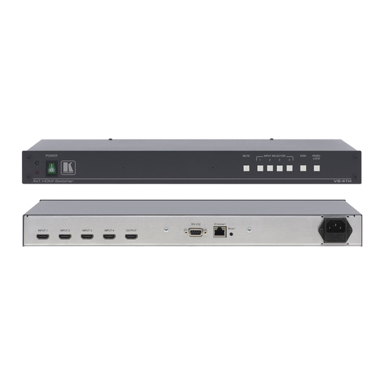
Page 9: Figure 1: Vs-41H 4X1 Hdmi Switcher Front Panel
Figure 1: VS-41H 4x1 HDMI Switcher Front Panel Feature Function IR Receiver LED illuminates when receiving signals from the infrared remote control transmitter POWER Switch Illuminated switch for turning the unit ON or OFF MUTE Button Press to toggle disconnecting the output... -
Page 10: Figure 2: Vs-41H 4X1 Hdmi Switcher Rear Panel
Figure 2: VS-41H 4x1 HDMI Switcher Rear Panel Feature Function INPUT HDMI Connectors Connect to the HDMI sources (from 1 to 4) OUTPUT HDMI Connector Connects to the HDMI acceptor RS-232 9-pin D-sub Connector Connects to a PC or an RS-232 remote controller... -
Page 11: Installing In A Rack
Installing in a Rack This section provides instructions for rack mounting the unit. VS-41H - Installing in a Rack... -
Page 12: Connecting The Vs-41H
Connecting the VS-41H Always switch off the power to each device before connecting it to your VS-41H. After connecting your VS-41H, connect its power and then switch on the power to each device. To connect the VS-41H 4x1 HDMI Switcher (as illustrated in... -
Page 13: Figure 3: Connecting The Vs-41H 4X1 Hdmi Switcher
Figure 3: Connecting the VS-41H 4x1 HDMI Switcher VS-41H - Connecting the VS-41H... -
Page 14: Operating The Vs-41H
Section 6.4) The PC and DVD Modes The VS-41H has two operation modes that can be set individually for each input: the PC mode (default) and the DVD mode: • Use the PC mode when connecting one or more computers to the inputs using a DVI-to-HDMI converter cable For example, the Kramer HDMI-DVI gold-plated cable in various lengths (3”, 6”, 10”... -
Page 15: Setting The Edid
Section 6.2.2). 6.2.1 Acquiring / Changing the EDID You can work with the default EDID or acquire or change an EDID via the connected output. Use the EDID button to acquire the output EDID information. VS-41H - Operating the VS-41H... -
Page 16: Connecting Via The Rs-232 Port
Connecting the ETHERNET Port directly to a PC (Crossover Cable) You can connect the Ethernet port of the VS-41H to the Ethernet port on your PC, via a crossover cable with RJ-45 connectors. This type of connection is recommended for identification of the factory default IP Address of the VS-41H during the initial configuration. -
Page 17: Figure 4: Local Area Connection Properties Window
5. Select the Internet Protocol (TCP/IP) and click the Properties Button (see Figure Figure 4: Local Area Connection Properties Window 6. Select Use the following IP Address, and fill in the details as shown in Figure 7. Click OK. VS-41H - Operating the VS-41H... -
Page 18: Figure 5: Internet Protocol (Tcp/Ip) Properties Window
Connecting the ETHERNET Port via a Network Hub (Straight- Through Cable) You can connect the Ethernet port of the VS-41H to the Ethernet port on a network hub or network router, via a straight through cable with RJ-45 connectors. 6.4.3... -
Page 19: Technical Specifications
10% to 90%, RHL non-condensing DIMENSIONS: 19” x 7” x 1U (W, D, H) WEIGHT: 2.5kg (5.5lbs) approx. ACCESSORIES: Power cord, rack “ears” and IR remote control Specifications are subject to change without notice at http://www.kramerelectronics.com VS-41H - Technical Specifications... -
Page 20: Default Communication Parameters
Baud Rate: 9600 Data Bits: Stop Bits: Parity: None Command Format: Example (Output 1 to Input 1): 0x01, 0x81, 0x81, 0x81 Ethernet IP Address: 192.168.1.39 TCP Port Number: 5000 Network Mask: 255.255.255.0 Default Gateway: 192.168.1.1 VS-41H - Default Communication Parameters... -
Page 21: Protocol 2000
Protocol 2000 Kramer Protocol 2000 for RS-232/RS-485 communication uses four bytes of information as defined below. DESTINATION INSTRUCTION 1st byte INPUT 2nd byte OUTPUT 3rd byte MACHINE NUMBER 4th byte 1st BYTE: Bit 7 – Defined as 0. D – “DESTINATION”: 0 - for sending information to the switchers (from the PC);... - Page 22 OUTPUT is assigned the value of the requested parameter. The replies to instructions 10 and 11 are as per the definitions in instructions 7 and 8 respectively. For example, if the present status of machine number 5 is breakaway setting, then the reply to the HEX code would be HEX codes VS-41H - Protocol 2000...
- Page 23 (in real-time). For example, if input 3 is detected as invalid, the unit will send the HEX codes If input 7 is detected as valid, then the unit will send HEX codes VS-41H - Protocol 2000...
- Page 25 For the latest information on our products and a list of Kramer distributors, visit our Web site where updates to this user manual may be found. We welcome your questions, comments, and feedback. Web site: www.kramerelectronics.com E-mail: info@kramerel.com SAFETY WARNING...
Need help?
Do you have a question about the VS-41H and is the answer not in the manual?
Questions and answers