Table of Contents
Advertisement
Quick Links
the
Great Outdoors
Assembly and Owner's Manual
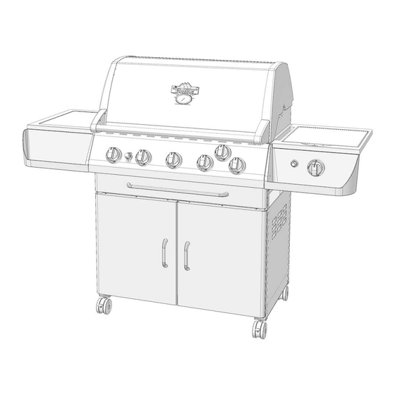
TG560
Portable
Gas Grill
ASSEMBLER / INSTALLER:
Leave these instructions with the consumer.
CONSUMER / USER:
Read all of these instructions and keep them in a safe place for future reference.
FOR YOUR SAFETY
If you smell gas:
1
Shut off gas to the appliance.
2
Extinguish any open flame.
3
Open lid.
4
If odor continues, immediately call
your gas supplier or fire department.
FOR YOUR SAFETY: Never leave a grill unattended when in use.
L.P. Gas
Cylinder
Not Included
FOR YOUR SAFETY
1
Do not store or use gasoline or other
flammable vapors and liquids in the
vicinity of this or any other appliance.
2
An unconnected liquid propane
cylinder should not be stored in the
vicinity of this or any other appliance.
TM
Advertisement
Table of Contents

Related Manuals for CFM TG560


Summary of Contents for CFM TG560
- Page 1 Great Outdoors Assembly and Owner’s Manual TG560 Portable Gas Grill L.P. Gas Cylinder ASSEMBLER / INSTALLER: Not Included Leave these instructions with the consumer. CONSUMER / USER: Read all of these instructions and keep them in a safe place for future reference.
-
Page 2: Table Of Contents
Connecting to Natural Gas ..... . . 23-24 Formerly: ® Now: CFM Corporation 2695 Meadowvale Boulevard Mississauga, Ontario L5N 8A3 Canada (800) 668-5323 www.cfmcorp.com Service Note: If you are experiencing difficulties or are dissatisfied with your purchase, please contact CFM at the telephone number listed above prior to returning your grill to the store. -
Page 3: Chapte R 1 - Installation
Pinnacle Series Gas Grill Installation Chapter Necessary Information to · Operating this or any gas-fired appliance in an enclosed area can produce a build-up Safely Use a Gas Grill of carbon-monoxide, which could result in injury or death. 2. Installation must conform with local The gas fuel used by this product is codes or, in the absence of local codes, with... -
Page 4: Portable L.p. Gas Grills
9. Make sure that the drip pan is in place under the grill bottom. · Hot drippings from cooking food could damage the fuel supply system. IMPORTANT: NEVER leave a grill unattended when in use. Portable L.P. Gas Barbecue Grills WARNING: Do not use natural gas in an appliance designed for L.P. - Page 5 4. The pressure regulator and hose assembly provided is factory set at an outlet Multiple Burner pressure of 11 inches water column (.4 lb. Fuel-Control Valves per sq. Inch). Sideburner WARNING: Any attempt to adjust the Valve regulator is dangerous and could create a situation causing personal injury or property Fuel Supply damage.
- Page 6 The L.P. gas cylinder must have a shut-off Have the gas dealer weigh the cylinder valve terminating in a Type 1 L.P. gas- after filling to ensure that the cylinder is not cylinder-valve outlet. A Type 1 compatible overfilled. cylinder with a Type 1 cylinder valve has a positive seating connection that does not DANGER: permit gas flow until a positive seal has been...
-
Page 7: Gas Dealer Instructions
Take These Instructions to the L.P. Gas Dealer When using a cylinder exchange, be sure The L.P. gas cylinder has a Type 1 cylinder the exchanged cylinder is a Type 1 cylinder; valve with a back-check module in its outlet a 510 POL cylinder will not fit a Type 1 that will not permit gas to flow until an regulator. -
Page 8: Chapter 2 - Assembly Instructions
Pinnacle Series Gas Grill Assembly Instructions Chapter Unpacking the Grill Parts Getting Started A box knife may be necessary to open 1. Please follow the steps in the order that cartons and bags. they are presented. 2. Remove and set aside all inner boxes 2. - Page 9 HARDWARE: M5x10mm Screw M6x15mm Bolt M6x40mm Bolt 1/4-20 Thumb M6 Nut Screw Figure A: (L.P. Gas Models Only) Step 1: Attach the drawer slides (58) to the tank holder (57) using four M5 screws (A) as shown. Ensure that the ends of the drawer slides are flush with the front of the tank holder.
- Page 10 HARDWARE: Snap Bushing M6x15mm Bolt M6x40mm Bolt M6 Nut Figure C Figure C: Step 9 Step 8: Attach the back panel (54) to the back of the cart assembly as shown. Use two M6x15mm bolts (B) to secure the top, and two M6x40mm bolts (C) to secure the bottom as shown.
- Page 11 HARDWARE: Figure E M3.5x6mm Screw M3.5 Nut M6x15mm Bolt Figure E: Step 13: Attach the outer drawer tracks (61 & 62) to the support brackets (50) as shown using M3.5 screws (G) Left and M3.5 nuts (H). Securely tighten the screws. The support brackets are not specific to left or right.
- Page 12 HARDWARE: Figure G M3.5x6mm Screw M3.5 Nut M4x6mm Screw Figure G: Step 15: Insert the four casters (65 & 68) into the bottom of the leg posts as shown. The two locking casters (65) go in the front, the two non-locking casters (68) go in back.
- Page 13 Figure K2 HARDWARE: Nylon Figure K Washer Figure K: Left Step 19: Place the nylon washers (K) onto the lower door mounts (52 & 55). Step 20: Mount the doors (53 & 56) to the lower door mounts (52 & 55). The holes in the doors slide over the lower door mount hinges (see Figure K1).
- Page 14 Figure N1 HARDWARE: M5x10mm Bolt Figure N Figure N2 Figure N: Step 23: Set the grill head (21) onto the cart assembly. Caution: the grill head is heavy - be sure to get assistance. Step 24: Before securing the grill head, route the gas hose though the cut-out portion of the mounting bracket (50) as shown in Figures M1 and M2.
- Page 15 Figure P: Figure P Step 26: Remove the four screws (B) from the left side table (28) indicated as shown. Do not discard the screws - they will be used in the next step. Figure Q: Step 27: Mount the left side table bracket (30) to the left side table (28) as shown, using two of the screws previously...
- Page 16 Figure S1, S2 & S3: Step 30: Remove the two screws (A) from the side burner valve (b) indicated as shown. Do not discard the screws - they will be used in the next step. Step 31: Attach the side burner valve (b) and knob bezel (25) to the right side condiment tray (32) as shown.
- Page 17 Figure U: Step 33: Mount the right side table bracket (33) to the side burner table (31) as shown above, using two of the screws previously removed in step 30. Securely tighten the screws. Step 34: Mount the right side condiment tray (32) to the side burner table (31) as shown above.
- Page 18 Figure X Figure X: Step 37: On the side of the grill tub, locate the four bolts indicated by the arrows shown. For bolts marked as "A", loosen them about half way and leave them threaded into the grill tub. For the bolt marked as "B", remove it and set it aside.
- Page 19 Figure Z: Insert the heat Step 39: five shields into the grill tub. (24) Each heat shield must be placed above a burner, resting on the brackets in the front and rear of the grill tub. Place the cooking grid Step 40: s (27) onto the top of the grill tub.
- Page 20 Figure CC: Step 43: Place the drip cup (20) into the drip cup holder (19). Step 44: Hang the drip cup holder (19) from the grease pan (46) drain hole underneath the grill tub, inside the cabinet. The warming drawer may need to be pulled out to access the area.
-
Page 21: Installing An L.p. Gas Cylinder
Connecting the L.P. Gas Cylinder Connecting the Regulator to Cylinder 1. The top knob on the supply cylinder must about one-half to three-quarters additional be closed. See that the top cylinder knob is turn to complete the connection. turned clockwise to a full stop. NOTE: If you cannot complete the final 2. -
Page 22: Connecting To Natural Gas
Natural Gas Grills - Connecting to Natural Gas (for specially equipped natural gas grills only) DANGER: EXPLOSIVE AND FLAMMABLE! If A quick-connect coupling sleeve with 3/8” the appliance is for connection to natural gas, female end is provided. Install the connector the gas connections should be made by a socket at the pipe end, after the shut-off qualified installer or a licensed plumber. - Page 23 Natural Gas Grills - Connecting to Natural Gas (for specially equipped natural gas grills only) OPERATING THE QUICK-CONNECT 5. Push the plug into the connector until the sleeve snaps forward to lock the fitting in place. Follow all directions on tags attached to hose. Turn on the shut-off valve.
-
Page 24: Side Burner Operation
Side Burner Operation OPERATING THE SIDE BURNER Before operating the side burner, you must first open the burner cover. (A) After using the side burner, wait until the unit is completely cool before closing the burner cover. IGNITING THE SIDE BURNER (Read all the steps before beginning.) STEP 1. - Page 25 Rotisserie Burner Operation The Rotisserie burner provides the steady, STEP 5. Immediately press the igniter button. even heat required to cook poultry and roasts to You will hear rapid clicks. Repeat if necessary. self-basted perfection. Always preheat the Grill before starting to cook on the rotisserie. The rotisserie burner should light within 3-5 seconds.
- Page 26 Model TG560 Replacement Parts Replacement parts are available direct from our For warranty replacements, proof of ownership and warehouse. Some components are not available replacement parts and shipping may apply. preassembled and may be ordered separately. For For warranty replacements, proof of ownership and date convenience, the following parts list is provided along of purchase is required.
- Page 27 Hardware - As in the plastic bag The following shows the contents of the hardware bag found with your grill. The letters beside each of the fasteners corresponds to the letters used in the assembly manual. The components are shown as actual size.
Need help?
Do you have a question about the TG560 and is the answer not in the manual?
Questions and answers