Advertisement
Quick Links
This Owner's Manual is provided and hosted by Appliance Factory Parts.
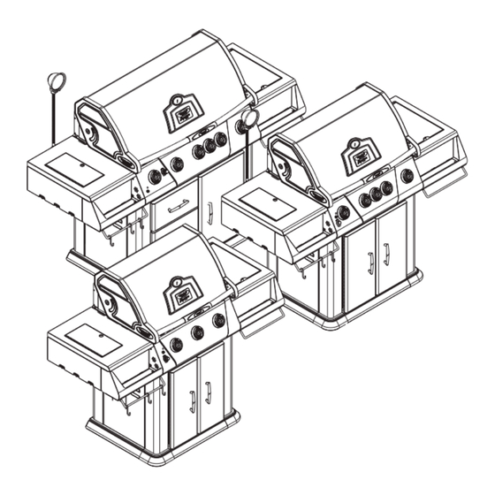
Vermont Castings VCS3008
Owner's Manual
Shop genuine replacement parts for Vermont Castings
VCS3008
Find Your Vermont Castings Grill Parts - Select From 273 Models
-------- Manual continues below --------
Advertisement

Related Manuals for CFM Vermont Castings Signature VCS3008 Series


Summary of Contents for CFM Vermont Castings Signature VCS3008 Series
- Page 1 This Owner's Manual is provided and hosted by Appliance Factory Parts. Vermont Castings VCS3008 Owner's Manual Shop genuine replacement parts for Vermont Castings VCS3008 Find Your Vermont Castings Grill Parts - Select From 273 Models -------- Manual continues below --------...
- Page 2 Assembly Procedures VCS3008 Series / VCS4008 Series / VCS5008 Series Tools Required: Knife or scissors, Phillips or Robertson (square head) screwdriver, 7/16” and 3/8” wrench or ratchet. The use of a manual screwdriver is strongly recommended. A power drill may cause damage to the unit or stripping of the protective coating.
- Page 3 VCS3008/4008/5008 Series Assembly Step 1: Unpack Carton and Verify Contents Use a sharp cutting tool to cut the straps on the packaging and then lift off the carton top. Remove the box on the top. The sleeve surrounding the barbecue can be removed by lifting it straight up and over the top of the unit.
- Page 4 VCS3008/4008/5008 Series Assembly Step 1: Unpack Carton and Verify Contents (continued) VCS4008 VCS4008 Series Carton Contents Box 1 (50004562) Grease Pan Cabinet Skirt Front Assy Cabinet Skirt Assy Left Cabinet Skirt Assy Right Cabinet Skirt Corner Assy (2) Hardware Bag Casters/Skirt Knob Long Stem (4) Knob (2) Adjustable Leveling Glide (Set of 4)
- Page 5 VCS3008/4008/5008 Series Assembly Step 1: Unpack Carton and Verify Contents (continued) VCS5008 Series Carton Contents Box 1 (50004551) Grease Pan Cabinet Skirt Front Assy Cabinet Skirt Assy Left Cabinet Skirt Assy Right Box 4 (50004557) Cabinet Skirt Corner Assy (2) Heat Plate (5) Hardware Bag Casters/Skirt Box 7 (50004992) LP Model...
- Page 6 VCS3008/4008/5008 Series Assembly Step 2: Install the Casters This step requires 2 people. Parts Required: (4) Casters (2 with brake, rear; 2 without brake, front) (1) Block (not included) (16) 1/4-20 Flange Nut (50001176) Figure 1 NOTE: Casters (wheels) may differ from those shown in the illustration depending on the model you pur- chased.
- Page 7 VCS3008/4008/5008 Series Assembly Step 3: Attach Skirt Figure 2 Parts Required: Leveling (1) Skirt Left Assembly Glide (1) Skirt Right Assembly (1) Skirt Front Assembly (2) Skirt Corner Assemblies Skirt Right Assembly (7) #10-24 x 3/8” Screws (50004268) Skirt Left Assembly (4) Adjustable Leveling Glide Figures 2 &...
- Page 8 VCS3008/4008/5008 Series Assembly Step 4: Attach Grease Cup Holder Figure 4 (VCS3008, VCS4008 Series Only) Parts Required: (1) Grease Cup Holder (2) #10-24 x 1/2” Screws (50000337) #10-24 x 1/2” Figure 4 Screws (50000337) Attach grease cup holder to the bottom of the left brace support.
- Page 9 VCS3008/4008/5008 Series Assembly Parts Required for Steps 6, 7, 8 & 9 Right Side Shelf Left Side Shelf (1) Kit Condiment Tray* (50004547) (1) Kit Condiment Tray* (50004547) (1) Kit Shelf Right** (50004572) (1) Kit Shelf Left*** (50004571) *Kit Condiment Tray (50004547) Contents (1) Condiment Tray Left (1) Condiment Tray Right (2) Towel Bars...
- Page 10 VCS3008/4008/5008 Series Assembly Steps 6 & 7: Right & Left Side Shelf Assembly Parts Required: (1) Kit Condiment Tray (50004547) (1) Condiment Tray Left (1) Condiment Tray Right (1) Kit Shelf Right (50004572) (1) Shelf Right Assy w/Support Brackets (1) Hardware Bag (for both right and left side shelves) (1) Kit Shelf Left (50004571) (1) Shelf Left Assy.
- Page 11 VCS3008/4008/5008 Series Assembly Step 8: Attach Right Shelf Assembly to Grill Parts Required: Right Shelf Assembly (1) Right Shelf Assy. (Step 6) (4) 1/4-20 x 1¹⁄₂” Screws (50001383) (2) #10-24 x 1/2” Screws (50000337) Figures 8 & 9 Loosely screw in (4-5 turns) four (4) 1/4-20 x 1¹⁄₂” screws to the side of the grill. Place right shelf assembly onto screws.
- Page 12 VCS3008/4008/5008 Series Assembly Step 9: Attach Left Shelf Assembly to Grill Parts Required: Left Shelf Assembly Figure 10 (1) Left Shelf Assy. (Step 7) (4) 1/4-20 x 1¹⁄₂” Screws (50001383) (4) #10-24 x 1/2” Screws (50000337) Heat Shield Marinating (1) Marinating Station Tray Tray (1) Heat Shield Marinating Tray (2) #10-24 K-lock Nut (50000182)
- Page 13 VCS3008/4008/5008 Series Assembly Step 10: Attach Knobs Parts Required: VCS3008 Series: (3) Knobs (long stem) VCS4008 Series: (5) Knobs (3 long stem, 2 short stem) VCS5008 Series: (6) Knobs (4 long stem, 2 short stem) Figures 12 & 13 Align the knobs on the valve stems and push inward until the knob sits snugly on the stem. NOTE: Place the long stem knobs in the center raised portion of the console.
- Page 14 VCS3008/4008/5008 Series Assembly Step 11: Attach Towel Bars, Utensil Hooks and Spit Rod Storage Brackets Parts Required Left Side Right Side (1) Towel Bar (1) Towel Bar (3) Utensil Hooks (4) #10-24 x 1/2” Screws (50000337) (4) #10-24 x 1/2” Screws (50000337) Spit Rod Storage Bracket (2) Brackets (50004310) Towel Bars and Utensil Hooks...
- Page 15 VCS3008/4008/5008 Series Assembly Step 12: Attach Side Burner Assembly Follow Side Burner Assembly Instructions to assemble side burner to unit. Step 13: Install the Ignitor Battery Figure 16 NOTE: VCS3008 Series require one (1) “AAA” battery. (Included) VCS4008 and VCS5008 Series require one (1) “AA”...
- Page 16 VCS3008/4008/5008 Series Assembly Step 15: Install the Internal Components Parts Required: VCS3008 (3) Sear Plates VCS4008 (4) Sear Plates VCS5008 (5) Sear Plates Series (2) Cooking Grates Series (3) Cooking Grates Series (4) Cooking Grates (1) Warming Rack (1) Warming Rack (1) Warming Rack (1) Smoker Box Assy (1) Smoker Box Assy...
- Page 17 VCS3008/4008/5008 Series Assembly Step 15: Install the Internal Components (continued) Figure 21 Set the cooking grates, side by side, on the upper ledge of the grill tub. (Fig. 21) Make sure the finger groove is facing toward the front of the grill. Warming Rack Set the warming rack into the supports located on either Cooking...
- Page 18 VCS3008/4008/5008 Series Assembly Step 17: Install LP Tank Pull Out Assembly For VCS4008 & VCS5008 Series Models only. Follow Tank Pull Out Assembly instructions to assemble. NOTE: For VCS5008 Series, replace pull out drawers now. Step 18: Install the LP Cylinder (LP Models ONLY) Parts Required: (1) LP Gas Cylinder (not included)
- Page 19 VCS3008/4008/5008 Series Assembly Step 19: Install the Natural Gas Hose (Natural Gas (NG) Models ONLY) Figure 25 Run natural gas hose through bushing provided in back panel of grill. Figure 25 B240 ���� ������� ��� ���� ����� CAUTION: Some parts may have sharp edges; to avoid injury, wearing gloves during assembly, lifting or moving the grill is recommended.
- Page 20 VCS3008/4008/5008 Series Assembly Step 20: Install Shelf Light (VCS4008, VCS5008 Series Only) Parts Required: (1) Cook Light Figure 26 (3) #10-24 x 1/2” Screws (50000337) Figures 26 , 27 & 28 Attach the cook light to the side shelf using three (3) screws provided. (Fig.
- Page 21 VCS3008/4008/5008 Series Assembly CFM Corporation 2695 Meadowvale Blvd. • Mississauga, Ontario, Canada L5N 8A3 800-668-5323 • www.cfmcorp.com CAUTION: Some parts may have sharp edges; to avoid injury, wearing gloves during assembly, lifting or moving the grill is recommended. 50004582...
Need help?
Do you have a question about the Vermont Castings Signature VCS3008 Series and is the answer not in the manual?
Questions and answers