Table of Contents
Advertisement
Quick Links
Advertisement
Table of Contents

Related Manuals for Coda C25


Summary of Contents for Coda C25
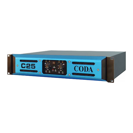
- Page 1 Coda Audio C25 Power Amplifier User Guide version 1.0...
-
Page 2: Table Of Contents
Operation Switching on Panel Controls and Indicators Level controls Bar Signal indicators -3dB indicator Limiters PRC indicators Temperature control Fault indicators Bridged LED Maintenance Technical Specification Power requirements Appendix Table of PRC settings and resulting C25 User Guide Version 1.0... -
Page 3: Ec Declaration Of Conformity
C25 User Guide Version 1.0... -
Page 4: Important Safety Instructions
120 V Areas: Earth: = Green Neutral: = Blue Neutral: = White Live: = Brown Live: = Black Warning: To reduce the risk of fire or electric shock, do not expose this apparatus to rain or moisture. C25 User Guide Version 1.0... -
Page 5: Mechanical
RF radiation, such as radio microphone receivers. Features: The C-Series introduces three user-controlled features previously not seen on Coda Audio amplifiers: -3 dB indicators Power reduction control (PRC) ... -
Page 6: Db Indicators
Introduction The C25 are no compromise, high quality, class AB power amplifiers. There is no dynamic switching of the audio or power rails, thus ensuring optimum sonic performance. Fan speed is varied as required to keep the amplifier within its temperature limits. Signal limiters are included to protect speakers from clipped signals. -
Page 7: Connections
C25 - 16A all into 4 Ohm speaker loads Note: Do not connect the inputs/outputs to any other voltage source such as a battery, mains source or power supply, regardless of whether the amplifier is turned on or off. -
Page 8: Bridged Operation
In the event of excessive temperature, the protection circuit will operate, disabling the output. The red ‘AUDIO-PROTECT’ (A/P) LED will indicate this condition. (See fault indicator.) The C25 has four fans connected permanently with variable speed and a jumper link to enable them from cold. -
Page 9: Fault Indicators
(ENSURE THAT ELECTRICAL POWER TO THE UNIT IS DISCONNECTED BEFORE CARRYING OUT ANY MAINTENANCE.) The filter behind the air intake apertures on the front of C25 should be cleaned or replaced periodically, e.g. 6-12 months. (Filters in amplifiers located in more 'dirty' atmospheres may require more frequent maintenance.) The filters can be removed and replaced without removing the blue... -
Page 10: Technical Specification
Power requirements The C25 can be supplied for nominal mains voltage of 115 V or 230 V. An internal link can be set to either 100 V or 120 V for the 115 V version and 220 V or 24 0V for the 230 V version. -
Page 11: Appendix
2500 -2 dBu PRC Setting 1600 -4 dBu PRC Setting 1050 -6 dBu PRC Setting Max Power into 2 Ohm 2200 -2 dBu PRC Setting 1400 -4 dBu PRC Setting 1000 -6 dBu PRC Setting C25 User Guide Version 1.0... - Page 12 Coda Audio GmbH Boulvard der EU 6 30539 Hannover Germany Phone: +49 (0) 511 – 866 55 888 Fax: +49 (0) 511 – 866 55 887 E-Mail: contact@codaaudio.com Website: www.codaaudio.com...
Need help?
Do you have a question about the C25 and is the answer not in the manual?
Questions and answers