Table of Contents
Advertisement
Quick Links
Advertisement
Table of Contents

Related Manuals for Coda C5


Summary of Contents for Coda C5
- Page 1 Coda Audio C5 DSP amplifier User Guide version 1...
-
Page 2: Important Safety Information
Important Safety Information Please read carefully and keep the following instructions and safety information. Heed all warnings and follow all instructions. Do not remove covers. There are no user serviceable parts inside; please refer servicing to qualified service personnel. This equipment must be earthed. Protect the power cord from being walked on or pinched, particularly at plugs, convenience receptacles and the point where they exit from the apparatus. -
Page 3: Table Of Contents
Table of Contents Important Safety Information ....................2 Regulatory Compliance ....................2 Thanks and Unpacking ......................5 Introduction and Key Features ....................6 Front Panel .......................... 13 Power Switch ........................ 13 Power ON indicator ......................13 Bridged Mode indicator ....................13 Control Software Online indicator .................. - Page 4 EQ and Filter Response Graphs ....................27 Signal Processing Block Diagram ..................30 Technical Specifications ..................... 31...
-
Page 5: Thanks And Unpacking
Thanks and Unpacking Thank you for choosing a Coda Audio C5 DSP amplifier system for your application. Please spare a little time to study the contents of this manual, so that you obtain the best possible performance from this unit. -
Page 6: Introduction And Key Features
Introduction and Key Features Introduction The C5 DSP amplifier systems from Coda Audio integrate light-weight power supplies, high power sonically transparent class D amplifiers, complete system monitoring and a fully featured USB or network controlled 24 bit 96kHz DSP processing platform as standard. -
Page 7: Mechanical Installation
Mechanical Installation The C5 DSP amplifier system is designed to be mounted in a standard 19” rack enclosure. Where the amplifier is used in a fixed installation, it is possible to use only the front panel 19” rack mounting holes to mount it in a standard rack enclosure. If the amplifier is... - Page 8 It is possible to mount multiple C5 amplifiers without ventilation gaps between them but it is essential that an unobstructed flow of clean air is available from the back of the unit to the front.
-
Page 9: Ac Power Connection
The C5 amplifiers are designed to operate on 50/60 Hz AC power. The power supply sections automatically configure themselves for either 115V or 230V nominal voltage at turn on. The amplifiers will operate over an extended range of supply voltages from;... -
Page 10: Audio Connections
Audio Connections For each amplifier channel there are female and male XLR input connectors which are wired in parallel. Typically the female connector is used for the audio input, the male XLR connector being available to link the same audio signal to another amplifier channel. The HOT, + or „in phase‟... -
Page 11: Using Unbalanced Connections
Using unbalanced connections When connecting the C5 amplifier to an unbalanced audio source, the signal conductor should be terminated to XLR pin2 and the cable screen terminated to both pins 1 and 3. Input XLR unbalanced connection Pin 2 HOT + Pin 1 Shield In bridged mode output channel 1 signal chain provides the signal for the 1 &... -
Page 12: 100V Line Operation
4 ohms. 100V line operation A single channel of an C5 can deliver 1250W in to 2 Ohms, therefore the RMS voltage at the speaker terminals when delivering this will be √(1,250 x2) = 50V. -
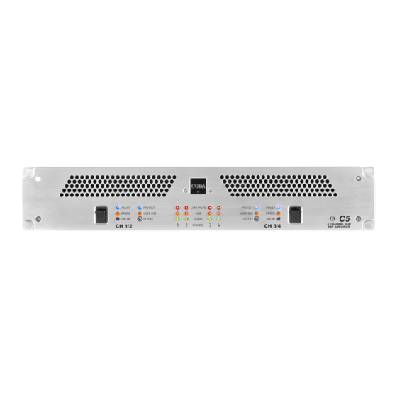
Page 13: Front Panel
Front Panel Power Switch The C5 amplifier is fitted with either one or two dual channel power modules. As the power modules operate independently there is a separate power switch for each. When the power switch is operated, the protect indicator will flash while the DSP and amplifier control systems are prepared. -
Page 14: Protect
Protect The C5 DSP amplifier system has sophisticated protection and monitoring systems which keep the amplifier within its safe operating window whenever possible. This indicator lights when the protection systems are active in any way. User DSP indicator Using the C-Net PC application the user can introduce audio processing such as EQ, gain and delay. -
Page 15: Rear Panel
Power Inlet The C5 amplifier should be connected to a suitable mains electricity supply using the cable supplied. The unit uses auto ranging switch mode power supplies which are capable of operating with a nominal mains voltage of either 115V or 230V, 50/60Hz without re- configuration. -
Page 16: Communications Port Connections
When using the C-Net sockets, you will need to use a C-Net Interface accessory to allow your computer to communicate with the C-Net network. Before connecting a USB port from your computer to either the USB socket on C5, or to a first... -
Page 17: C-Net Amplifier Control Panel
Voice is indicated on the C-Net panel. The Aux Out socket allows you to chain the Aux connections on to further C5 so that the same voice selection is done on all of them. There is no practical limit to the number of C5 that may be chained together via the Aux sockets. -
Page 18: Amplifier Channels
This section of the user guide explains the functions of the C-Net control panel for the C5 DSP amplifiers. For further help and information on the main C-Net application please click on the help button on the main application. For more detailed help about the C5 control panel, click the “?”... -
Page 19: Monitoring Section (Monicon)
When the User DSP indicator is off, the amplifier is in Factory voice. In the Factory voice, you cannot change any of the settings; they are fixed by Coda Audio (and thus are a safe „fallback‟ if something goes wrong with your settings). Only when the indicator is on will changes you make in C-Net be heard. -
Page 20: Main Control Panel
The Output section allows you to control the output drive level of each amplifier. Also, depending on which parameters have been hidden by Coda Audio, you may also be able Adjust the routing from inputs to outputs (allowing you for example to feed two outputs from one input). - Page 21 (such as “Left Fill”). Also viewable in this tab are the model name of the amplifier, and the name of the settings provided by Coda Audio of the factory file. The Maintenance area shows some details of how the amplifier has been used and the amount of protection the amplifier is applying.
-
Page 22: Hidden Controls
Hidden Controls Coda Audio may have hidden some of the controls on the panel in order to maintain proper protection of the connected loudspeakers. Such hidden controls will appear grey and cannot be adjusted. Saving & Recalling Data Device Data may be saved to disk or opened from disk. C-Net Device Settings files (with file extension .dse) contain all the data necessary to restore a device to exactly the same... -
Page 23: Tool Bar
For further information on loading factory settings, please refer to the C-Net application main help. Tool Bar The toolbar provides the following one-click functions: Open Opens a file which contains parameters for the device. A dialogue will appear, inviting you to choose a file to open. -
Page 24: Audio Processing
PgDown Reduce value (coarsely) Up/Right arrow Increase value (finely) Down/Left arrow Reduce value (finely) On push-button controls: Space Activate Audio Processing The Digital Signal Processor (DSP) within the amplifier does all the necessary processing (such as crossover filtering, driver equalization and power limiting) for the loudspeaker to give you a solution which operates well in most circumstances without the need for further user adjustment (apart from gain). -
Page 25: Equalisation Filters
A 2nd order high-shelf filter with frequency variable over the range 10Hz to 25kHz, and boost/cut from –15 to +15dB, and slope from 6 to 12dB/Octave. Eight bands of parametric equalizer, each band having frequency variable over the range 10Hz to 25kHz, bandwidth variable from 0.18 to 5.6 octaves (Q 0.15 to 8.1), and boost/cut from –15 to +15dB. -
Page 26: Protection
Limiters Coda Audio may have allowed you access to the Limiter threshold settings. These settings require careful adjustment in order to protect your loudspeakers. Please refer to Coda Audio for advice on the appropriate settings to use. Note that a setting of 0dB on the limiters equates to +36.8dBu = 53.8Vrms (or +42.8dBu, 107.7Vrms in bridge mode). -
Page 27: Eq And Filter Response Graphs
EQ and Filter Response Graphs The following plots show the attenuation characteristics of the various crossover filters available within the C5. These are all shown at a crossover frequency of 1kHz. Butt erworth 1 10 1 10 Frequency, Hz 6dB/Oct... - Page 28 Bes sel 1 10 1 10 Frequency, Hz 12dB/Oct 24dB/Oct Hardman 1 10 1 10 Frequency, Hz 4th Order 8th Order...
- Page 29 The following plots show the magnitude response (frequency response) characteristics of the various equalization filters available within the C5. These are all shown at a c frequency of 1kHz. Shelving EQ 1 10 1 10 Frequency, Hz Low shelf, varying Gain...
-
Page 30: Signal Processing Block Diagram
Signal Processing Block Diagram Please note that each C5 contains two of these processing blocks, one for each pair of channels. -
Page 31: Technical Specifications
Technical Specifications AUDIO Input impedance 10k balanced Max Input level +20dBu Frequency Response 20Hz - 20kHz+/-0.5dB @ 4 Ohm load Output noise -106dB A weighted Ref max output, 22kHz BW Distortion <0.05% (1kHz, -3dB output. 22kHz BW) PROTECTION SYSTEMS Output over current Initially gain reduced to maintain control, extreme or persistent over current causes shutdown Over temperature limiters applied, persistent over temperature causes shutdown... - Page 32 Weight 20 pounds, 9 Kgs Operating temperature range 0 to +40°C Relative humidity range 0 to 80% (non-condensing) CONNECTIONS Mains (per C5) Neutrik „Powercon‟ Audio input (per channel) 3 pin female XLR Audio link (per channel) 3 pin male XLR Output (per channel) Neutrik NL4 „Speakon‟...
- Page 33 This product complies with the EMC & LVD directives as issued by the Commission of the European Community. Compliance with these directives implies conformity with the following European standards: EN55103-1 Electromagnetic Interference (Emission) EN55103-2 Electromagnetic Susceptibility (Immunity) EN60065 Electrical safety C5 also meets the requirements of FCC part 15B.
Need help?
Do you have a question about the C5 and is the answer not in the manual?
Questions and answers