Table of Contents
Advertisement
Quick Links
Advertisement
Table of Contents

Related Manuals for Coda C475


Summary of Contents for Coda C475
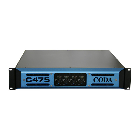
- Page 1 Coda Audio C475 Power Amplifier User Guide version 1.0...
-
Page 2: Table Of Contents
Note that all amplifiers* before serial number 7E70004 have a different wiring configuration for the input and output sockets. This will only affect the “Linked” or “Bridged” modes of operation. * Serial numbering for the C475 commenced with 6E7..C745 User Guide Version 1.0... -
Page 3: Ec Declaration Of Conformity
C475 User Guide Version 1.0... -
Page 4: Important Safety Instructions
Important Safety Instructions Read these instructions. Keep these instructions. Heed all warnings. Follow all instructions. Do not block any ventilation openings and install in accordance with the manufacturer’s instructions. Unplug this apparatus during lightning storms or when unused for long periods of time. Clean only with a dry cloth. -
Page 5: Mechanical
GENERAL INFORMATION Your C475 power amplifier utilises proprietary designed load impedance sensing output circuitry, which enables the amplifier to drive the high voltage swings associated with speaker impedances of 8 ohms and above, but automatically switches to a high current/medium voltage output required by 4 ohm loads. -
Page 6: Power Reduction Circuit (Prc) And Impedance Sensing
Power Reduction Circuit (PRC) and Impedance Sensing There are two PRC circuits in the C475: one for channels A & B and one for channels B & C. When the amplifier is to be used with 4 Ohm speakers (or bridged mono into 8 Ohm) or if you want to reduce the maximum power to protect the speakers, then the PRC can be selected via the switches on the rear panel. -
Page 7: Input Link Switches
+ve = channel D +ve (pin +1 on connector D or +2 on connector C) -ve = channel C –ve (pin -1 on connector C) Note: Both level controls must be set to the same position. When operating in bridged mode, the minimum impedances are 8 Ohm. C475 User Guide Version 1.0... -
Page 8: Operation
C475 14 A into 4 Ohm speaker loads. 3. Do not connect the inputs/outputs to any other voltage source such as a battery, mains source or power supply, regardless of whether the amplifier is turned on or off. -
Page 9: Prc Indicators
In any case, provided that the input signal is less than 20 dBu/7.7 V, the built in limiter circuit will prevent distortion within the amplifier. The gain should be set to match the signal from the source, e.g. mixer, controller, equaliser etc. C475 User Guide Version 1.0... -
Page 10: Air Filter
Air filter The filter behind the air intake apertures on the front of the C475 amplifier should be cleaned or replaced periodically, e.g. 3-6 months. (Filters in amplifiers located in more 'dirty' atmospheres may require more frequent maintenance.) Access is via the blue front panel. The filter should be 'dry' cleaned, using a vacuum cleaner preferably. -
Page 11: Technical Specification
230 V version. Normally these are set to 120 V and 240 V respectively. This amplifier will only operate to its very high specification if it is installed and operated as described in this manual. C475 User Guide Version 1.0... - Page 12 Coda Audio GmbH Boulvard der EU 6 30539 Hannover Germany Phone: +49 (0) 511 – 866 55 888 Fax: +49 (0) 511 – 866 55 887 E-Mail: contact@codaaudio.com Website: www.codaaudio.com...
Need help?
Do you have a question about the C475 and is the answer not in the manual?
Questions and answers