Sign In
Upload
Download
Table of Contents
Contents
Add to my manuals
Delete from my manuals
Share
URL of this page:
HTML Link:
Bookmark this page
Add
Manual will be automatically added to "My Manuals"
Print this page
×
Bookmark added
×
Added to my manuals
Manuals
Brands
SEAL Manuals
Laminator
62C
User manual
SEAL 62C User Manual
Mounter and laminator
Hide thumbs
1
2
3
4
Table Of Contents
5
6
7
8
9
10
11
12
13
14
15
16
17
18
19
20
21
22
23
24
25
26
27
28
29
30
31
32
33
34
35
36
37
38
39
40
41
42
43
44
page
of
44
Go
/
44
Contents
Table of Contents
Troubleshooting
Bookmarks
Table of Contents
Table of Contents
Warranty and Safety Instructions
Safety
Safety Features
Safety Instructions
Warnings
General ESD-Warning
In this Manual
On the Machine
Warranty
Warranty Conditions
Warranty Period
2 Description
General Description
Parts Identification
Process Principle
3 Specifications
Identification
Machine Dimensions
Material Specifications
Machine Specifications
4 Installation
Unpacking
Installation
Transport
5 Operating
Process Controls
Control Panel
Heater Control (MR62S Only)
Additional Controls
Error Indications
Operating Modes
Normal Mode
Slow Mode
Placing Film Rolls
Auto-Grip Shafts
Use of Films with Release Liner
Loading Shaft with Film Rolls
Use of a Splitter Bar
Presetting the Tension
Pressure Setting
Webbing
Upper Section Only
Upper and Lower Section
Result to Roll or Roll to Roll
Processes and Settings
Mounting Images or Decals
Pre-Coating Panels
Over-Lamination
Single-Sided Lamination
Double-Sided Lamination
Decaling
Unloading
6 Maintenance
Cleaning
Cleaning the Silicone Covered Rollers
Preventive Maintenance
Auto-Grip Shafts
Trouble Shooting
Technical Assistance
7 Glossary
Advertisement
Quick Links
1
Parts Identification
2
Control Panel
3
Error Indications
4
Trouble Shooting
Download this manual
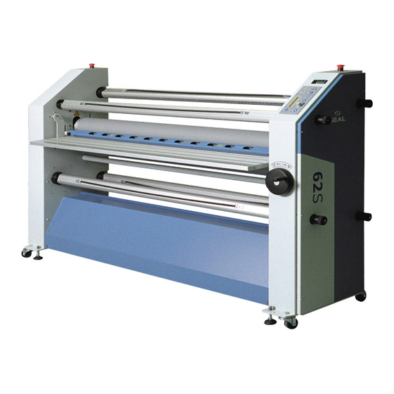
62C/62S
Mounter and Laminator
User Manual
UM114EN, Rev.2.0
Apr.2004
Table of
Contents
Previous
Page
Next
Page
1
2
3
4
5
Advertisement
Table of Contents
Need help?
Do you have a question about the 62C and is the answer not in the manual?
Ask a question
Questions and answers
Related Manuals for SEAL 62C
Laminator SEAL 62S User Manual
Mounter and laminator (44 pages)
Laminator SEAL Image 600-C Owner's Operation Manual
(32 pages)
Laminator SEAL 65ProMD User Manual
High production laminator, encapsulator, and mounter (63 pages)
Laminator SEAL 62 Ultra Owner's Operation Manual
(31 pages)
Laminator SEAL 54 EL User Manual
(144 pages)
Laminator SEAL 54 EL-1 Instruction Manual
Wide format cold roll laminator (151 pages)
Laminator SEAL SEAL 44/62 User Manual
Seal laminator user manual (35 pages)
Laminator SEAL 44/62 Ultra Plus User Manual
(33 pages)
Laminator SEAL 62Base User Manual
Mounter and laminator (36 pages)
Laminator SEAL 62Pro User Manual
Mounter, laminator and encapsulator (228 pages)
Laminator SEAL 62 Pro S User Manual
Mounter and laminator (212 pages)
Laminator SEAL 62 Pro Instruction Manual
Mounter, laminator and encapsulator (45 pages)
Laminator SEAL ProSEAL 44 Owner's Operation Manual
(18 pages)
Laminator SEAL 54Base User Manual
(32 pages)
Laminator SEAL 44 Ultra Laminator Owner's Operation Manual
44 ultra laminator (32 pages)
Laminator SEAL Image 6500 Owner's Manual
(38 pages)
This manual is also suitable for:
62s
Table of Contents
Print
Rename the bookmark
Delete bookmark?
Delete from my manuals?
Login
Sign In
OR
Sign in with Facebook
Sign in with Google
Upload manual
Upload from disk
Upload from URL


Need help?
Do you have a question about the 62C and is the answer not in the manual?
Questions and answers