Table of Contents
Advertisement
Advertisement
Table of Contents

Related Manuals for SEAL 44/62 Ultra Plus


Summary of Contents for SEAL 44/62 Ultra Plus
- Page 1 44/62 Ultra Plus Laminator User manual 7001507, Rev. 4 July 2007...
-
Page 2: Introduction
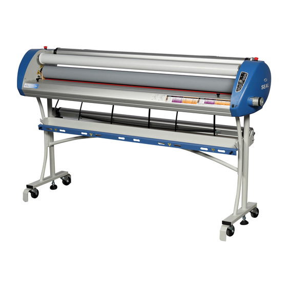
INTRODUCTION We would like to thank you for purchasing a Seal 44/62 Ultra Plus, designed to give you many years of reliable service. By following the guidelines outlined in this manual for proper care and use, you can depend on many years of trouble-free profitability from your investment. -
Page 3: Table Of Contents
TABLE OF CONTENTS Introduction Table of Contents Specifications Technical Specifications Electrical specifications 1.2.1 US versions 1.2.2 EU versions Safety / Important Safeguards Safety symbols used on the equipment. Emergency stop-buttons Unpacking and Installation Ambient Conditions Surroundings Power supply Workspace Requirements Setting up the laminator in 4 steps. - Page 4 Application Processes Loading the machine 6.1.1 Loading film onto a machine equipped with the interlock bracket. 6.1.2 Loading film onto a machine equipped with the cam lock system. 6.1.3 Loading the unwind shaft into a machine equipped with the interlock bracket. 6.1.4 Loading the unwind shaft into a machine equipped with the cam lock system.
-
Page 5: Specifications
1 SPECIFICATIONS 1.1 Technical Specifications Imperial Metric Max. Working Width processes up to 50° C 44 Ultra 44” maximum 1118 mm max. 62 Ultra 62” maximum 1574 mm max. processes up to 125° C 44 Ultra 42” maximum 1067 mm max. 62 Ultra 60”... -
Page 6: Electrical Specifications
1.2 Electrical specifications Push the power button (at least 1 sec.) and the forward (or reverse) button on the control panel, to run the laminator. The electrical specifications of the machines are: 1.2.1 US versions 44 Ultra Plus 1N/PE 115VAC +/-10%, 50/60Hz, 16A 62 Ultra Plus 1N/PE 230VAC +/-10%, 50/60Hz, 13A 62 Ultra S Plus... -
Page 7: Safety / Important Safeguards
2 SAFETY / IMPORTANT SAFEGUARDS 2.1 Safety symbols used on the equipment. ROTATING PARTS MECHANICAL HAZARD. FAILURE TO USE CAUTION NEAR EXPOSED ROLLERS COULD RESULT IN PHYSICAL INJURY. BE CAREFUL THAT ITEMS SUCH AS LOOSE CLOTHING, LONG HAIR AND JEWELRY DO NOT BECOME ENTANGLED IN ROTATING PARTS. -
Page 8: Unpacking And Installation
The following environmental conditions are ideal for the best operation of the laminator. Ambient Temperature The best temperature for the 44/62 Ultra Plus is between 16 C and 35 C (50 F and 95 F). Do not expose the laminator to direct sunlight as output quality may be affected. -
Page 9: Setting Up The Laminator In 4 Steps
3.5 Setting up the laminator in 4 steps. 1. Remove the cardboard box and the plastic bag as described on the outside of the box. 2. Pick the box behind the laminator which contains the stand parts. 3. Mount the LH-side part of the stand as shown in next figure. (The LH-part is recognizable by a spring utility on the bracket.) Use two serrated washers and two socket screws M6x16 (see fig.2) Do not tighten the screws completely. - Page 10 5. Finally, mount the middle part between the LH- and RH parts. Use two serrated washers and two socket screws M6x16. Do not tighten these screws completely Figure 4 6. Taking care to align the top of the LH stand so that it is parallel with the blue plastic cover and there is a small gap (1-2 mm) between the blue cover and the stand, tighten the 2 screws that hold the stand to the machine.
-
Page 11: Adjustable Feet
Your 44/62 Ultra Plus must be setup at the place where it will be used. The stand must be placed on a flat level surface. 12. Cut the tie-wraps and remove the blocks that hold the top roller. 13. Inspect the machine for any physical damage. -
Page 12: Unit Description
4 UNIT DESCRIPTION Features and benefits of the 44/62 Ultra Plus: Figure 7 Identification of parts Wind-up tube Wind-up for the release-liner Emergency stop button Image guide To help infeed images. It is removable when mounting. Upper unwind shaft The shaft is suitable for rolls having a 3-inch core Unwind brake A simple means of setting the unwind tension. -
Page 13: Control Panel
4.1 Control panel Drive symbol area LED run forward Lit when machine runs forward Button run Push button forward LED optical Lit when light beam is not safety system blocked. Stop button Push button LED run reverse Lit when machine runs reverse Button run Push button... -
Page 14: Slow-Mode
4.2.1 Slow-mode The machine has a slow-mode, which can be activated by pressing the foot switch. To maintain slow-mode, keep the foot switch pressed. WARNING: ONCE THE MACHINE IS RUNNING IN SLOW-MODE, INTERRUPTING THE PHOTOELECTRIC EYES DOES NOT STOP THE MACHINE; AN AUDIBLE BEEP WILL BE HEARD, AND THE ROLLER SPEED WILL BE DECREASED. -
Page 15: Unwind Brakes
4.3 Unwind brakes Tighten the supply brake so that it applies sufficient tension to laminate. Turning the knurled collar in a clockwise direction increases the breaking tension applied on the laminate. Turning the collar counter-clockwise decreases the tension. The best setting for the brake tension is determinate by the materials you are using and is learned through experience. -
Page 16: Process Control Sheet
5 PROCESS CONTROL SHEET Pressure Sensitive Thermal Application Recommended SEAL Unwind products Speed Unwind Recommended SEAL products Speed Temp 2 - 4ft/min 2 - 4ft/min Print Shield Print Guard UV/Jetguard 195 F / 90 C Rigid Display (0.6 - (0.6 -... -
Page 17: Application Processes
6 APPLICATION PROCESSES 6.1 Loading the machine The following steps outline the basic procedure that have to be used for loading materials, webbing the laminator and setting the brake tension for the materials you will be using. To load and unload the material shafts, it is necessary to access the machine from the rear side. -
Page 18: Loading Film Onto A Machine Equipped With The Cam Lock System
Figure 12 6.1.2 Loading film onto a machine equipped with the cam lock system. Remove the desired supply shaft (top or bottom) by moving the cam handle (1) down to the open position. Lift the autogrip shaft out of the laminator. Slide the shaft into a material roll. -
Page 19: Webbing The Films
6.2 Webbing the films After the laminator has heated up; Remove the infeed table. If applicable, the infeed table can be stored temporarily on the stand. Unroll the film on the top supply shaft, so that an adequate length is hanging over the top roller (see figures 13 &... - Page 20 Figure 17 Alternative way for webbing film on the bottom unwind. Use the provided leaderboard to push the film(s) through the nip (figure 18 or 19). Figure 18 Figure 19 Refer to the following sections for specific webbing diagrams based on the process you are performing.
-
Page 21: Feeding Images
6.3 Feeding images To aid feeding images, the laminator is provided with an “Image Guide”. This device can be positioned in front of the top roller and it prevents the images from interrupting the photoelectric eyes. When changing the roller nip, the Image Guide moves together with the top roller. -
Page 22: Laminating And Adhesive Coating (Decaling)
6.4 Laminating and adhesive coating (Decaling) This process involves sandwiching an image between either a hot or cold laminate on the face of the image and a pressure-sensitive adhesive on the rear. This process can be used to create self-adhesive images for mounting down onto various substrates. Once the machine reaches the operating temperature, the top roller may be raised and webbed as per the following diagrams. -
Page 23: Decaling Without Liner
6.5 Decaling without liner Preparation: Select the films that you will use on the top and bottom of the images, it is advisable to use slightly wider width films compared to the print width. This way the print can be trimmed with a border, so as to reduce waste, but be enough to leave a border. -
Page 24: Mounting
6.6 Mounting This process involves mounting down previously prepared decals onto a substrate. No films or adhesives are used in this process. To perform this process, it is necessary to remove the Image Guide, you can store the Image Guide in the machine stand (See fig. 9) 6.6.1 To mount decals onto a substrate Place the mounting board on a flat surface. -
Page 25: Encapsulating
6.7 Encapsulating This process involves completely sealing an image between two heat-activated films. Once the machine reaches the operating temperature, the laminator may be stopped, the top roller raised and webbed as per the following photographs and diagrams, refer to the Temperature/Speed chart on page 16 for settings and recommended film combinations. -
Page 26: Pre-Coating
6.8 Pre-Coating This process is used to coat substrates with a self-adhesive coating onto which images can be mounted. The same process is used to create a carrier board (sled). Preparation: Mount the roll of self-wound pressure sensitive adhesive onto the top unwind of the laminator with the exposed adhesive facing you. -
Page 27: Mounting And Lamination Using A Proseal Pouch Board
2. Also, refer to the instruction sheet for information on Compatible Media, Process Conditions and Technical Information. 3. A ProSEAL Pouch Board consists of a SEAL foam board mounting board with a piece of film on top. The film is sealed to the board along one of the short sides. Carefully examine the board to deter-mine which edge is sealed. -
Page 28: Encapsulating With A Proseal Flexible Pouch Using A Proseal Carrier Board
Separate the two pieces starting at the end opposite the hinge. Take care not to break the hinged seal. 4. Insert the article to be laminated in the pouch so there is at least a 1/8" (3.5mm) border around each of the sides. -
Page 29: Maintenance & Cleaning
7 MAINTENANCE & CLEANING Cleaning of the Machine The equipment must be disconnected from the mains before cleaning. The laminator may be cleaned by the operator with a lint-free cloth, lightly dampen with a mild soap and water solution. Spray-on cleaners are not to be used. No part of the machine is to be immersed in water or other liquids. -
Page 30: Troubleshooting
8 TROUBLESHOOTING List of common problems and solutions that the user can correct: Problem cause solution The power LED does not there is no power check if the power cable is come on, when the machine plugged into the mains wall is switched on. -
Page 31: Glossary Of Terms
9 GLOSSARY OF TERMS Decal An image that has been laminated on top (either heat-activated or pressure-sensitive) with an adhesive backing. Heat-Activated Laminates Laminates with a dry adhesive that is activated when heat is applied. Once applied to an image the adhesive forms a strong bond adhering the laminate and the image together. -
Page 32: Limited Warranty
10 LIMITED WARRANTY SEAL Graphics warrant to the original consumer purchaser that all new Seal® laminators that prove defective in materials or workmanship within the applicable warranty period will be repaired or, at our option, replaced without charge. The applicable warranty shall be one year from date of purchase with the exception of silicone roll coverings that will be six months from date of purchase. -
Page 33: Index
11 INDEX Application Processes .....17 Liability Statement ......2 Board Thickness ........5 Maintenance ........29 Max. Speed........5 Max. Working Width ......5 Cleaning...........29 Nip .............5 Dimensions ........5 Roller Pressure ........5 Environment Conditions.....8 Speed ..........5 Standardized Symbols .......2 Glossary of Terms......30 Technical Specifications.....5 Image Guide ........16 Interlock backet........19 Weight ..........5 Workspace Requirements ....8...
Need help?
Do you have a question about the 44/62 Ultra Plus and is the answer not in the manual?
Questions and answers