
Related Manuals for SEAL 65ProMD


Summary of Contents for SEAL 65ProMD
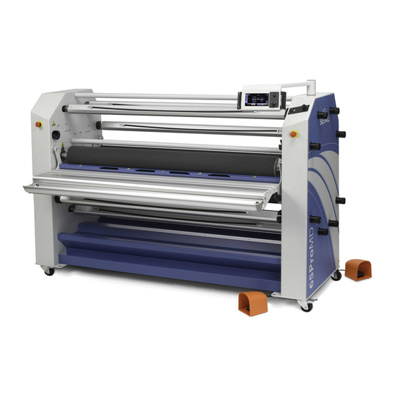
- Page 1 65ProMD High Production Laminator, Encapsulator, and Mounter User Manual 7003338, May 2013...
- Page 2 SEAL Graphics assumes no responsibility for any errors that may appear in this document nor does it make expressed or implied warranty of any kind with regard to this material, including, but not limited to, the implied warranties of merchantability and fitness for a particular purpose.
- Page 3 Introduction...
- Page 4 • Decaling • Encapsulating images Numerous laminating products are available under the SEAL brand, each with their own application and processing specifications. This manual gives a general description of the various processes. Additional details on film choice and application solutions can be found in the Neschen Americas Price Book or at www.sealgraphics.com.
- Page 5 THIS MANUAL This manual is intended for the user of the SEAL 65 Pro MD. Read this manual carefully before starting the machine. This manual contains important information for correct installation, operation and maintenance of the machine. It also contains important instructions to prevent accidents, personal injury and/or serious damage prior to or during operation of the machine.
-
Page 6: Table Of Contents
TABLE OF CONTENTS Warranty and Safety instructions 1.1 Warranty 1.1.1 Warranty conditions 1.1.2 Warranty period 1.2 Safety 1.2.1 Safety features 1.2.2 Safety instructions 1.3 Warnings 1.3.1 General ESD-warning 1.3.2 In this manual 1.3.3 On the machine Specifications 2.1 Identification 2.2 Machine specifications Installation 3.1 Unpacking 3.2 Installation... -
Page 7: Table Of Contentswarranty And Safety Instructions
5.3 Loading film rolls 5.3.1 Auto-grip shafts 5.3.2 Use of films with release liner 5.3.3 Loading shaft with film rolls 5.3.4 Presetting the tension 5.3.5 Pressure setting 5.4 Webbing 5.4.1 Upper section only 5.4.2 Upper and lower section 5.4.3 Webbing both upper and lower films. 5.4.4 Roll to roll 5.4.5 Pull rollers 5.5 Processes and settings... -
Page 9: Warranty And Safety Instructions
1.1 Warranty The warranty period and conditions stated in this chapter are merely a summary of the general SEAL brand laminator warranty conditions. For the exact details on the warranty period and conditions for your machine, please contact Neschen Americas Technical Support or your reseller. -
Page 10: Safety
1.2 SAFETY This machine is provided with safety equipment to promote safe machine operation. The manufacturer has done everything possible to prevent any possible danger and to inform you as accurately and comprehensively as possible of any hazards relating to the operation of the machine. -
Page 11: Safety Instructions
1.2.2 Safety instructions Work safely! The owner of the machine is responsible for safe operation of the machine. He therefore is obliged to familiarize operating personnel with the contents of this manual and make them aware of all possible hazards. Do not change, remove or disable the safety facilities. -
Page 12: On The Machine
1.3.3 On the machine On the machine you will find the following warning symbols in black on a yellow background. HOT OBJECTS DANGER OF GETTING BURN WOUNDS. MAKE SURE NOT TO TOUCH THE MAIN ROLLERS WHEN HEATED. This symbol is placed on the inside side panel on both sides of the machine, just above the upper main roller, visible from the front and rear side, and on the image guide at the input side of the nip. -
Page 13: Specifications
2. SPECIFICATIONS 2.1 Identification The machine identification label is located at the bottom of the right-hand cabinet, on the rear side of the machine. This label indicates the model (version) and the power supply requirements. CAUTION: The mains supply must match the values indicated on the machine identification label. -
Page 14: Machine Specifications
Slitters Noise Level <70 dB(A) Mechanical Requirements 2 cfm compressed air @ 100 psi SEAL 65 Pro MD Part Number 64600 Warranty 1 year parts / 6 months labor Extended Warranty Options available to cover your machine for 3 years total (includes Standard Warranty). -
Page 15: Installation
3. INSTALLATION WARNING: INSTALLATION MUST BE CARRIED OUT BY SKILLED PERSONNEL. Note: Make sure that the machine, in its final location, has adequate space. You will need room to feed, receive and trim images. Only skilled personnel should perform installation. Read and comply with all warnings and follow the proper installation procedures and safety guidelines. - Page 16 Place the pallet in a space where there is enough room to roll the machine off from the pallet (approx. 3x the length). To unpack, follow the steps below: a. Cut the straps and lift off the carton box. b. Remove the plastic bag. Figure 2: Removing transport parts.
- Page 17 Figure 3: Ramp positioning. h. Place the two ramps (3) against the end of the pallet so that the castors (4) will roll down the ramps without falling off. Scew the ramps to the pallet to keep them from moving when unloading the machine. Unlock the casters.
-
Page 18: Installation
3.2 Installation a. Move the machine (and the accessories) to its final location. Note: Allow ample working space. See figure 4. Figure 4: Working space. Working space Width Depth 2x maximum board length + Note: Anti-static clothing and footwear of the operator and an anti-static floor coating will help reduce the build up of electrostatic (dis)charges (ESD). -
Page 19: Transport
CAUTION: Check the mains values before connecting. See section 2.1 for power supply details d. Connect the machine to the mains using the power cable supplied with the machine. CAUTION: Only if absolutely necessary, use an extension cable of ample capacity. Unroll the extension cable completely. -
Page 20: Description
4. DESCRIPTION This chapter describes the machine and its operating basics. 4.1 General description The machine described in this manual is a multi-directional machine dedicated for processing pressure sensitive or heat activated laminating materials. While feeding through images and coating films, the two silicone coated main rollers generate the nip pressure. -
Page 21: Parts Identification
4.2 Parts identification Figure 5: Parts Idenification. 1. Main roll (top front) 2. Pull roll (top rear) 3. Swing out supply shaft (top rear) 4. Swing out supply shaft (top front) 5. Swing out supply shaft (bottom Front) 6. Take up autogrip shaft (bottom front) 7. -
Page 22: Process Principle
4.3 Process principle In all processes the materials are fed through the nip from the infeed side to be joined together by pressure and/or temperature. A process that makes maximum use of the machine is shown in figure 6. Figure 6 Shown is an image roll to roll process with a heat activated top and bottom layer. - Page 23 The optional slitters (11) can be used to cut off the edges when processing roll to roll. Figure 7: Creating Pop-up art, including image supply roll trough. Description...
-
Page 24: Machine Operation
5.1 Machine controls 5.1.1 Easy Operator Interface (EOI) In order to take full advantage of your new SEAL 65 Pro MD, it is important to become familiar with the new Easy Operator Interface The Easy Operator Interface is the first windows-based control panel for a laminator. As such, it can be updated and enhanced with future improvements. -
Page 25: Home Screen
5.1.1.1 The Home Screen Here is a summary of the Home Screen buttons. These buttons are always visible no matter what screen is active inside the grey box. On the home screen the machine status of all functions are displayed inside the black box outlined in grey. 1. - Page 26 Here is a summary of the Home Screen status display. As you can see, this is the location where all current settings are reflected. You can always get to this screen by clicking the SEAL “S”. 7003338 - User Manual 65 Pro MD...
- Page 27 1. Front nip pressure display a. Display a percent of nip pressure (1-100). Updates real time. 2. Front nip opening display a. Display only: show the current nip setting. b. Numbers red when rolls are not at current nip setting. c.
-
Page 28: Heater Screen
5.1.1.2 The Heater Screen Both the top and bottom rollers can be heated. You can set the heat by typing in the temperature. When typing you will see the numbers turn from red to white indicating a valid temperature. Use the “X” to backspace and the green check to apply the temperature. - Page 29 1. Heater on / off button a. This is a toggle button to turn the heater on or off, the window in the button turns red when the heater is on. 2. Number entry pad a. Actions: Pressing any number first clears the current value in the temperature set point display and then displays the numbers pushed in order from left to right.
- Page 30 Setting the roll temperature Be sure to turn the heater on or off using the icon near the slider bar. 7003338 - User Manual 65 Pro MD...
- Page 31 Machine Operation...
-
Page 32: Help Screen
The numbers in the front rollers indicate the roller temperature. They will be RED until they reach the desired temperature and then turn green. 5.1.1.3 The Help Screen You can click the Question mark to open the help file. Currently, this allows you to change from Fahrenheit to Celsius, but will include more help as new generations of the EOI are updated. - Page 33 Machine Operation...
-
Page 34: Nip Screen
5.1.1.4 The Nip Screen The rolls on the 65Pro MD are pneumatically raised and lowered. The position that the rolls move to when they are lowered is controlled by electronically moving a stop that holds the rolls open to any position that the user enters. In order to change the nip setting, the rolls must be in the raised position. - Page 35 1. Number entry pad a. Actions: Pressing any number first clears the current value in the nip height display and then displays the numbers pushed in order from left to right. b. The – and / symbols are used for fractional number entry in the form of “1-3/8” to represent 1.375”.
- Page 36 Setting the Nip Height 7003338 - User Manual 65 Pro MD...
- Page 37 After the check mark is selected you will return to the home screen. The numbers indicating the nip height set point will be updated with the new set point value. They will be RED until the nip reaches the desired position. Then the numbers will turn green. The nip will not go to a new position if the rolls are down.
-
Page 38: Additional Controls
5.1.2 Additional controls Figure 8: Front controls Emergency stop buttons (1): There are 4 emergency stops on the machine. Two are located on the front of the machine (see section 4.2), and two are in the same locations on the back of the machine. The emergency switches are push button switches. - Page 39 Figure 10: Rear Controls Emergency stop buttons (1): There are 4 emergency stops on the machine. Two are located on the front of the machine (see section 4.2), and two are in the same locations on the back of the machine. The emergency switches are push button switches.
- Page 40 Air water trap (7) The air water trap removes water from the incoming air. Twist the valve on the bottom of the trap to drain the water from the trap. The water should be drained at least once a week. Humid conditions may cause a need to drain the trap more often. Figure 11: Shaft brakes, clutches, and combi controls Unwind tension control (1) knob:...
- Page 41 Figure 13: Pendant Controls Speed potentiometer (1): The speed potentiometer increases the speed of the machine as it is turned clockwise. The speed is reduced by turning the knob counter-clockwise. The current speed setting is displayed on the EOI. Stand by switch (2): The machine can be placed into the standby mode by toggling the standby switch.
-
Page 42: Operating Modes
5.2 Operating modes The 65 Pro MD has two speed modes. The machine is either in normal speed mode or slow speed mode. In both normal and slow mode the rollers can rotate in forward or in reverse direction. The rotation speed of the rollers in normal mode is set via the speed control knob. -
Page 43: Slow Mode
5.2.3 Slow mode Slow mode is activated when the laminator is running and the photo eyes at the in feed side of either nip are blocked. This is indicated by the snail icon on the EOI screen. Entering slow mode will force the machine to run at 2 ft per minute unless the potentiometer is turn all the way to zero (counter-clockwise). -
Page 44: Loading Film Rolls
5.3 Loading film rolls 5.3.1 Auto-grip shafts All auto-grip shafts operate in the same fashion. Their function is determined by their position in the machine. The drop in shafts fit into the machine in either direction. On the control panel side of the machine the auto-grip shaft gripper snaps into the brake or clutch gripper slot in the shaft holder. -
Page 45: Loading Shaft With Film Rolls
5.3.3 Loading shaft with film rolls The way the roll of film is put on the shaft depends on the type of film used and whether you are placing it in the upper or lower section of the machine. In general, film with release liner is rolled up with the liner (and adhesive) to the outside, whereas film without release liner has its adhesive layer to the inside of the roll. -
Page 46: Presetting The Tension
5.3.4 Presetting the tension To enable the film to unwind without wrinkles, a brake tension can be set to the roll. On the right-hand side of the machine you will find tension control knobs, corresponding with each shaft. Turn the tension control knob clockwise to set the tension or counter clockwise to release the tension. -
Page 47: Webbing
5.4 Webbing For most processes the machine must be webbed before images on thin film or on panels can be processed. The machine can be webbed for single sided or double sided processing. Note: In single sided processes, adhesive residues will stay behind on the bottom roller where the film is wider than the images. -
Page 48: Webbing Both Upper And Lower Films
5.4.3 Webbing both upper and lower films. The film in the upper section is webbed first a. Remove the image guide. b. Feed the film underneath the splitter bar (between splitter bar and upper roller). Pressure sensitive film (without a release liner) from the top unwind shaft must be •... -
Page 49: Roll To Roll
5.4.4 Roll to roll When webbing for the roll to roll process, the lower front unwind/wind-up shaft is used as a supply (unwind) shaft for the images. Single sided lamination; When laminating single sided the unwind/windup shaft in the rear of the lower section can be used to wind-up the completed product. -
Page 50: Pull Rollers
5.4.5 Pull rollers The pull rollers are generally used in the encapsulation process (hot processing double sided lamination) to get a better encapsulation result. Before webbing set the top pull roller in the upper position and lock it on both sides. •... -
Page 51: Pre-Coating Panels
d. Put the image on top of the board (image side up). Turn back the image at the machine side (1). e. Turn back approx. 25 mm (10 in.) release liner (2) at the machine side and crease this evenly from the inside out. Note: The final quality depends on the way in which the leading edge of the image is applied to the board. -
Page 52: Single-Sided Lamination
d. Set the pressure while feeding the leader board. e. Before the end of the leader board enters the nip, butt up the panel to be pre-coated. When more panels have to be pre-coated feed them in continuously without any gap. At the end, use a leader board again to finish. -
Page 53: Over-Lamination
Switch ON both heaters, set the temperatures (see the specifications of the • materials used) and allow ample time to reach the set temperature. Set the upper pull roller in the upper position before webbing and lock it in position. •... - Page 54 Process Control Sheet Note: We recommend that you make a photocopy of this page. With each successfully run application, record the process and settings and a diagram of the webbing procedure. Keep the record so the application can be repeated at a later date. Hint: If a standard image is made available for each new process then sales materials and samples can be developed for reference.
- Page 55 Figure 1: Blank Webbing Diagram Machine Operation...
-
Page 56: Maintenance
6. MAINTENANCE 6.1 Cleaning The machine has to be cleaned regularly. Dirt and dust will have a negative influence on the result of the lamination processes. CAUTION: Do not use abrasive materials for cleaning the machine. This can damage the painted surfaces or the silicone covering of the rollers. Use a damp cloth for cleaning. -
Page 57: Preventive Maintenance
6.2 Preventative maintenance Our machines are designed in such way that they need little (preventative) maintenance in addition to the cleaning. The following checks have to be performed: • Auto-grip shafts with blocking cords. 6.2.1 Auto-grip shafts Check the auto-grip mechanism on each shaft. •... -
Page 58: Pressure Too Low
6.3.2 Pressure too low. Figure 4: Wrinkles due to low pressure. • Increase the roller pressure a little (5-10%). 6.3.3 Unwind tension too low. Figure 5: Wrinkles due to low unwind tension. • Increase the unwind tension until the wrinkles (6) in the film on the roller disappear. The lines (7) in the process result will disappear as well. -
Page 59: Too Much Heat In The Final Result
6.3.5 Too much heat in the final result. Figure 7: Wrinkles due to too much heat. The result is still too hot after the pull rollers. The bottom pull roller also gets hot. • Reduce the heater settings. • Check the function of the cooling device or have the device installed. 6.3.6 Roller alignment fault. -
Page 60: Machine Operation Issues
6.3.8 Machine operation issues Problem Solution The laminator will not turn on. Check if the power cable is plugged into the wall outlet. • Check that the Stand-by switch is ON. • Make sure the main circuit breakers and machine circuit breakers are •... -
Page 61: Technical Assistance
6.3.10 Technical assistance For Technical assistance contact Neschen Americas Technical Support at 1-800-486- 6502. Make a clear description of the problem before contacting Technical assistance. Please have the Model number and the Serial Number of your machine at hand. You can find this data on the identification plate of your machine, which can be found on the rear side of the right cabinet. -
Page 62: Glossary
7. GLOSSARY Carrier board or sled A board with a non-stick surface that is used when laminating one side of an image only. Decal An image with an adhesive backside (ex. sticker). Decaling Providing an image with laminate on the image side and adhesive on the backside. Encapsulating Sandwiching an image between two heat sensitive films . - Page 63 Contact Us: Seal Brands Technical Service – US & Canada SEAL Brands Technical Service – Europe & Asia Pacific 1-800-486-7325 +49 5722 207 354 Fax: 1-800-966-4554 Fax: +49 5722 207 255 Email: service@neschenamericas.com Email: technical@neschen.de parts@neschenamericas.com SEAL Brands Customer Service – US & Canada...
Need help?
Do you have a question about the 65ProMD and is the answer not in the manual?
Questions and answers
troubleshoot the heat will not come on