
Related Manuals for SEAL Image 6500


Summary of Contents for SEAL Image 6500
- Page 1 Image 6500 Laminator ® Owners Manual - English Manual del Usuario • Manuale Utente Gebrauchsanleitung • Manuel d’ Utilisation • Image 6500 Laminator ® Kaschiermaschine • Machine laminer • Lamina Dora • Laminatore...
-
Page 2: Table Of Contents
S E A L I M A G E 6 5 0 0 L A M I N A T O R — T A B L E O F C O N T E N T S ® ® Introduction . -
Page 3: Introduction
STATEMENT OF INTENDED USE ® ® We have designed the SEAL Image 6500 to give you years of Your SEAL Image 6500 Laminator meets the CE reliable service. As you become familiar with your laminator, Machinery Safety Directive (89/392/EEC, including... -
Page 4: Electrical Specifications
Power Cord Strain Relief: Turn clockwise to tighten. Grounding Lug IMPORTANT! SEAL Graphics recommends that a licensed electrician, in accordance with electrical codes **IMPORTANT: The ground (green wire) should be two inches longer than the black and white wires in your area, install your mains power. -
Page 5: Workspace Requirements
W O R K S P A C E R E Q U I R E M E N T S • Keep the area around your laminator clear with adequate space around it so you can feed, receive and trim mounted and/or laminated images. -
Page 6: Environment Conditions
AMBIENT TEMPERATURE output. The best temperature for the SEAL Image 6500 is The background dust level must not exceed that found in between 50°F and 86°F (10°C and 30°C). a typical office/computer room environment. -
Page 7: Unpacking, Set-Up And Installation
U N P A C K I N G , S E T- U P A N D I N S T A L L A T I O N Only skilled personnel should perform installation. Read and comply with all warnings and follow the proper installation procedures and safety guidelines. - Page 8 U N P A C K I N G , S E T- U P A N D I N S T A L L A T I O N UNPACKING YOUR LAMINATOR WARNING! Do not use open blades to remove the protective paper on the rollers.
-
Page 9: Important Safeguards
The service technician must use replacement parts specified by of the risk of being injured by voltage. SEAL Graphics. Only authorized maintenance and ser- vice technicians or safety personnel Service Technicians must perform safety checks after should have access to the keys for completing any service or repairs to the laminator. -
Page 10: Safety Features
S A F E T Y F E A T U R E S The SEAL Image 6500 Laminator is designed Photoelectric Safety Eyes: with safety and protective devices with the user’s A light beam path set directly in front and back of the safety of utmost consideration. -
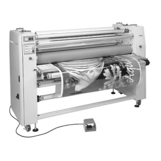
Page 11: Laminator Features
L A M I N A T O R F E A T U R E S Figure 4. Laminator Features Features 1. Control panel system 9. Autogrip Roll Easel Shaft • Removable media unwind shaft for images on a roll. Allows for roll- •... - Page 12 F R O N T C O N T R O L P A N E L 1. Air Pressure Gauge: Indicates the PSI reading for the 11. Bottom Roller Temperature Increase Button: Press downward pressure of the top main roller. The standard this button once to view the temperature set point.
- Page 13 B A C K C O N T R O L P A N E L 1. Air Pressure Gauge: Indicates the PSI reading for the downward pressure of the top pull roller. The standard setting for the normal operation is 35-55 PSI. 2.
- Page 14 C L U T C H C O N T R O L P A N E L The Clutch Control Panel is located on the left-side 1. AIR PRESSURE GAUGE cabinet when facing the rear of the laminator. The Indicates the PSI reading for the pulling tension of the operator can adjust the amount of tension that is bottom pull roller.
- Page 15 T O P M O T O R C O N T R O L P A N E L S The Motor Control Panels are centrally located on 2. Reverse Roller Direction Switch the top of both side cabinets. This location provides Pressing this switch runs the rollers in the reverse direction easy access from all sides of the laminator.
-
Page 16: Checking Operation
C H E C K I N G O P E R A T I O N After you are familiar with the control panels and • Press the green Motor Reverse switch and the rollers their functions, check all operations. should rotate in the reverse direction. -
Page 17: Set-Up And Operation
• Check which temperature setting is recommended for • You must first raise the rollers and then turn the shim your SEAL Brands material (see literature enclosed in wheels until the desired measurement corresponds with ®... - Page 18 S E T- U P A N D O P E R A T I O N LOADING A ROLL OF MATERIAL • Turn the unwind brake fully towards you so there is no brake tension on the unwind shaft (until no gap is visible between the unwind brake and the lock collar).
- Page 19 S E T- U P A N D O P E R A T I O N PIVOTING TABLE USE FOR WEBBING • Pull the film up and place it over the top roller. • First, remove the roll easel shaft from its brackets and •...
- Page 20 • Reverse the above procedures to change from the top COOLING SYSTEM location to the bottom location. • The SEAL Image 6500 has a dual-position cooling tube, • The cooling tube can also be rotated to direct the airflow which can be placed above or below the center chill as needed.
- Page 21 S E T- U P A N D O P E R A T I O N AUTO-RUN OPERATION WARNING! While using the foot switch, interrupting the photoelectric safety eyes does NOT stop the lamina- • The continuous-run operation allows the user to set the tor.
-
Page 22: Feeding Images
F E E D I N G I M A G E S BASIC STEPS TO FEEDING IMAGES USING THE ROLL EASEL ATTACHMENT The Roll Easel Attachment is used to encapsulate images NOTE: For good results, the process requires that the digitally reproduced with a color plotter. -
Page 23: Webbing Films Without A Release Liner
W E B B I N G F I L M S W I T H O U T A R E L E A S E L I N E R The following are the basic webbing procedures for •... -
Page 24: Webbing Films With A Release Liner
W E B B I N G F I L M S W I T H A R E L E A S E L I N E R The following are the basic webbing procedures for • Raise the top pull roller and advance the leader-board webbing films with a release liner: through the pull rollers. -
Page 25: Decaling (Heat-Activated)
D E C A L I N G ( H E A T- A C T I V A T E D ) This process involves applying a hot film to the top Note: When using Mounting Adhesive on the back of and a cold backing adhesive to the bottom of the images it is best to run over both idlers. -
Page 26: Decaling (Pressure-Sensitive)
D E C A L I N G ( P R E S S U R E - S E N S I T I V E ) This process involves applying a cold pressure-sensi- NOTE: Pressure-sensitive films, not requiring heat, can tive over-laminate to the top and a cold pressure- be run from the front or rear of the laminator sensitive mounting adhesive to the bottom of a... -
Page 27: Mounting
M O U N T I N G This process involves mounting previously prepared • At this point, continuous run can be selected by pressing decals onto a substrate. No films or adhesives are the Forward Motor Direction switch. required for this process. NOTE: Take care that the rollers do not grab the liner. -
Page 28: Encapsulating
E N C A P S U L A T I N G This process involves completely sealing an image between two films. Follow the webbing instructions for films specific for your location. MEDIA: Ink Jet, Electrostatic, and Photographic FILMS: -- -- -- Top Unwind Shaft: Heat-Activated Laminate 3–5 Mil (75-125 microns) Shim Wheel... -
Page 29: Pre-Coating Boards
P R E - C O A T I N G B O A R D S This process is used to coat substrates with a self- adhesive coating onto which images can be mounted. Preparation: IMPORTANT! Ensure that the Shim Wheel settings of the rollers correspond to the board thickness. -
Page 30: Low-Temp Vinyl Transfer
L O W - T E M P V I N Y L T R A N S F E R This process involves transferring an image onto a flexible vinyl. Top roller temperature and amount of main roller downward pressure is dependent on the type of toners. -
Page 31: Process Control Sheet
P R O C E S S C O N T R O L S H E E T Process: ______________________________________ NOTE: We recommend that you make a photocopy of this page. With each successfully run application, Application Use: _______________________________ record the process and settings and a diagram of the Top Unwind Shaft: ______________________________ webbing procedure. -
Page 32: Cleaning/Maintaining Your Laminator
• For adhesive that is difficult to remove, allow the rollers your warranty. to cool and use isopropyl alcohol (IPA) and a clean, lint- Call SEAL Graphics Technical Service for further free cloth. Never pour isopropyl alcohol (IPA) directly assistance (see rear cover). -
Page 33: Periodic Maintenance Sheet
** Use lightweight household oil to oil the chain approximately every three months. *** Drain the air filter approximately every six months to prevent moisture damage to the air cylinders. Call SEAL Graphics Technical Service for assistance (see the rear cover). -
Page 34: Trouble Shooting Guide
• Thicker films may require increased roller pressure due to the thicker film layer. Technical Service: For technical assistance, please contact your SEAL Graphics Technical Service representative (see rear cover). When calling for Technical Service please have the Laminator Serial Number (listed on the identification plate) available. -
Page 35: Glossary Of Terms
G L O S S A R Y O F T E R M S Decal: Nip: An image that has been laminated on top (either heat-activat- The spot where the top and bottom rollers meet. ed or pressure-sensitive) with an adhesive backing. Out-Feed: Film: The side of the laminator from which completed images... -
Page 36: Spare Parts List
S P A R E P A R T S L I S T PART DESCRIPTION PART # Air Compressor 225020 Fan Tube 615463 Roll Easel Shaft Assembly 5520 Supply Shaft Assembly 5519 Table, Image Guide (Front) 5521 Table, Print Guide (Rear) 5522 Take-Up Shaft Assembly 5518... -
Page 37: Technical Specifications
SEAL Image 6500 Three-phase 60425 Each SEAL Image Laminator has a Serial Number Label located on the right-side cabinet when facing the rear. This label indicates the model type, the electrical requirements, and the laminator serial number (important for reference if... -
Page 38: Limited Warranty
SEAL Graphics warrants to the original consumer purchaser NOTE: This equipment has been tested and found to comply that each new SEAL Brands Image Laminator, which proves with the limits for a Class A digital device, pursuant to Part defective in materials or workmanship within the applicable 15 of the FCC rules.
Need help?
Do you have a question about the Image 6500 and is the answer not in the manual?
Questions and answers